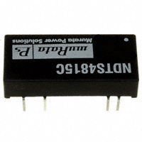
NDTS Series
Isolated 3W Single Output DC/DC Converters
SELECTION GUIDE
Input Voltage V (Nom.)
5 5 5 5 12 12 12 12 24 24 24 24 48 48 48 48
Order Code
NDTS0503C NDTS0505C NDTS0512C NDTS0515C NDTS1203C NDTS1205C NDTS1212C NDTS1215C NDTS2403C NDTS2405C NDTS2412C NDTS2415C NDTS4803C NDTS4805C NDTS4812C NDTS4815C
Output Current Rated Output Voltage Min. Load Full Load V mA mA
3.3 5 12 15 3.3 5 12 15 3.3 5 12 15 3.3 5 12 15 227 150 63 50 227 150 63 50 227 150 63 50 227 150 63 50 909 600 250 200 909 600 250 200 909 600 250 200 909 600 250 200
Input Efficiency Isolation MTTF2 Current (Min.) Capacitance mA % pF kHrs
898 806 769 757 350 320 310 310 172 156 149 147 87 83 76 75 63 71 76 77 71 73 75 76 71 78 80 84 71 75 80 80 28 30 32 33 29 32 35 32 32 32 35 35 32 32 40 40 1658 1665 1650 1633 1668 1665 1650 1633 1671 1673 1650 1617 1676 1668 1631 1600
FEATURES
RoHS compliant Industry standard footprint Single isolated output Short circuit protection Operating temperature range –40°C to +85°C Low profile 24 pin case 2:1 Wide input range
INPUT CHARACTERISTICS
Parameter
Voltage range
Conditions
All NDTS05 types All NDTS12 types All NDTS24 types All NDTS48 types All NDTS05 types All NDTS12 types All NDTS24 types All NDTS48 types
Min.
4.5 9 18 36
Typ.
5 12 24 48 50 30 40 30
Max.
9 18 36 72 150 100 50 40
Units
V
5V, 12V, 24V & 48V Input 3.3V, 5V, 12V & 15V Output Footprint 4.73cm2 UL94V-0 Package materials No heatsink required Internal SMD construction Fully encapsulated
Reflected ripple current1
mA p-p
OUTPUT CHARACTERISTICS
Parameter
Voltage set point accuracy Line regulation
Conditions
With external input/output capacitors Low line to high line with external input/ output capacitors 0503, 0505, 1203, 1205
Min.
Typ.
±1 0.15 0.8 0.8 0.1 15 90
Max.
±3 0.5 1.0 1.2 0.5 40 150
Units
% %
DESCRIPTION
The NDTS series is a range of low profile DC/DC converters offering a single regulated output over a 2:1 input voltage range. All parts deliver 3W output power up to 85°C without heatsinking. A flyback oscillator design with isolated feedback is used to give regulation over the full operating range of 25% to 100% of full load. It is strongly recommended that external capacitors be used on input and output to guarantee performance over full load and input voltage range (see recommended filter circuit for values).
Load regulation
Minimum load to rated load with external input/ output capacitors
2403, 2405, 4803, 4805 12V & 15V outputs
%
Ripple Ripple & noise
BW = 20Hz to 300kHz with external input/ output capacitors BW = DC to 20MHz with external input/output capacitors
mV rms mV p-p
1. Please refer to relected ripple current measurement circuit on page 2. 2. Calculated using MIL-HDBK-217F with nominal input voltage at full load (ground benign) at 25°C. 3. Please refer to minimum load application note on page 4. All specifications typical at TA=25°C, nominal input voltage and rated output current unless otherwise specified.
For full details go to www.murata-ps.com/rohs
www.murata-ps.com
Technical enquiries - email: mk@murata-ps.com, tel: +44 (0)1908 615232
KDC_NDTS_D02 Page 1 of 6
�NDTS Series
Isolated 3W Single Output DC/DC Converters
ABSOLUTE MAXIMUM RATINGS
Short-circuit protection Lead temperature 1.5mm from case for 10 seconds Minimum output load for specification3 Input voltage 05 types Input voltage 12 types Input voltage 24 types Input voltage 48 types Free air space 8 Hours 300°C 25% of rated output 10V 20V 40V 80V 10mm Min. around component
GENERAL CHARACTERISTICS Parameter
Switching frequency
Conditions
100% to 25% load, VIN Min. to Max.
Min.
70
Typ.
Max.
650
Units
kHz
ISOLATION CHARACTERISTICS
Parameter
Isolation voltage Resistance
Conditions
Flash tested for 1 second Resistance
Min.
1000 1
Typ.
Max.
Units
VDC GΩ
TEMPERATURE CHARACTERISTICS
Parameter
Operation Storage NDTS0515C, NDTS1205C, NDTS1212C, NDTS1215C, NDTS2405C, NDTS2412C, NDTS2415C, NDTS4812C & NDTS4815C NDTS0505C, NDTS0512C, NDTS1203C, NDTS2403C, NDTS4803C & NDTS4805C NDTS0503C
Conditions
Min.
-40 -50
Typ.
Max.
85 130
Units
30 40 50
Case temperature rise above ambient in still air
ºC
TECHNICAL NOTES
ISOLATION VOLTAGE
‘Hi Pot Test’, ‘Flash Tested’, ‘Withstand Voltage’, ‘Proof Voltage’, ‘Dielectric Withstand Voltage’ & ‘Isolation Test Voltage’ are all terms that relate to the same thing, a test voltage, applied for a specified time, across a component designed to provide electrical isolation, to verify the integrity of that isolation. Murata Power Solutions NDTS series of DC/DC converters are all 100% production tested at their stated isolation voltage. This is 1kVDC for 1 second. A question commonly asked is, “What is the continuous voltage that can be applied across the part in normal operation?” For a part holding no specific agency approvals, such as the NDTS series, both input and output should normally be maintained within SELV limits i.e. less than 42.4V peak, or 60VDC. The isolation test voltage represents a measure of immunity to transient voltages and the part should never be used as an element of a safety isolation system. The part could be expected to function correctly with several hundred volts offset applied continuously across the isolation barrier; but then the circuitry on both sides of the barrier must be regarded as operating at an unsafe voltage and further isolation/insulation systems must form a barrier between these circuits and any user-accessible circuitry according to safety standard requirements.
REPEATED HIGH-VOLTAGE ISOLATION TESTING
It is well known that repeated high-voltage isolation testing of a barrier component can actually degrade isolation capability, to a lesser or greater degree depending on materials, construction and environment. The NDTS series has an EI ferrite core, with no additional insulation between primary and secondary windings of enameled wire. While parts can be expected to withstand several times the stated test voltage, the isolation capability does depend on the wire insulation. Any material, including this enamel (typically polyurethane) is susceptible to eventual chemical degradation when subject to very high applied voltages thus implying that the number of tests should be strictly limited. We therefore strongly advise against repeated high voltage isolation testing, but if it is absolutely required, that the voltage be reduced by 20% from specified test voltage. This consideration equally applies to agency recognized parts rated for better than functional isolation where the wire enamel insulation is always supplemented by a further insulation system of physical spacing or barriers.
RoHS COMPLIANCE INFORMATION
This series is compatible with RoHS soldering systems with a peak wave solder temperature of 300ºC for 10 seconds. The pin termination finish on this product series is Tin. The series is backward compatible with Sn/Pb soldering systems. For further information, please visit www.murata-ps.com/rohs
www.murata-ps.com
Technical enquiries - email: mk@murata-ps.com, tel: +44 (0)1908 615232
KDC_NDTS_D02 Page 2 of 6
�NDTS Series
Isolated 3W Single Output DC/DC Converters
APPLICATION NOTES
Recommended Input & Output Capacitors
Although these converters will work without external capacitors, they are necessary in order to guarantee the full parametric performance over the full line and load range. All parts have been tested and characterized using the following values and test circuit. Input Voltage 5V, 12V 24V, 48V CIN 100μF, 25V (0.25Ω at 100kHz) 10μF, 100V (1.5Ω at 100kHz) Output Voltage 3.3V, 5V 12V, 15V COUT 220μF, 16V (0.12Ω at 100kHz) 100μF, 25V (0.25Ω at 100kHz)
Test circuit
+ VOUT Supply + VIN + VIN
CIN
Supply - VIN - VIN
NDTS
- VOUT
COUT
Reflected Ripple Current Measurement
12μH Supply + VIN Current Probe + VIN + VOUT
C1
CIN
NDTS
- VOUT
COUT
Load
Supply - VIN
C1 = 220μF, ESR < 0.1Ω at 100kHz
- VIN
www.murata-ps.com
Technical enquiries - email: mk@murata-ps.com, tel: +44 (0)1908 615232
KDC_NDTS_D02 Page 3 of 6
�NDTS Series
Isolated 3W Single Output DC/DC Converters
APPLICATION NOTES (continued)
Minimum Load
The minimum load for correct operation is 25% of the full rated load across the specified input voltage range. Lower loads may cause a significant increase in output ripple and may cause the output voltage to exceed its specification transiently during power-down when the input voltage also falls below its rated minimum. The following graphs show the typical required minimum load required for stable operation in mA verses input voltage. Some variants are not included as they do not typically require a minimum load for stable operation: NDTD1212C, and NDTD1215C. The NDTS series will operate from a wider input range than specified in the input characteristics datasheet table with output power derating. Please contact Murata Power Solutions for further information.
NDTD05XXC
200 180 160 Minimum Load (mA) 140 120 100 80 60 40 20 0 4.5 5.5 6.5 7.5 8.5 Input Voltage (V) 9.5 10.5 0515 11.5 0512 0503 0505
NDTD12XXC
Minimum Load (mA)
1203
1205
9
11
13
15 Input Voltage (V)
17
19
21
www.murata-ps.com
Technical enquiries - email: mk@murata-ps.com, tel: +44 (0)1908 615232
KDC_NDTS_D02 Page 4 of 6
�NDTS Series
Isolated 3W Single Output DC/DC Converters
APPLICATION NOTES (continued) NDTD24XXC
200 180 160 140 Minimum Load (mA) 120 100 80 60 40 20 0 10 15 20 25 30 35 40 2415 24 12 45 2405 2403
Input Voltage (V)
NDTD48XXC
120
100 0503 Minimum Load (mA) 80
60 0505 40 0512 0515 20
0 30
35
40
45
50
55
60
65
70
75
80
Input Voltage (V)
www.murata-ps.com
Technical enquiries - email: mk@murata-ps.com, tel: +44 (0)1908 615232
KDC_NDTS_D02 Page 5 of 6
�NDTS Series
Isolated 3W Single Output DC/DC Converters
PACKAGE SPECIFICATIONS
MECHANICAL DIMENSIONS
1.270 (32.26)
PIN CONNECTIONS Pin
0.200 (5.08)
Function
-VIN -VIN NA NC +VOUT -VOUT +VIN +VIN
NDTS2412C
XYYWW
0.577 (14.66)
0.100 (2.54)
2 3 9 11 14 16 22 23
0.275 (7.00) 0.185 (4.70) 0.145 (3.70) 0.029 (0.73) 0.025 (0.63) 0.900 (22.86) 0.185 (4.70)
NA - Not available for electrical connection. NC - No internal connection.
RECOMMENDED FOOTPRINT DETAILS
0.012 (0.30) 0.008 (0.20) 0.600 (15.25)
Weight: 6.2g All dimensions in inches ±0.01 (mm ±0.25mm). All pins on a 0.1 (2.54) pitch and within ±0.01 (0.25) of true position.
All dimensions in inches ±0.01 (mm ±0.25mm). All pins on a 0.1 (2.54) pitch and within ±0.01 (0.25) of true position.
TUBE OUTLINE DIMENSIONS
All dimensions in inches ±0.01 (mm) ±0.5mm. Tube length : 20.47±0.079 (520mm ±2mm).
Tube Quantity : 15
USA: UK: France: Japan:
Tucson (Az), Tel: (800) 547 2537, email: sales@murata-ps.com Milton Keynes, Tel: +44 (0)1908 615232, email: mk@murata-ps.com Montigny Le Bretonneux, Tel: +33 (0)1 34 60 01 01, email: france@murata-ps.com Tokyo, Tel: 3-3779-1031, email: sales_tokyo@murata-ps.com Osaka, Tel: 6-6354-2025, email: sales_osaka@murata-ps.com Website: www.murata-ps.jp Shanghai, Tel: +86 215 027 3678, email: shanghai@murata-ps.com Guangzhou, Tel: +86 208 221 8066, email: guangzhou@murata-ps.com
Canada: Toronto, Tel: (866) 740 1232, email: toronto@murata-ps.com
Murata Power Solutions, Inc. 11 Cabot Boulevard, Mansfield, MA 02048-1151 U.S.A. Tel: (508) 339-3000 (800) 233-2765 Fax: (508) 339-6356
www.murata-ps.com email: sales@murata-ps.com ISO 9001 REGISTERED
Murata Power Solutions, Inc. makes no representation that the use of its products in the circuits described herein, or the use of other technical information contained herein, will not infringe upon existing or future patent rights. The descriptions contained herein do not imply the granting of licenses to make, use, or sell equipment constructed in accordance therewith. Specifications are subject to change without notice. © 2008 Murata Power Solutions, Inc.
Germany: München, Tel: +49 (0)89-544334-0, email: munich@murata-ps.com
China:
www.murata-ps.com
Technical enquiries - email: mk@murata-ps.com, tel: +44 (0)1908 615232
KDC_NDTS_D02 Page 6 of 6
�