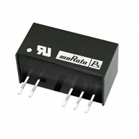
NMJ Series
5.2kVDC Isolated 1W DC/DC Converters
SELECTION GUIDE
Order Code
NMJ0505SC NMJ0509SC NMJ0512SC NMJ0515SC NMJ1205SC NMJ1209SC NMJ1212SC NMJ1215SC NMJ0303SAC NMJ0503SAC NMJ0505SAC NMJ0509SAC NMJ0512SAC NMJ0515SAC NMJ1205SAC NMJ1209SAC NMJ1212SAC NMJ1215SAC
Nominal Input Voltage V
5 5 5 5 12 12 12 12 3.3 5 5 5 5 5 12 12 12 12
Output Voltage V
±5 ±9 ±12 ±15 ±5 ±9 ±12 ±15 3.3 3.3 5 9 12 15 5 9 12 15
Output Current mA
±100 ±55 ±42 ±33 ±100 ±55 ±42 ±33 303 303 200 111 83 66 200 111 83 66
Ripple & Noise4 mV p-p
40 30 20 20 40 30 20 20 70 60 50 50 50 50 50 50 50 50
Efficiency Isolation (Min.) Capacitance %
60 65 65 65 60 65 65 65 66 64 68 72 71 71 69 73 73 74
MTTF1 kHrs
4950 3832 2770 1903 3688 3029 2324 1682 13780 13460 13360 12700 11490 9980 8447 8176 7660 6950
pF
3.0 3.0 3.0 3.0 3.0 3.0 3.0 3.0 3.0 3.0 3.0 3.0 3.0 3.0 3.0 3.0 3.0 3.0
FEATURES
RoHS compliant UL60950 recognized Power density 0.42W/cm3 Wide temperature performance at full 1 watt load, –40°C to 60°C Single and dual outputs UL 94V-0 package material No heatsink required Footprint 1.91cm2 SIP package style 5.2kVDC isolation 3V, 5V & 12V input 3V, 5V, 9V, 12V and 15V output Internal SMD construction Fully encapsulated with toroidal magnetics Pin compatible with the NMV series SIP DC/DC converters MTTF up to 13 million hours Custom solutions available
Contact Factory
When operated with additional external load capacitance the rise time of the input voltage will determine the maximum external capacitance value for guaranteed start up. The slower the rise time of the input voltage the greater the maximum value of the additional external capacitance for reliable start up.
INPUT CHARACTERISTICS
Parameter
Voltage range
Conditions
Continuous operation, 3V input types Continuous operation, 5V input types Continuous operation, 12V input types
Min.
2.97 4.5 10.8
Typ.
3.3 5 12
Max.
3.63 5.5 13.2
Units V
OUTPUT CHARACTERISTICS
Parameter
Rated Power2 Voltage Set Point Accuracy Line regulation Load regulation Single outputs
Conditions TA=-40ºC to 60ºC
See tolerance envelopes High VIN to low VIN 10% load to rated load, xx03 10% load to rated load, 0505 10% load to rated load, 0509, 0512, 0515 10% load to rated load, 12xx 10% load to rated load, 5V output types 10% load to rated load, 9V output types 10% load to rated load, 12V output types 10% load to rated load, 15V output types All types
Min.
Typ.
Max.
1
Units
W %/%
PRODUCT OVERVIEW
The NMJ series are dual and single output DC/DC converters in a 7 pin SIP package style offering pin and functionality compatibility with the NMV series SIP DC/DC converters. The NMJ series is UL60950 recognized and suitable for applications where safety and miniaturisation are of paramount importance. Isolation barrier approved for supplementary/reinforced insulation - see page 2.
Load regulation Dual outputs
Zero Load Power Consumption
1.0 10.0 7.0 6.0 5.0 10.0 6.0 6.0 6.0 250
1.2 15.0 10.0 10.0 7.0 15.0 10.0 10.0 10.0
%
%
mW
ABSOLUTE MAXIMUM RATINGS
Short-circuit protection3 Lead temperature 1.5mm from case for 10 seconds Input voltage VIN, NMJ03 types Input voltage VIN, NMJ05 types Input voltage VIN, NMJ12 types 1 second 300°C 5V 7V 15V
For full details go to www.murata-ps.com/rohs
1. Calculated using MIL-HDBK-217 FN2 calculation model with nominal input voltage at full load. 2. See derating graph. 3. Supply voltage must be discontinued at the end of the short circuit duration. 4. See ripple & noise test method. All specifications typical at TA=25°C, nominal input voltage and rated output current unless otherwise specified.
www.murata-ps.com
Technical enquiries - email: mk@murata-ps.com, tel: +44 (0)1908 615232
KDC_NMJC.G02 Page 1 of 6
�NMJ Series
5.2kVDC Isolated 1W DC/DC Converters
ISOLATION CHARACTERISTICS
Parameter
Isolation test voltage Resistance
Conditions
Flash tested for 1 second Viso= 500VDC
Min.
5200
Typ.
1
Max.
Units
VDC GΩ
GENERAL CHARACTERISTICS
Parameter
Switching frequency
Conditions
Single output Dual output
Min.
Typ.
45 70
Max.
Units
kHz
TEMPERATURE CHARACTERISTICS
Parameter
Specification Storage Case Temperature above ambient Cooling
Conditions
All output types All output types Free air convection
Min.
-40 -55
Typ.
Max.
60 130 33
Units
°C
TEMPERATURE DERATING GRAPH 1.5
TOLERANCE ENVELOPE +10% +6%
TOLERANCE ENVELOPE, 3.3V in, 3V out type only +9%
Output Power (W)
1.0 0.5 0 -40 Safe Operating Area
60ºC
Typical L
oad Line
+2.5%
Typical L
VNOM
Output Voltage
Output Voltage
-4% -7.5%
VNOM
+1% -7%
oad Lin
e
+1% -7% -15%
0 40 Ambient Temperature (ºC)
80
10
75 50 25 Output Load Current (%)
100
10
75 50 25 Output Load Current (%)
100
TECHNICAL NOTES
ISOLATION VOLTAGE ‘Hi Pot Test’, ‘Flash Tested’, ‘Withstand Voltage’, ‘Proof Voltage’, ‘Dielectric Withstand Voltage’ & ‘Isolation Test Voltage’ are all terms that relate to the same thing, a test voltage, applied for a specified time, across a component designed to provide electrical isolation, to verify the integrity of that isolation. Murata Power Solutions NMJ series of DC/DC converters are all 100% production tested at their stated isolation voltage. This is 5.2kVDC for 1 second. A question commonly asked is, “What is the continuous voltage that can be applied across the part in normal operation?” The NMJ series has been recognized by Underwiters Laboratory to 300Vrms for Supplementary Insulation and 150Vrms for Reinforced Insulation. REPEATED HIGH-VOLTAGE ISOLATION TESTING It is well known that repeated high-voltage isolation testing of a barrier component can actually degrade isolation capability, to a lesser or greater degree depending on materials, construction and environment. We therefore strongly advise against repeated high voltage isolation testing, but if it is absolutely required, that the voltage be reduced by 20% from specified test voltage.
SAFETY APPROVAL
The NMJ series has been recognised by Underwriters Laboratory (UL) to UL 60950 for supplementary insulation up to 300Vrms and reinforced insulation up to 150Vrms at a maximum ambient temperature of 60ºC. File number E179522 applies.
RoHS COMPLIANCE INFORMATION
This series is compatible with RoHS soldering systems with a peak wave solder temperature of 300ºC for 10 seconds. The pin termination finish on this product series is Tin Plate, Hot Dipped over Matte Tin with Nickel Preplate. The series is backward compatible with Sn/Pb soldering systems. For further information, please visit www.murata-ps.com/rohs
www.murata-ps.com
Technical enquiries - email: mk@murata-ps.com, tel: +44 (0)1908 615232
KDC_NMJC.G02 Page 2 of 6
�NMJ Series
5.2kVDC Isolated 1W DC/DC Converters
OUTPUT RIPPLE REDUCTION
By using the values of inductance and capacitance stated, the output ripple at the rated load is lowered to 5mV p-p max. Component selection Capacitor: It is required that the ESR (Equivalent Series Resistance) should be as low as possible, ceramic types are recommended. The voltage rating should be at least twice (except for 15V output), the rated output voltage of the DC/DC converter. Inductor: The rated current of the inductor should not be less than that of the output of the DC/DC converter. At the rated current, the DC resistance of the inductor should be such that the voltage drop across the inductor is 20MHz.
L Power Source
DC
C Load
DC
L, μH 3.3V single output types 5V single output types 9V single output types 12V single output types 15V single output types
Inductor Through Hole
SMD Consult Factory Consult Factory Consult Factory Consult Factory Consult Factory
+VOUT L
C, μF
Capacitor Size
V rating, V
Power Source
DC DC
C OV C -VOUT L
Load Load
5V dual output types 9V dual output types 12V dual output types 15V dual output types
L, μH 22 68
Inductor Through Hole 22R223C 22R224C
SMD 82223C Consult Factory 82224C Consult Factory
C, μF 4.70 0.47
Capacitor Size 1206 0805
V rating, V 10 25
www.murata-ps.com
Technical enquiries - email: mk@murata-ps.com, tel: +44 (0)1908 615232
KDC_NMJC.G02 Page 3 of 6
�NMJ Series
5.2kVDC Isolated 1W DC/DC Converters
OUTPUT RIPPLE REDUCTION (continued)
SMD option 8200 Inductor Series Mechanical Dimensions Through hole option 2200R Inductor Series Mechanical Dimensions
0.283±0.020 (7.2±0.50)
2.0 (0.080) ±0.3 (0.012)
2.5 (0.098) ±0.2 (0.008)
0.7 (0.028) Min.
332C
103C
3.2 (0.126) ±0.3 (0.012)
2.5 (0.0984) ±0.2 (0.008)
0.335±0.020 (8.5±0.50)
Recommended pad layout
3.81 (0.15) 1.52 (0.060)
1.614±0.130 (41.00±3.30)
0.413 (10.50) Max.
3.05 (0.120)
0.024±0.002 (0.60±0.05)
Recommended footprint
Ø0.047
+0.006 +0.15 Ø1.20 -0.000 -0.00
0.118(3.00)
All dimensions in inches (mm).
All dimensions in inches (mm).
For more information please visit www.murata-ps.com
www.murata-ps.com
Technical enquiries - email: mk@murata-ps.com, tel: +44 (0)1908 615232
KDC_NMJC.G02 Page 4 of 6
1.772±0.130 (45.00±3.30)
�NMJ Series
5.2kVDC Isolated 1W DC/DC Converters
CHARACTERISATION TEST METHODS
Ripple & Noise Characterisation Method
Ripple and noise measurements are performed with the following test configuration.
C1 C2 C3 R1 R2 T1 RLOAD R3
1uF X7R multilayer ceramic capacitor, voltage rating to be a minimum of 3 times the output voltage of the DC/DC converter 10uF tantalum capacitor, voltage rating to be a minimum of 1.5 times the output voltage of the DC/DC converter with an ESR of less than 100mΩ at 100 kHz 100nF multilayer ceramic capacitor, general purpose 450Ω resistor, carbon film, +/-1% tolerance 50Ω BNC termination 3T of the coax cable through a ferrite toroid Resistive load to the maximum power rating of the DC/DC converter. Connections should be made via twisted wires 50Ω resistor, carbon film, +/-1%
Measured values are multiplied by 10 to obtain the specified values.
Differential Mode Noise Test Schematic
DC/DC Converter OSCILLOSCOPE
C1 C2 C3 +
SUPPLY Input
R1
T1
R2
Y INPUT
+
Output
-
-
R LOAD
www.murata-ps.com
Technical enquiries - email: mk@murata-ps.com, tel: +44 (0)1908 615232
KDC_NMJC.G02 Page 5 of 6
�NMJ Series
5.2kVDC Isolated 1W DC/DC Converters
PACKAGE SPECIFICATIONS
MECHANICAL DIMENSIONS
0.77 (19.50)
PIN CONNECTIONS
Dual Output Pin Function
+VIN -VIN -VOUT OV +VOUT
Single Output Pin
1 2 5 7
Function
+VIN -VIN -VOUT +VOUT
0.39 (9.80)
1 2 5 6 7
0.49 (12.50)
RECOMMENDED FOOTPRINT DETAILS
x5 HOLES Ø 0.045 (1.15) 0.039 (1.00) 0.004 (0.10)
0.18 (4.60) 1 0.14 (3.60)
2
5
6*
7
0.022 (0.55) 0.018 (0.45) 0.022 (0.55) 0.018 (0.45)
*
0.1 (2.54)
0.1 (2.54)
Weight: 4.3g
0.1 (2.54)
0.094 (2.40) 0.012 (0.30) 0.008 (0.20)
* Hole not required for single output variants. All dimensions in inches ±0.01 (mm ±0.25mm).
0.074±0.03 (1.88±0.75)
TUBE OUTLINE DIMENSIONS
All dimensions in inches ±0.01 (mm ±0.25mm). All pins on a 0.1 (2.54) pitch and within ±0.01 (0.25) of true position. * Pin not fitted on single output variants.
Unless otherwise stated all dimensions in inches ±0.02 (mm ±0.5mm). Tube length : 20.669±0.079 (525mm±2mm).
Tube Quantity : 25
USA: UK: France: Japan:
Mansfield (MA), Tel: (508) 339-3000, email: sales@murata-ps.com Milton Keynes, Tel: +44 (0)1908 615232, email: mk@murata-ps.com Montigny Le Bretonneux, Tel: +33 (0)1 34 60 01 01, email: france@murata-ps.com Tokyo, Tel: 3-3779-1031, email: sales_tokyo@murata-ps.com Osaka, Tel: 6-6354-2025, email: sales_osaka@murata-ps.com Website: www.murata-ps.jp Shanghai, Tel: +86 215 027 3678, email: shanghai@murata-ps.com Guangzhou, Tel: +86 208 221 8066, email: guangzhou@murata-ps.com
Canada: Toronto, Tel: (866) 740 1232, email: toronto@murata-ps.com
Murata Power Solutions, Inc. 11 Cabot Boulevard, Mansfield, MA 02048-1151 U.S.A. Tel: (508) 339-3000 (800) 233-2765 Fax: (508) 339-6356
www.murata-ps.com email: sales@murata-ps.com ISO 9001 REGISTERED
Murata Power Solutions, Inc. makes no representation that the use of its products in the circuits described herein, or the use of other technical information contained herein, will not infringe upon existing or future patent rights. The descriptions contained herein do not imply the granting of licenses to make, use, or sell equipment constructed in accordance therewith. Specifications are subject to change without notice. © 2008 Murata Power Solutions, Inc.
Germany: München, Tel: +49 (0)89-544334-0, email: munich@murata-ps.com
China:
www.murata-ps.com
Technical enquiries - email: mk@murata-ps.com, tel: +44 (0)1908 615232
KDC_NMJC.G02 Page 6 of 6
�