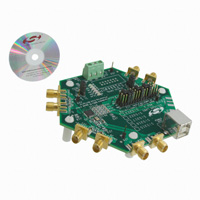
Si 5 3 1 7 - EVB
Si5317 E VALUATION B OARD U SER ’ S G U I D E
Description
The Si5317-EVB User’s Guide provides a complete and simple evaluation of the functions, features, and performance of the Si5317. The Si5317 is a pin-controlled 1:1 jitter-attenuating clock for high-performance applications. The Si5317 is based on Silicon Laboratories' 3rdgeneration DSPLL® technology, which provides anyrate jitter attenuation in a highly integrated PLL solution that eliminates the need for external VCXO and loop filter components. The DSPLL loop bandwidth is user programmable, providing jitter performance optimization at the application level.
Features
No software required. Simple jumpers for device configuration Fully powered from either a single USB port or an external power supply Selectable external reference clock or on-board crystal Status LEDs Header to connect to external test equipment for automated testing
Rev. 0.1 5/10
Copyright © 2010 by Silicon Laboratories
Si5317-EVB
�S i5317-EVB
1. Functional Block Diagram
A functional block diagram of the EVB is shown in Figure 1. The Si5317-EVB provides alarm and status outputs, programmable output clock signal format (LVPECL, LVDS, CML, CMOS), selectable loop bandwidths, and ultra low jitter. The Si5317 accepts a single clock input ranging from 1 MHz to 710 MHz and generates two equal frequency clock outputs ranging from 1 to 710 MHz. The clock frequency range and loop bandwidth are selectable from a simple look-up table. The Si5317-EVB has a differential clock input that is AC terminated to 50 and then AC-coupled to the Si5317. The two clock outputs are AC-coupled. The XA-XB reference is usually a 114.285 MHz crystal; but there are provisions for an external XA-XB reference (either differential or single-ended). The device status are available on a ribbon header and LEDs. Control pins are strapped using jumper headers for device configuration and various board options. The board can be powered using either external power supplies or from a PC's USB port. Refer to the Si5317 data sheet for technical details of the device.
Term*
XA
XB
CKOUT1+ Term* CKOUT1-
CKIN+ Term* CKINCKOUT2+ Term* CKOUT2-
Si5317
Control FRQTBL FRQSEL[3:0] BWSEL[1:0] RATE[1:0]
VDD GND
3.3V
Header
DUT Power USB + Regulator Status/ Control
2x15 JUMPER HEADER
SFOUT[1:0] DBL2_BY
INC DEC LOS LOL RST_B
2x5 JUMPER HEADER
L E D
Figure 1. Si5317 EVB Block Diagram
2
Rev. 0.1
�S i5317-EVB
2. Si5317-EVB Input and Output Clocks
2.1. Input Clocks
The Si5317-EVB has a differential clock input that is ac terminated and ac coupled before being presented to the Si5317. If the input clock frequencies are low (below 10 MHz), there are extra considerations that should be taken into account. The Si5317 has a maximum clock input rise time specification of 11 ns that must be met (see CKNtrf in the Si5317 data sheet). Also, if the input clock is LVCMOS, it might be advantageous to replace the input coupling capacitors (C7, C12, C16. and C18) with 0 resistors. When using LVCMOS inputs, the user should consider removing the ac termination and using source series termination located at the driving source. Regardless of the input format, if the clock inputs are not approximately 50% duty cycle, it is highly recommended to avoid ac coupling. For input clocks that are far off of 50% duty cycle, the average value of the signal that passes through the coupling capacitor will be significantly off of the midpoint between the maximum and minimum value of the clock signal, resulting in a mismatch with the common mode input threshold voltage (see Vicm, in the Si5317 data sheet).
2.2. XA-XB Reference
To achieve a very low jitter generation and for stability during holdover, the Si5317 requires a stable, low jitter reference at its XA-XB pins. To that end, the EVB is configured with a 114.285 MHz third overtone crystal connected between pins 6 and 7 of the Si5317. However, the Si5317-EVB is also capable of using an external XAXB reference oscillator, either differential or single-ended. For details concerning the allowed XA-XB reference frequencies and their RATE settings, see the Si5317 data sheet. J1 and J2 are the SMA connectors with ac termination. AC coupling is also provided that needs to be installed at C6 and C8. Table 1 explains the component changes that are needed to implement an external XA-XB reference oscillator.
Table 1. XA-XB Reference Connections
Mode Xtal Ext Ref In+ Ext Ref InC6, C8 R8 RATE0(See note 4) RATE1(See note 4)
Notes: 1. Xtal is 114.285 MHz. 2. NC - no connect. 3. NOPOP - do not install. 4. J12 jumper, see Table 3. 5. C6 on bottom of the board.
Ext Ref J1 J2 install NOPOP H M
NC NC NOPOP install M M
Rev. 0.1
3
�S i5317-EVB
2.3. Output Clock
The clock outputs are AC-coupled and are available on SMAs J5, J7, J9 and J11. For LVCMOS outputs, it might be desirable to replace the AC coupling capacitors (C9,C14,C17, and C20) with 0 resistors. Also, if greater drive strength is desired for an LVCMOS output, R6 and R10 can be installed.
2.4. Pin Configuration
J12 is the large jumper header in the center left of the board that implements the jumper plugs that configure the pins of the Si5317. Each pin can be strapped to become either H, M, or L. The H level is achieved by installing a jumper plug between the appropriate middle row pin and its VDD row pin. L is achieved by installing a jumper plug between the appropriate middle row pin and its GND row pin. M is achieved by installing no jumper plug.
2.5. Evaluation Board Power
The EVB can be powered from two possible sources: USB or external supplies. A 3.3 V supply is required to run the LEDs because of their rather large forward drop. The Si5317 power supply can be separated from the 3.3 V supply so that the Si5317 can be evaluated at a voltage other than 3.3 V. It is important to note that when the USB supply is being used, the EVB uses the USB port only for power and that the resulting power supply is strictly 3.3 V. Here are the instructions for the various possibilities: 2.5.1. External Power Supplies Install a jumper between J16.1 and J16.2 (labeled EXT). There should be no USB connection. If the Si5317 is not being operated at 3.3 V, two supplies should be connected to J14. Connect the 3.3 V supply to J14.1 and J14.2 (labeled 3.3 V and GND). Connect the SI5317 power supply between J14.2 and J14.3 (labeled GND and DUT). If the Si5317 is to be operated at 3.3 V, J15 (labeled ONE PWR) can be installed, requiring only one external supply. Connect 3.3 V power between J14.2 and J14.3 (labeled GND and DUT). 2.5.2. USB Power Install a jumper between J16.2 and J16.3 (labeled USB). Install a jumper at J15 (labeled ONE PWR). With a USB cable, plug the EVB into a powered USB port. 2.5.3. USB 3.3V Power, External Si5317 Power Install a jumper between J16.2 and J16.3 (labeled USB). No jumper at J15 (labeled ONE PWR). Connect the Si5317 power supply between J14.2 and J14.3 (labeled GND and DUT).
4
Rev. 0.1
�S i5317-EVB
3. Connectors and LEDs
3.1. LEDs
Table 2. LED Descriptions
LED D1 D2 D3 D4 D5 D6 Label CS_CA LOS2 LOS1 LOL DUT_PWR 3.3V Not used Not used ON = no valid clock input ON = Si5317 is not locked ON = Si5317 power is present ON = 3.3 V power is present Significance
3.2. Jumpers, Headers, and Connectors
Refer to Figure 2 to locate the items described in this section.
J12
C8, R8
Si5317
J16
J13 J14
J15
Figure 2. EVB Jumper Locations
Rev. 0.1
5
�S i5317-EVB
Table 3. Configuration Header, J12
J12 J12.1 J12.2 J12.3 J12.4 J12.5 J12.6 J12.7 J12.8 J12.9 J12.10 J12.11 J12.12 J12.13 J12.14 Pin not used SFOUT0 SFOUT1 FRQSEL0 FRQSEL1 FRQSEL2 FRQSEL3 FRQTBL BWSEL0 BSWEL1 DBL2_BY not used RATE0 RATE1
Table 4. Status Indication Header, J13
J13 J13.1 J13.3 J13.5 J13.7 J13.9 J13.11 J13.13 Signal INC DEC LOS Not used Not used LOL RST_B
6
Rev. 0.1
�Ext Ref In +
DUT_PWR
J1 SMA_EDGE 1
2
3
to power plane
L1 NOPOP 100 R1 Ferrite R2 0 ohm R3 R4
to measure DUT supply
2
Ext Ref In 1 2
C9 J3 NOPOP J5 SMA_EDGE 1
J2 SMA_EDGE 1
1
2
3
CKOUT1+
3
4. Schematic
C1 10NF NOPOP C5 1UF C6 10NF NOPOP C8 10NF NOPOP 100N C14 J7 SMA_EDGE 1 C4 100N R6 0 ohm R5 C3 10NF
C2 10NF
FILT_DUT_PWR
J4 SMA_EDGE 1
49.9
CKIN1+ CKOUT13 2
2
3
100N C7
2
49.9
49.9
100N
CKIN10 ohm
J6 SMA_EDGE 1
see option l
2
3
100N C12
see option list
R8 C17 X1
C11 100N
C10 100N
C13 10NF R7
optionally install for CMOS outputs
J9 SMA_EDGE 1 100N NOPOP R10 0 ohm
49.9
CKOUT2+
3 2
J11 SMA_EDGE 1
J8 SMA_EDGE 1 C15
49.9 R9
2 GND 6 7 XA XB CKIN1+ CKIN1CKOUT1+ CKOUT128 29 CKIN_2+ CKIN_2CKOUT2+ CKOUT2Rate1 Rate0 35 34 16 17 12 13 15 11 VDD1 VDD2 VDD3
114.285 MHz
4
CKIN2+
10NF
2
3
100N C16
5 10 32
option list
1
3
CKOUT23
C20 100N
J10 SMA_EDGE 1
CKIN2C19 10NF NOPOP 0 ohm U1 R13 R12 0 ohm
2
3
100N C18
2
49.9 R11
LOS2 LOS1
J12
Si5315/17
INC DEC SFOUT1 SFOUT0 LOS1 LOS2 20 19 30 33 3 4
1C
DUT_PWR
14x3_M_HDR_THRU 10
R15 10k
TP2
R14
2
1
S i5317-EVB
Figure 3. Si5317-EVB
8 31 37
14A 14B 13A 13B 12A 12B 11A 11B 10A 10B 9A 9B 8A 8B 7A 7B 6A 6B 5A 5B 4A 4B 3A 3B 2A 2B 1A 1B
RST
1
GND1 GND2 GND3
Rev. 0.1
see option list
9 AUTOSEL DBL2_BY BWSEL1 BWSEL0 FRQTBL FRQSEL3 FRQSEL2 FRQSEL1 FRQSEL0 NC 1 LOL 18 CS_CA 21 14 23 22 2 27 26 25 24
DUT_PWR TP1
14C
RATE1
13C
RATE0
12C
Status, Control
14_M_Header
AUTOSEL
11C
DBL2_BY
10C
BWSEL1
9C
BWSEL0
mper ugs
8C
FRQTBL
INC DEC LOS1 LOS2 CS_CA LOL RST_B
1 3 5 7 9 11 13
J13
2 4 6 8 10 12 14
7C
INC DEC LOS1 LOS2 CS_CA LOL RST_B
FRQSEL3
6C
FRQSEL2
5C
CS_CA
FRQSEL1
4C 36 2
FRQSEL0
3C
LOL
SFOUT1
2C
SFOUT0
7
�1
1
1
DUT_PWR
EVB main power
+
C21 220UF
C22 1UF
mounting holes
Single 3.3V supply
J14
J15
S i5317-EVB
DUT_PWR
3
1 2
GND
U2 FAN1540B
2 1 NC1 VOUT PAD VIN 7 NC3 NC2 GND 1 2 3
USB_3P3V J16
install jumper to run DUT from 3.3V
Power Source Selection
6 5 4 2 3
+ C23 33UF
3.3V
* * *
select 3.3V from either USB or from J14
Ferrite
1
Phoenix_3_screw
PHOENIX_3P3V
L2 1
2
J17 USB
V3P3
C25 1UF
C24 220UF +
1
S2
S1
6
RAW_3P3V
LED_PWR
150 A
R17
Yel 2C
D1 1
CS_CA
Q1 CS_CA
3
1 2
BSS138 Red
150
R18
1C
A D2
2
LOS2
3
Q2 LOS2 Red
see option list
1C
A D3
2
3
2
Q4 LOL
3
2
DUT_PWR
Q5
1
R20 10k
2
BSS138
3
Rev. 0.1
2 1
BSS138
LOS1
1
J18
5
8
DUT Power
H1 #4 #4 #4 #4 H2 H3 H4 DUT_PWR
USB power
2 DD+ Gnd 4
+
V
1
VBUS C26 33UF
3
0 ohm R16
1C
Red A D4
2
LOL
ground pins
1 1 1
J19 J20 J21
Q3
1 2 3 4 2
C Grn D5 A
8 7 6 5 1
DUT_PWR
1 1 1
J22 J23 J24
LOS1 BSS138 R150x4 R19
1
2
C D6 Grn
A
1
3.3V
1 1
J25 J26
1
BSS138
Figure 4. LED and Power/USB
�S i5317-EVB
5. Bill of Materials
Item 1 Qty 6 Reference C1,C2,C3, C13,C15, C19 C4,C7,C9, C10,C11, C12,C14, C16,C17, C18,C20 3 5 6 7 8 9 11 3 2 2 1 3 2 10 C5,C22,C25 C21,C24 C23,C26 D1 D2,D3,D4 D5,D6 J1,J2,J4,J5, J6,J7,J8,J9, J10,J11 13 15 16 17 18 19 20 21 1 1 1 1 1 4 2 5 J12 J14 J15 J16 J17 J19,J20,J24, J26 L1,L2 Q1,Q2,Q3, Q4,Q5 14x3_M_H DR_THRU Phoenix_3 _screw Jmpr_2pin Jmpr_3pin USB Jmpr_1pin Ferrite BSS138 Venkel On Semi FBC1206-471H BSS138LT1G BSS138L T10SCTND FCI 61729-0010BLF 609-1039ND 3pin_p1pitch USB_typeB 1pin_p1pitch 1206 SOT23 any Phoenix two and one row side by side MKDSN 1.5/35.08 20x3_M_HDR_THRU 277-1248- Phoenix3pinM_p2pitch ND 1UF 220UF 33UF Yel Red Grn SMA_ EDGE Venkel Kemet Venkel Panasonic Lumex Panasonic Johnson C0603X7R6R3105KNE T494B227M004A T TA006TCM336M BR LN1471YTR LN1271RAL LN1371G 142-0701-801 P11125CT -ND P493CTND P491CTND J502-ND 399-46311-ND 603 SM_C_3528_21 3528 LED_gull LED_gull LED_gull SMA_EDGE_p062 Part 10NF Mfr Venkel MfrPartNum C0603X7R160103KNE C0603X7R160104KNE BOM Digikey Footprint 603
2
11
100N
Venkel
603
Rev. 0.1
9
�S i5317-EVB
Item 23 24 26 27 28 29 31 32 Qty 4 6 1 2 2 1 1 1 Reference R2,R8,R13, R16 R3,R4,R5, R7,R9,R11 R14 R15,R20 R17,R18 R19 U1 U2 Part 0 ohm 49.9 10 10k 150 R150x4 Si5317 FAN1540B Mfr Venkel Venkel Venkel Venkel Venkel Panasonic Silicon Labs Fairchild MfrPartNum CR0603-16W000T CR0603-16W49R9FT CR0603-16W10R0FT CR603-16W1002FT CR0603-16W1500FT EXB-38V151JV Si5317A-C-GM FAN1540BPMX FAN1540 BMPXCTND Y9151CTND BOM Digikey Footprint 603 603 603 603 603 1206x4 QFN-36 MLP6
33 34 35
1 3 3
X1
114.285 MHz standoff spacer
TXC SPC Tech Richco
7MA1400014 2397 NSS-4-4-01
xtal 3.2 x 2.5
4 12 22 25 30 14 19
2 1 1 3 2 1 9
C6,C8 J3 R1 R6,R10,R12 TP1,TP2 J13 J18,J21,J22, J23,J25
10NF Jmpr_2pin 100 0 test_points 14_M_ Header Jmpr_1pin
Venkel
C0603X7R160103KNE
NOPOP NOPOP
603
Venkel Venkel
CR0603-16W1000FT CR0603-16W000T
NOPOP NOPOP NOPOP
603 603
3M
N2514-6002RB
NOPOP MHC14K- 14pinMdualHeader_p1 ND pitch NOPOP 1pin_p1pitch
10
Rev. 0.1
�S i5317-EVB
6. Layout
Figure 5. Silkscreen Top
Rev. 0.1
11
�S i5317-EVB
Figure 6. Layer 1
12
Rev. 0.1
�S i5317-EVB
Figure 7. Layer 2—Ground Plane
Rev. 0.1
13
�S i5317-EVB
Figure 8. Layer 3
14
Rev. 0.1
�S i5317-EVB
Figure 9. Layer 4
Rev. 0.1
15
�S i5317-EVB
Figure 10. Layer 5, FILT_DUT_PWR
16
Rev. 0.1
�S i5317-EVB
Figure 11. Layer 6, Bottom
Rev. 0.1
17
�S i5317-EVB
Figure 12. Bottom Silkscreen
18
Rev. 0.1
�S i5317-EVB
7. Factory Default Configuration
J12 J12.1 J12.2 J12.3 J12.4 J12.5 J12.6 J12.7 J12.8 J12.9 J12.10 J12.11 J12.12 J12.13 J12.14 The above jumper settings result in the following:
Pin not used SFOUT0 SFOUT1 FRQSEL0 FRQSEL1 FRQSEL2 FRQSEL3 FRQTBL BWSEL0 BSWEL1 DBL2_BY not used RATE0 RATE1
Jumper — H L L M M H L M H L — M M
SFOUT = CMOS output 10.0 MHz input clock 10.0 MHz output clock BW =88 Hz RATE[1:0] = 114.285 MHz 3rd overtone crystal
Rev. 0.1
19
�S i5317-EVB
CONTACT INFORMATION
Silicon Laboratories Inc. 400 West Cesar Chavez Austin, TX 78701 Tel: 1+(512) 416-8500 Fax: 1+(512) 416-9669 Toll Free: 1+(877) 444-3032 Please visit the Silicon Labs Technical Support web page: https://www.silabs.com/support/pages/contacttechnicalsupport.aspx and register to submit a technical support request.
The information in this document is believed to be accurate in all respects at the time of publication but is subject to change without notice. Silicon Laboratories assumes no responsibility for errors and omissions, and disclaims responsibility for any consequences resulting from the use of information included herein. Additionally, Silicon Laboratories assumes no responsibility for the functioning of undescribed features or parameters. Silicon Laboratories reserves the right to make changes without further notice. Silicon Laboratories makes no warranty, representation or guarantee regarding the suitability of its products for any particular purpose, nor does Silicon Laboratories assume any liability arising out of the application or use of any product or circuit, and specifically disclaims any and all liability, including without limitation consequential or incidental damages. Silicon Laboratories products are not designed, intended, or authorized for use in applications intended to support or sustain life, or for any other application in which the failure of the Silicon Laboratories product could create a situation where personal injury or death may occur. Should Buyer purchase or use Silicon Laboratories products for any such unintended or unauthorized application, Buyer shall indemnify and hold Silicon Laboratories harmless against all claims and damages. Silicon Laboratories, Silicon Labs, and DSPLL are trademarks of Silicon Laboratories Inc. Other products or brandnames mentioned herein are trademarks or registered trademarks of their respective holders.
20
Rev. 0.1
�