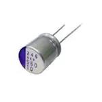
Conductive Polymer Aluminum
Solid Capacitors
Radial Lead Type
SEP series
Features
● Standard
● 105 ℃ 3000 h
● RoHS compliance, Halogen free
Specifications
Size code
C6
E7
E12
Category temp. range
Rated voltage range
Nominal cap.range
4.0 V to 20 V
22 μF to 150 μF
33 μF to 330 μF
Capacitance tolerance
Dissipation factor (tan δ)
4.0 V to 20 V
2.5 V to 20 V
100 μF to 680 μF
56 μF to 680 μF
150 μF to 1500 μF
Please see the attached characteristics list
+105 ℃ 3000 h, rated voltage applied (2.5 V products : 2000 h)
Capacitance change
Within ±20 % of the initial value
Dissipation factor (tanδ)
DC leakage current
Damp heat
(Steady state)
≦ 150 % of the initial limit
Within the initial limit
+60 ℃, 90 % to 95 % RH, 1000 h, No-applied voltage
Capacitance change
Within ±20 % of the initial value
Dissipation factor (tanδ)
DC leakage current
Marking
≦ 150 % of the initial limit
Within the initial limit (after voltage processing)
Dimensions (not to scale)
Polarity marking (−)
ød
⊕
øD
Series code*
F
Lot No.
15 min.
L
R. voltage
(V)
* Depends on the case size.
F13
±20 % (120 Hz / +20 ℃)
Please see the attached characteristics list
DC leakage current
Endurance
F8
–55 ℃ to +105 ℃
2.5 V to 20 V
R. capacitance
(μF)
⊖
4 min.
19 min.
Unit:mm
Size code
C6
E7
E12
F8
F13
øD±0.5
6.3
8.0
8.0
10.0
10.0
L max.
6.0
7.0
12.0
8.0
13.0
Design and specifications are each subject to change without notice. Ask factory for the current technical specifications before purchase and/or use.
Should a safety concern arise regarding this product, please be sure to contact us immediately.
F±0.5
2.5
3.5
3.5
5.0
5.0
ød±0.05
0.45
0.45
0.6
0.5
0.6
01-Nov-15
�SEP series
Characteristics list
Case size
Rated
voltage
(V)
2.5
(±20 %)
(μF)
Specifications
(mm)
Rated
capacitance
øD
L
Size
code
Ripple
current *1
(mA rms)
ESR*2
(mΩ max.)
tan δ*3
Part number
LC*4
(μA)
Click here for part number
list of lead terminal cutting
and lead terminal taping
680
8.0
12.0
E12
4520
13
0.15
340
2R5SEP680M
1500
10.0
13.0
F13
5440
12
0.18
750
2R5SEP1500M
100
6.3
6.0
1810
40
0.12
200
4SEP100M
150
6.3
6.0
1810
40
0.12
300
4SEP150M
220
8.0
7.0
2560
35
0.12
440
4SEP220M
330
8.0
7.0
2560
35
0.12
660
4SEP330M
470
10.0
8.0
F8
3700
25
0.12
376
4SEP470M
560
8.0
12.0
E12
4520
13
0.15
448
4SEP560M
680
10.0
8.0
F8
3700
25
0.12
544
4SEP680M
1200
10.0
13.0
F13
5440
12
0.18
960
4SEP1200M
4.0
6.3
10
16
C6
E7
82
6.3
6.0
C6
1700
45
0.12
258
6SEP82M
150
8.0
7.0
E7
2560
35
0.12
472
6SEP150M
330
10.0
8.0
F8
3700
25
0.12
416
6SEP330M
470
8.0
12.0
E12
4210
15
0.15
592
6SEP470M
820
10.0
13.0
F13
5440
12
0.15
775
6SEP820M
56
6.3
6.0
C6
1700
45
0.12
280
10SEP56M
120
8.0
7.0
E7
2560
35
0.12
600
10SEP120M
270
10.0
8.0
F8
3700
25
0.12
540
10SEP270M
330
8.0
12.0
E12
3950
17
0.15
660
10SEP330M
560
10.0
13.0
F13
5230
13
0.15
840
10SEP560M
39
6.3
6.0
C6
1620
50
0.10
312
16SEP39M
82
8.0
7.0
E7
2120
40
0.12
656
16SEP82M
150
10.0
8.0
F8
3020
30
0.12
480
16SEP150M
180
8.0
12.0
E12
3640
20
0.15
576
16SEP180M
330
10.0
13.0
F13
4720
16
0.15
792
16SEP330M
22
6.3
6.0
C6
1450
60
0.10
220
20SEP22M
33
8.0
7.0
1890
45
0.12
330
20SEP33M
47
8.0
7.0
1890
45
0.12
470
20SEP47M
56
10.0
8.0
2400
40
0.12
224
20SEP56M
68
10.0
8.0
2400
40
0.12
272
20SEP68M
10.0
8.0
2570
35
0.12
400
20SEP100MX
8.0
12.0
E12
3320
24
0.15
400
20SEP100M
10.0
13.0
F13
4320
20
0.15
600
20SEP150M
20
100
150
E7
F8
*1: Ripple current (100 kHz / +105 ℃)
*2: ESR (100 kHz to 300 kHz / +20 ℃)
*3: tan δ (120 Hz / +20 ℃)
*4: After 2 minutes
◆ Please refer to each page in this catarog for “Flow conditions” and “Taping specifications”.
Frequency correction factor for ripple current
Frequency(f)
Coefficient
120 Hz ≦ f < 1 kHz
0.05
1 kHz ≦ f < 10 kHz
0.3
10 kHz ≦ f < 100 kHz
0.7
Design and specifications are each subject to change without notice. Ask factory for the current technical specifications before purchase and/or use.
Should a safety concern arise regarding this product, please be sure to contact us immediately.
100 kHz ≦ f < 500 kHz
1
01-Nov-15
�SEP series
Packing specifications
◇ Radial lead type
● Lead terminal process
1-1. Correspondence list
※ The following table is a standard specification. Please contact us separately concerming specifications except for that mentioned below.
Series
Size code
SEP
C6, E7, E12
F8, F13
Bag-packed products (lead terminal cutting)
Not processed
No code
No code
Straight cut
+C3
+C3
Taping products
+TSS
+T
1-2. Lead terminal cutting specifications
Process names
Size code
Lead terminal
cutting code
Straight
cut
C6
E7, E12
F8, F13
+C3
Lead terminal dimensions
L
Unit:mm
3.5±0.5
1-3. Taping specifications for automatic insertion
Size code
Case size
F
Taping code
C6
ø6.3
F=2.5 mm
Taping dimensions
+TSS
E7, E12
ø8
F=3.5 mm
F8, F13
ø10
F=5.0 mm
Carrier tape
Hold-down tape
+T
Carrier tape
Hold-down tape
P
P0
P1
P2
Δh
W
W0
W1
W2
H
øD0
±1.0
±0.2
±0.5
±1.0
±1.0
±0.5
min.
±0.5
max.
±0.75
±0.2
2.5
12.7
12.7
5.10
6.35
0
18.0
9.5
9.0
2.5
17.5
4.0
ø8
3.5
12.7
12.7
4.60
6.35
0
18.0
9.5
9.0
2.5
17.5
4.0
ø10
5.0
12.7
12.7
3.85
6.35
0
18.0
9.5
9.0
2.5
18.5
4.0
Code
F
Tolerance
ø6.3
+TSS
+T
+0.8
-0.2
Code
t
ℓ
L
Tolerance
±0.3
max.
max.
ø6.3
0.6
0
11.0
ø8
0.6
0
11.0
ø10
0.6
0
11.0
+TSS
+T
Unit:mm
● Minimum packing quantity and weight
Bag-packed products
Taping products
Size
code
Case
size
Quantity(pcs./Bag)
Typical weight(g)
Quantity(pcs./Bag)
Typical weight(g)
C6
E7
E12
F8
F13
ø6.3
ø8
ø8
ø10
ø10
500
200
200
200
200
160
110
200
180
280
1500
1000
1000
500
500
700
820
980
890
940
Design and specifications are each subject to change without notice. Ask factory for the current technical specifications before purchase and/or use.
Should a safety concern arise regarding this product, please be sure to contact us immediately.
05-Mar-21
�SEP series
Radial lead (Lead terminal cutting / Lead terminal taping)
Series
SEP
No processing
Lead terminal cutting
10SEP120M
10SEP270M
10SEP330M
10SEP560M
10SEP56M
16SEP150M
16SEP180M
16SEP330M
16SEP39M
16SEP82M
20SEP100M
20SEP100MX
20SEP150M
20SEP22M
20SEP33M
20SEP47M
20SEP56M
20SEP68M
2R5SEP1500M
2R5SEP680M
4SEP100M
4SEP1200M
4SEP150M
4SEP220M
4SEP330M
4SEP470M
4SEP560M
4SEP680M
6SEP150M
6SEP330M
6SEP470M
6SEP820M
6SEP82M
10SEP120M+C3
10SEP270M+C3
10SEP330M+C3
10SEP560M+C3
10SEP56M+C3
16SEP150M+C3
16SEP180M+C3
16SEP330M+C3
16SEP39M+C3
16SEP82M+C3
20SEP100M+C3
20SEP100MX+C3
20SEP150M+C3
20SEP22M+C3
20SEP33M+C3
20SEP47M+C3
20SEP56M+C3
20SEP68M+C3
2R5SEP1500M+C3
2R5SEP680M+C3
4SEP100M+C3
4SEP1200M+C3
4SEP150M+C3
4SEP220M+C3
4SEP330M+C3
4SEP470M+C3
4SEP560M+C3
4SEP680M+C3
6SEP150M+C3
6SEP330M+C3
6SEP470M+C3
6SEP820M+C3
6SEP82M+C3
Lead terminal taping
10SEP120M+TSS
10SEP270M+T
10SEP330M+TSS
10SEP560M+T
10SEP56M+TSS
16SEP150M+T
16SEP180M+TSS
16SEP330M+T
16SEP39M+TSS
16SEP82M+TSS
20SEP100M+TSS
20SEP100MX+T
20SEP150M+T
20SEP22M+TSS
20SEP33M+TSS
20SEP47M+TSS
20SEP56M+T
20SEP68M+T
2R5SEP1500M+T
2R5SEP680M+TSS
4SEP100M+TSS
4SEP1200M+T
4SEP150M+TSS
4SEP220M+TSS
4SEP330M+TSS
4SEP470M+T
4SEP560M+TSS
4SEP680M+T
6SEP150M+TSS
6SEP330M+T
6SEP470M+TSS
6SEP820M+T
6SEP82M+TSS
29-Jul-20
�Safety and Legal Matters to Be Observed
Safety and Legal Matters to Be Observed
Product specifications and applications
■ Please be advised that this product and product specifications are subject to change without notice for
improvement purposes. Therefore, please request and confirm the latest delivery specifications that explain
the specifications in detail before the final design, or purchase or use of the product, regardless of the
application. In addition, do not use this product in any way that deviates from the contents of the company's
delivery specifications.
■ Unless otherwise specified in this catalog or the product specifications, this product is intended for use in
general electronic equipment (AV products, home appliances, commercial equipment, office equipment,
information and communication equipment, etc.).
When this product is used for the following special cases, the specification document suited to each application
shall be signed/sealed (with Panasonic Industry and the user) in advance..These include applications requiring
special quality and reliability, wherein their failures or malfunctions may directly threaten human life or cause harm
to the human body (e.g.: space/aircraft equipment, transportation/traffic equipment, combustion equipment,
medical equipment, disaster prevention/crime prevention equipment, safety equipment, etc.).
Safety design and product evaluation
■ Please ensure safety through protection circuits, redundant circuits, etc., in the customer's system design so
that a defect in our company's product will not endanger human life or cause other serious damage.
■ This catalog shows the quality and performance of individual parts. The durability of parts varies depending on
the usage environment and conditions. Therefore, please ensure to evaluate and confirm the state of each part
after it has been mounted in your product in the actual operating environment before use.
If you have any doubts about the safety of this product, then please notify us immediately, and be sure to conduct
a technical review including the above protection circuits and redundant circuits at your company.
Laws / Regulations / Intellectual property
■ The transportation of dangerous goods as designated by UN numbers, UN classifications, etc., does not apply
to this product. In addition, when exporting products, product specifications, and technical information described
in this catalog, please comply with the laws and regulations of the countries to which the products are exported,
especially those concerning security export control.
■ Each model of this product complies with the RoHS Directive (Restriction of the use of hazardous substances in
electrical and electronic equipment) (2011/65/EU and (EU) 2015/863). The date of compliance with the RoHS
Directive and REACH Regulation varies depending on the product model.
Further, if you are using product models in stock and are not sure whether or not they comply with the RoHS
Directive or REACH Regulation, please contact us by selecting "Sales Inquiry" from the inquiry form.
■ During the manufacturing process of this product and any of its components and materials to be used,
Panasonic Industry does not intentionally use ozone-depleting substances stipulated in the Montreal Protocol
and specific bromine-based flame retardants such as PBBs (Poly-Brominated Biphenyls) / PBDEs
(Poly-Brominated Diphenyl Ethers). In addition, the materials used in this product are all listed as existing
chemical substances based on the Act on the Regulation of Manufacture and Evaluation of Chemical Substances.
■ With regard to the disposal of this product, please confirm the disposal method in each country and region
where it is incorporated into your company's product and used.
■ The technical information contained in this catalog is intended to show only typical operation and application
circuit examples of this product. This catalog does not guarantee that such information does not infringe upon
the intellectual property rights of Panasonic Industry or any third party, nor imply that the license of such rights
has been granted.
■ Design, materials, or process related to technical owned by Panasonic Industry are subject to change without
notice.
Panasonic Industry will assume no liability whatsoever if the use of our company's
products deviates from the contents of this catalog or does not comply with the
precautions. Please be advised of these restrictions.
10-May-24
�Matters to Be Observed When Using This Product
Matters to Be Observed When Using This Product
(Conductive Polymer Aluminum Solid Capacitors / OS-CON)
Use environments and cleaning conditions
■ This product (capacitor) is intended for standard general-purpose use in electronic equipment, and is not designed for
use in the specific environments described below. Using the product in such specific environments or service conditions,
therefore, may affect the performance of the product.
Please check with us about the performance and reliability of the product first before using the product.
(1) Used in liquid, such as water, oil, chemicals, and organic solvents.
(2) Used in a place exposed to direct sunlight, an outdoor place with no shielding, or a dusty place.
(3) Used in a wet place (dew concentration on a resistor, water leakage, etc.), a place exposed to sea breeze, or a place
filled with a corrosive gas, such as Cl2, H2S, NH3, SO2, or NOX.
(4) Used in an environment where static electricity and electromagnetic waves are strong.
(5) The product is located close to a heating component or a flammable material, such as a vinyl cable, is placed near
the product.
(6) The product is used sealed with a resin, etc.
(7) Solder flux of the soldered product is cleansed with a solvent, water, and a water-soluble cleaner.
(Be careful with water soluble solder flux.)
(8) Used in an environment where an acidic or alkali atmosphere is present.
(9) Used in an environment where excessive vibration or impact is applied to the product.
(10) Used under a low atmospheric pressure condition or depressurized condition.
■ Cleaning can be performed with cleaning agents, including higher-grade alcohol-based cleaning solutions such as
Pine Alpha ST-100S, Cleanthru 750H, 750L, 710M, 750K, Techno Care FRW14-17, CFC substitutes such as
AK-225AES, and IPA. Please confirm the following precautions before cleaning.
(1) Use an immersion, ultrasonic wave, or other cleaning method, and the cleaning time should not exceed
2 minutes.
(2) The temperature of the cleaning solution should be less than or equal to 60°C.
(3) Control contamination of cleaning agents (conductivity, pH, specific gravity, water content, etc.).
(4) After cleaning, do not store the product in the atmosphere of the cleaning solution or in an airtight container.
(5) When drying the circuit board or this product, use hot air below the upper limit temperature of their category.
(6) Please be mindful that rubbing the printed surface of this product after cleaning may erase the markings
depending on the cleaning agent used.
(7) Please contact us separately for details on cleaning agents, cleaning methods, etc., and for cleaning
solutions other than those listed above.
■ Fixing agents and coating agents
(1) Select appropriate materials for the outer packaging and sealing materials of this product. Do not use acetone,
especially in fixing agents, coating agents, or diluents.
(2) When using a fixing agent or coating agent, ensure that no flux residue or contamination remains between
the circuit board and the sealing area of this product.
(3) Allow cleaning agents, etc. to dry before using fixing agents or coating agents.
(4) Please contact us for thermal curing conditions for fixing agents or coating agents.
■ When the capacitor is used in a circuit where an impact voltage is applied or a high voltage is applied in a short period
(transient phenomenon) or a high pulse voltage is applied, make sure to use the capacitor at a voltage equal to or
lower than its rated voltage.
30-Jun-23
�Matters to Be Observed When Using This Product
Response to anomalies and handling conditions
■ The main failure mode is a short-circuit mode caused mainly by thermal stress, electrical stress, and mechanical
stress due to soldering and operating temperature environments. To prevent the occurrence of short circuits, the
following measures should be adequately taken to ensure safety.
(1) If odorous gases are generated, then turn off the main power of the set equipment and stop using it.
In this case, keep your face and hands away from the equipment.
(2) Depending on conditions, it may take several seconds to several minutes before odorous gases are generated.
When using a protection circuit, design it so that it operates during this period.
(3) If odorous gases get into your eyes or are inhaled, immediately wash your eyes with water or gargle.
(4) Do not lick the electrolyte of the product. If the electrolyte gets on your skin, then wash it off with soap.
(5) When a current value after the short of the product is extremely large, the shorted capacitor may spark out,
which, in the worst scenario, may result in ignition. Ensure the safety of the circuit by, for example, giving it a
redundant circuit structure or providing it with a protective circuit.
Reliability and product life
The failure rate of the capacitor is specified based on 0.5%*/1000 h (reliability level 60%), a failure rate conforming to
JIS C 5003 (failure rate level). This indicates that the possibility of occurrence of a failure is by no means zero.
One of the failure modes is a wear out failure. This happens when the period of guaranteeing the durability and
high-temperature/high-humidity resistance of the capacitor is over, changes in the electrical characteristics of the
capacitor (product) get larger and its electrolyte gradually deteriorates into an insulating material to create an open mode.
Another failure mode is a random failure in which a short mode results mainly because of thermal, electrical,
or mechanical stress, etc.
Circuit design and circuit board design
■ Due to reasons such as increased leakage currents, do not use this product in high impedance circuits, coupling
circuits, time constant circuits, and circuits that are significantly affected by leakage currents.
■ During circuit design, be mindful that the electrical characteristics of this product, such as capacitance and ESR, may
fluctuate within the specified ranges even under conditions that meet the rated electrical and mechanical performance.
■ Leakage currents may increase due to mechanical and thermal stress (soldering, high-temperature no-load test, etc.).
However, when the voltage (lower than or equal to the category voltage and upper limit temperature) is applied,
leakage currents gradually decrease due to the self-recovery function.
■ If an excessive rush current flows due to rapid charging and discharging, then it may lead to short circuits and increased
leakage currents. Therefore, apply a protection circuit to this product if the rush current value flowing through it is as
follows.
(1) When a rush current of 10 A or more flows through a product whose tenfold allowable ripple current is less
than 10 A.
(2) With regard to a product whose tenfold allowable ripple current is 10 A or more, when a rush current exceeding
the tenfold value flows through the product.
■ The resin on the surface of the case does not guarantee insulation. In addition, there is an indefinite resistance between
the case and the cathode terminal, and they are not insulated. Therefore, completely isolate the case from the cathode
terminal, anode terminal, and circuit pattern.
Mounting and storage conditions
■ Soldering with a soldering iron
(1) Since the lead wire pitch dimension of the radial lead type capacitor and the printed circuit board hole pitch dimension
do not match, when processing the lead wires, do not apply stress to the body before soldering.
(2) When soldering, do not apply excessive stress to the body of this product.
(3) Once the product has been soldered, when using a soldering iron to remove it, remove it after the solder has
completely melted so as not to apply stress to the electrode terminals of the product.
(4) Do not allow the tip of the soldering iron to touch the body of this product.
30-Jun-23
�Matters to Be Observed When Using This Product / Reference Information
■ Flow soldering
(1) Do not apply flow soldering to the surface mount type model of this product.
(2) Do not solder this product by immersing its body in molten solder.
(3) Solder only on the opposite side of the circuit board surface where this product is mounted.
(4) Do not allow flux to adhere to parts other than the electrode terminals.
(5) Do not allow other parts to fall over and come into contact with this product during soldering.
■ Reflow soldering
(1) Do not apply reflow soldering to the radial lead type model of this product.
(2) Please contact us separately for soldering conditions for using the VPS method.
■ Handling after soldering
Observe the following precautions to avoid applying excessive stress on this product.
(1) Do not tilt, knock over, or twist this product.
(2) Do not move the circuit board by grabbing this product.
(3) Do not hit this product with objects.
(4) When stacking circuit boards, do not allow circuit boards or other parts to come in contact with this product.
■ It is recommended that all components in the bag be used up by opening the bag immediately before use.
However, if the remaining components are to be stored after opening the bag, please use them up within the
following specified period* to maintain good solderability.
* The surface mount type does not comply with the JEDEC J-STD-020 specification.
(1) Surface mount type
(2) Radial lead type (bagged product)
(3) Radial lead type (taped product)
: Within 24 months after shipment (before opening) and within 30 days
after opening (packaged with carrier tape)
: Within 30 months after shipment (before opening) and within 7 days
after opening
: Within 24 months after shipment (before opening) and within 7 days
after opening
Reference information
Intellectual property
Panasonic Group provides customers with safe products and services. We are also making great efforts to protect our
intellectual property rights for Panasonic Group products. Typical patents related to this product are as follows.
[U.S. patent]
USP No. 7158367
30-Jun-23
�