4. SPECIFICATIONS FOR EACH SERIES
Conductive polymer type
SVP
Series Standard SMD type
Standard SMD type product
Use for surface mounted type switching power supplies.
This product can support lead free-reflow. (※2).
■Specifications
Conditions
Items
Category temperature range
Tolerance on rated capacitance
Tangent of loss angle
Leakage current
※1
ESR
Characteristics of impedance
ratio at high temp. and low temp.
Characteristics
-55°C to +105°C
M: ±20%
120Hz
Less than or equal to the value of Table7
120Hz
After 2 minutes
Less than or equal to the value of Table7
Less than or equal to the value of Table7
Based the value at
Z / Z 20°C
0.75 to 1.25
-55°C
100KHz,+20°C
Z / Z 20°C
0.75 to 1.25
+105°C
∆C/C
Within ±20%
105°C, 2,000h, Rated
tanδ
1.5 times or less than an initial standard
Endurance
voltage applied
ESR
1.5 times or less than an initial standard
(25V→20V applied) Leakage current
Below an initial standard
∆C/C
Within ±20%
60°C, 90 to 95%RH,
tanδ
1.5 times or less than an initial standard
Damp heat (Steady state)
1,000h,
ESR
1.5 times or less than an initial standard
No-applied voltage
Leakage current Below an initial standard (after voltage processing)
Within ±10%
∆C/C
Resistance to
1.3 times or less than an initial standard
tanδ
※2 (VPS) (230°C X 75s)
soldering heat
1.3 times or less than an initial standard
ESR
Leakage current Below an initial standard (after voltage processing)
※1 In case of some problems for measured values, measure after applying rated voltage for 2.5 to 20V products or 20V for 25V products
for 120 minutes at 105°C .
(unit : mm)
※2 Refer to Page 56 for reflow soldering conditions.
+0.1
■Dimensions
Size Code φD±0.5 L
W±0.2 H±0.2 C±0.2
R
P±0.2
-0.4
4.3
5.4
A5
4.0
4.3
5.0 0.6 to 0.8 1.0
5.3
5.9
B6
5.0
5.3
6.0 0.6 to 0.8 1.4
6.6
5.9
C6
6.3
6.6
7.3 0.6 to 0.8 2.1
8.3
6.9
E7
8.0
8.3
9.0 0.6 to 0.8 3.2
7.9 10.3 10.3 11.0 0.6 to 0.8 4.6
F8
10.0
8.3
E12
8.0 11.9
8.3
9.0 0.8 to 1.1 3.2
F12
10.0 12.6 10.3 10.3 11.0 0.8 to 1.1 4.6
0.2max.
L
P
C
H
W
φD
R
(+)
■Size List
µF
RV : Rated voltage (SV) : Surge (room temperature)
2.5
4
6.3
10
16
20
25
(3.3)(5.2)(8.2)(11.5)
(18.4)
(23.0)
(25.0)
RV
(SV)
3.3
4.7
6.8
10
15
22
27
33
39
47
56
68
82
100
120
150
180
220
270
330
470
560
680
820
1200
1500
A5
A5
A5
A5
A5
A5
A5
B6
B6
B6
B6
B6
C6
E7
F8
E12
a
F12
b
C6
B6
C6
C6
E7
E7
F8
F8
E7
F8
E12
F8
F8,E12
F12
B6
C6
C6
C6
C6,E7
E7
E7,F8
E7,F8
C6
E7
E12
C6
C6
E7
E12
F8
■Recommended land pattern
dimension of PWB
c
Specifications for
each series
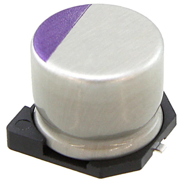
Marking : Polarity( ), Rated voltage, Lot.No.
(Purple) SVP(Upper E7), Rated capacitance.
F8
F8
F8,E12
F8,E12
F12
F12
F12
F12
F12
※For the minimum packing quantity, please refer to page 55.
30
(unit : mm)
Size Code
A5
B6
C6
E7
F8
E12
F12
a
1.0
1.4
2.1
2.8
4.3
2.8
4.3
b
6.2
7.4
9.1
11.1
13.1
11.1
13.1
c
1.6
1.6
1.6
1.9
1.9
1.9
1.9
�4. SPECIFICATIONS FOR EACH SERIES
■Table7 SVP Series Characteristics List
Size
Code
B6
C6
E7
F8
E12
F12
※1
※2
※3
16SVP3R3M
10SVP4R7M
10SVP6R8M
10SVP10M
10SVP15M
6SVP22M
4SVP33M
20SVP10M
16SVP15M
16SVP22M
10SVP33M
6SVP47M
4SVP39M
4SVP68M
25SVP6R8M
20SVP22M
20SVP27M
16SVP39M
10SVP47M
10SVP56M
6SVP82M
6SVP100M
6SVP120MV
4SVP150MX
2R5SVP220M
25SVP10M
20SVP33M
20SVP47M
16SVP56M
16SVP82M
10SVP120M
10SVP150MX
6SVP220MX
4SVP150M
4SVP330M
25SVP22M
20SVP56M
20SVP68M
16SVP100M
16SVP150M
16SVP180MX
10SVP150M
10SVP270M
10SVP330MX
6SVP220M
6SVP330M
6SVP470MX
4SVP680M
25SVP33M
20SVP100M
16SVP180M
10SVP330M
6SVP470M
4SVP560M
2R5SVP680M
25SVP56M
20SVP150M
16SVP330M
10SVP560M
6SVP820M
4SVP1200M
2R5SVP1500M
※3
※3
※3
※3
※3
16
10
10
10
10
6.3
4
20
16
16
10
6.3
4
4
25
20
20
16
10
10
6.3
6.3
6.3
4
2.5
25
20
20
16
16
10
10
6.3
4
4
25
20
20
16
16
16
10
10
10
6.3
6.3
6.3
4
25
20
16
10
6.3
4
2.5
25
20
16
10
6.3
4
2.5
Rated
Capacitance
(µF)
Rated
ESR
100kHz to 300kHz ripple current
(mΩ) (max.)
(mArms)
3.3
4.7
6.8
10
15
22
33
10
15
22
33
47
39
68
6.8
22
27
39
47
56
82
100
120
150
220
10
33
47
56
82
120
150
220
150
330
22
56
68
100
150
180
150
270
330
220
330
470
680
33
100
180
330
470
560
680
56
150
330
560
820
1200
1500
260
240
240
220
200
200
200
120
120
90
70
70
70
60
80
60
60
50
50
45
45
40
17
40
23
60
45
45
45
40
35
35
35
35
35
50
40
40
35
30
30
30
25
25
25
25
25
25
30
24
20
17
15
13
13
28
20
16
13
12
12
12
660
670
670
700
740
740
740
1020
1020
1060
1100
1100
1100
1400
1200
1450
1450
1620
1620
1700
1700
1810
2780
1810
2390
1500
1890
1890
1890
2120
2560
2560
2560
2560
2560
2000
2400
2400
2670
3020
3020
3020
3700
3700
3700
3700
3700
3700
2980
3320
3640
3950
4210
4520
4520
3800
4320
4720
5230
5440
5440
5440
Tangent of
loss angle
(max.)
0.07
0.08
0.09
0.10
0.10
0.12
0.15
0.10
0.10
0.10
0.12
0.12
0.12
0.12
0.10
0.10
0.10
0.10
0.12
0.12
0.12
0.12
0.12
0.12
0.12
0.10
0.12
0.12
0.12
0.12
0.12
0.12
0.12
0.12
0.12
0.10
0.12
0.12
0.12
0.12
0.12
0.12
0.12
0.12
0.12
0.12
0.12
0.12
0.12
0.15
0.15
0.15
0.15
0.15
0.15
0.12
0.15
0.15
0.15
0.15
0.18
0.18
Leakage
current (µA)
(max.)※2
26.4
23.5
34.0
50.0
75.0
69.3
66.0
100
120
176
165
148
78
136
85
88
108
125
94
112
103
126
151
120
110
125
132
188
179
262
240
300
277
120
264
275
224
272
320
480
576
300
540
660
277
416
592
544
413
400
576
660
592
448
340
700
600
792
840
775
960
750
Specifications for
each series
A5
Rated
Voltage
(V)
Part Number
※1
Capacitance tolerance : M ±20%
After 2 minutes
The surge voltage of 25V products is 25V. Please consider SVPD series 25V products (whose surge voltage is 29V)
in placing a new order.
Frequency coefficient for ripple current
Frequency
Coefficient
120Hz≦ f <1kHz
0.05
1kHz≦ f <10kHz
0.3
10kHz≦ f <100kHz
0.7
100kHz≦ f ≦500kHz
1
31
�
很抱歉,暂时无法提供与“20SVP33M”相匹配的价格&库存,您可以联系我们找货
免费人工找货- 国内价格 香港价格
- 1+14.760981+1.90172
- 10+9.5545610+1.23096
- 50+7.3877650+0.95180
- 100+6.70529100+0.86387
- 500+5.52865500+0.71228