This product complies with the RoHS Directive (EU 2002/95/EC).
Transistors
2SD0814A (2SD814A)
Silicon NPN epitaxial planar type
For high breakdown voltage low-frequency and low-noise
amplification
Unit: mm
0.40+0.10
–0.05
0.16+0.10
–0.06
Rating
Unit
VCBO
185
V
Collector-emitter voltage (Base open)
VCEO
185
V
Emitter-base voltage (Collector open)
VEBO
5
V
IC
ICP
Collector power dissipation
PC
Junction temperature
Tj
Storage temperature
Tstg
50
mA
100
mA
200
mW
150
°C
−55 to +150
°C
0.4±0.2
1.1+0.3
–0.1
Symbol
0 to 0.1
Parameter
1.1+0.2
–0.1
10˚
Collector-base voltage (Emitter open)
Peak collector current
5˚
di
p
Pl
lan nclu
ea
e
se
pla m d m des
ne ain ain foll
htt visit
d te t o
p:/ fo
/w llo dis disc nan enan wing
ww wi co on ce c fo
.se ng ntin tin ty e ty ur
mi UR ue ued pe pe Pro
co L a d t ty
du
n.p bo yp pe
ct
life
an ut e
d
as lat
cy
on es
cle
ic. t in
sta
co fo
ge
.jp rm
.
/en at
i
o
/
n.
1.9±0.1
2.90+0.20
–0.05
■ Absolute Maximum Ratings Ta = 25°C
Collector current
2
1
(0.95) (0.95)
(0.65)
• High collector-emitter voltage (Base open) VCEO
• Low noise voltage NV
• Mini type package, allowing downsizing of the equipment and
automatic insertion through the tape packing and the magazine
packing.
2.8+0.2
–0.3
■ Features
1.50+0.25
–0.05
M
Di ain
sc te
on na
tin nc
ue e/
d
3
1: Base
2: Emitter
3: Collector
EIAJ: SC-59
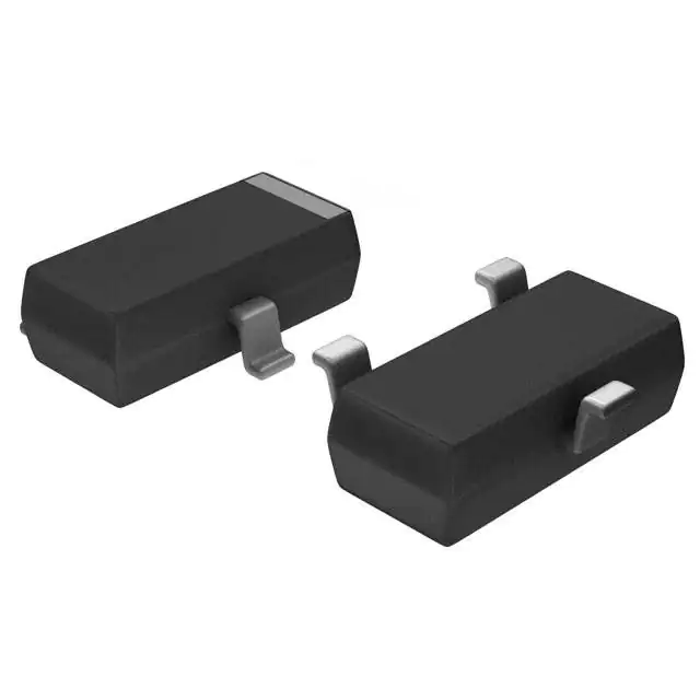
Mini3-G1 Package
Marking Symbol: L
ue
■ Electrical Characteristics Ta = 25°C ± 3°C
Symbol
ce
/D
isc
on
tin
Parameter
Conditions
Min
Collector-emitter voltage (Base open)
VCEO
IC = 100 µA, IB = 0
185
Emitter-base voltage (Collector open)
VEBO
IE = 10 µA, IC = 0
5
Collector-base cutoff current (Emitter open)
ICBO
VCB = 100 V, IE = 0
hFE
VCE = 5 V, IC = 10 mA
VCE(sat)
IC = 30 mA, IB = 3 mA
an
Forward current transfer ratio *
en
Collector-emitter saturation voltage
Typ
Max
Unit
V
V
90
1
µA
330
1
V
VCB = 10 V, IE = −10 mA, f = 200 MHz
150
MHz
Collector output capacitance
(Common base, input open circuited)
Cob
VCB = 10 V, IE = 0, f = 1 MHz
2.3
pF
Noise voltage
NV
VCE = 10 V, IC = 1 mA, GV = 80 dB
Rg = 100 kΩ, Function = FLAT
150
mV
fT
Ma
int
Transition frequency
Note) 1. Measuring methods are based on JAPANESE INDUSTRIAL STANDARD JIS C 7030 measuring methods for transistors.
2. *: Rank classification
Rank
Q
R
S
hFE
90 to 155
130 to 220
185 to 330
Note) The part number in the parenthesis shows conventional part number.
Publication date: January 2003
SJC00196CED
1
�This product complies with the RoHS Directive (EU 2002/95/EC).
2SD0814A
PC Ta
IC VCE
Ta = 25°C
100
Collector current IC (mA)
200
160
100
IB = 2.0 mA
1.8 mA
1.6 mA
1.4 mA
1.2 mA
1.0 mA
0.8 mA
0.6 mA
80
60
VCE = 10 V
25°C
0.4 mA
Ta = 75°C
80
80
120
160
1
Ta = 75°C
−25°C
0.01
0.1
1
10
100
Cob VCB
en
an
IE = 0
f = 1 MHz
Ta = 25°C
Ma
int
4
3
6
8
2
1
3
10
400
Ta = 75°C
300
25°C
−25°C
200
100
0
0.1
1
10
Collector current IC (mA)
30
100
Collector-base voltage VCB (V)
2
12
0
SJC00196CED
100
0.4
0.8
1.2
1.6
2.0
Base-emitter voltage VBE (V)
fT I E
200
VCE = 10 V
1
0
10
500
ce
/D
isc
on
tin
Collector current IC (mA)
5
4
600
Forward current transfer ratio hFE
Collector-emitter saturation voltage VCE(sat) (V)
10
0.1
2
hFE IC
IC / IB = 10
25°C
0
0
Collector-emitter voltage VCE (V)
VCE(sat) IC
100
0
Transition frequency fT (MHz)
80
di
p
Pl
lan nclu
ea
e
se
pla m d m des
ne ain ain foll
htt visit
d te t o
p:/ fo
/w llo dis disc nan enan wing
ww wi co on ce c fo
.se ng ntin tin ty e ty ur
mi UR ue ued pe pe Pro
co L a d t ty
du
n.p bo yp pe
ct
life
an ut e
d
as lat
cy
on es
cle
ic. t in
sta
co fo
ge
.jp rm
.
/en at
i
o
/
n.
40
40
20
ue
0
Ambient temperature Ta (°C)
Collector output capacitance
C (pF)
(Common base, input open circuited) ob
0.2 mA
20
40
0
40
−25°C
60
M
Di ain
sc te
on na
tin nc
ue e/
d
120
120
Collector current IC (mA)
Collector power dissipation PC (mW)
IC VBE
120
240
VCB = 10 V
Ta = 25°C
160
120
80
40
0
−1
−10
Emitter current IE (mA)
−100
�Request for your special attention and precautions in using the technical information and
semiconductors described in this book
(1) If any of the products or technical information described in this book is to be exported or provided to non-residents, the laws and
regulations of the exporting country, especially, those with regard to security export control, must be observed.
(2) The technical information described in this book is intended only to show the main characteristics and application circuit examples
of the products, and no license is granted under any intellectual property right or other right owned by our company or any other
company. Therefore, no responsibility is assumed by our company as to the infringement upon any such right owned by any other
company which may arise as a result of the use of technical information described in this book.
M
Di ain
sc te
on na
tin nc
ue e/
d
(3) The products described in this book are intended to be used for standard applications or general electronic equipment (such as office
equipment, communications equipment, measuring instruments and household appliances).
Consult our sales staff in advance for information on the following applications:
– Special applications (such as for airplanes, aerospace, automobiles, traffic control equipment, combustion equipment, life support
systems and safety devices) in which exceptional quality and reliability are required, or if the failure or malfunction of the products may directly jeopardize life or harm the human body.
– Any applications other than the standard applications intended.
d
pla inc
ne lud
se
pla m d m es
v
ne ain ain foll
htt isit
d te t o
p:/ fo
/w llo dis disc nan enan wing
ww wi co on ce c fo
.se ng ntin tin ty e ty ur
mi UR ue ued pe pe Pro
co L a d t ty
du
n.p bo yp pe
ct
life
an ut e
d
as lat
cy
on es
cle
ic. t in
sta
co fo
ge
.jp rm
.
/en at
i
o
/
n.
(4) The products and product specifications described in this book are subject to change without notice for modification and/or improvement. At the final stage of your design, purchasing, or use of the products, therefore, ask for the most up-to-date Product
Standards in advance to make sure that the latest specifications satisfy your requirements.
(5) When designing your equipment, comply with the range of absolute maximum rating and the guaranteed operating conditions
(operating power supply voltage and operating environment etc.). Especially, please be careful not to exceed the range of absolute
maximum rating on the transient state, such as power-on, power-off and mode-switching. Otherwise, we will not be liable for any
defect which may arise later in your equipment.
Even when the products are used within the guaranteed values, take into the consideration of incidence of break down and failure
mode, possible to occur to semiconductor products. Measures on the systems such as redundant design, arresting the spread of fire
or preventing glitch are recommended in order to prevent physical injury, fire, social damages, for example, by using the products.
(6) Comply with the instructions for use in order to prevent breakdown and characteristics change due to external factors (ESD, EOS,
thermal stress and mechanical stress) at the time of handling, mounting or at customer's process. When using products for which
damp-proof packing is required, satisfy the conditions, such as shelf life and the elapsed time since first opening the packages.
Pl
ea
Ma
int
en
an
ce
/D
isc
on
tin
ue
(7) This book may be not reprinted or reproduced whether wholly or partially, without the prior written permission of Matsushita
Electric Industrial Co., Ltd.
�