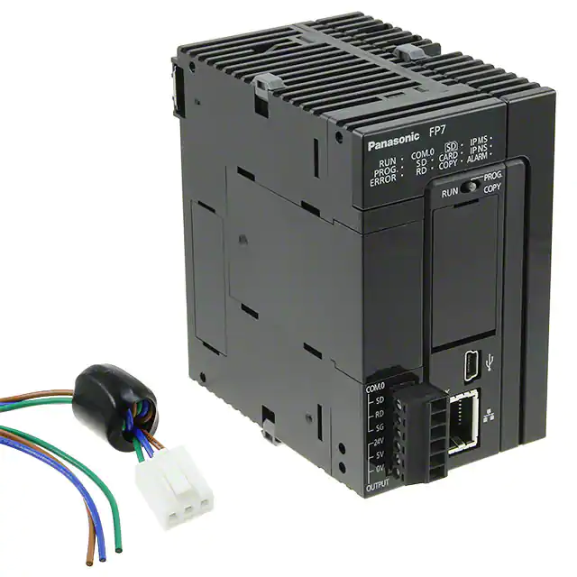
Programmable Controller
FP7 SERIES
Conforming to
EMC Directive
(except AFPRP2□)
Listing
(except some models)
Automation Controls + Information
Panasonic PLCs also control information
2015.10
panasonic.net/id/pidsx/global
�Do more than just control machinery.
Automation Controls
Move
Collect
02
FP7 SERIES
Store
�Continually evolving FP7
+ Information
Transfer
Cloud
Check
Single PLC with two roles
Enter an era in which you can see the “current state” of the remote site.
FP7 SERIES
03
�Automation Controls
Move
Control machinery and facilities
Along with operation speed and capacity,
delivers ease of use for design, production,
and maintenance.
EtherNet/IP compatibility
Models with built-in Ethernet ports add functionality to CPU unit.
Easy connection with all kinds of robots and PLCs enables control and
communication.
*EtherNet/IP is a trademark of ODVA, Inc.
Cassette system
reduces unit cost and footprint
With ease and at low cost, extend the serial communication and analog
functionality of CPU units.
Serial communication cassettes
● RS232C
● RS422
●2
/ RS485
channels
Function cassettes
● Analog
Cylinder,
Slider and
Remote I/O, etc.
input
input and output
● Thermocouple input
● Analog
PLC of each
company
HUB
Ethernet communication cassette
*Ethernet is a registered
trademark of Fuji Xerox Co.,
Ltd. and Xerox Corporation.
• AFP7CPS41E(S)
• AFP7CPS31E(S)
Server
TCP / IP
No communication
unit
PC
Moreover, when used as a serial communication unit, expansion to as
many as 35 channels is possible. Reduces cost and footprint.
4 channels
CPU
unit
Supports max. 8 units and 32 ports!!
High cost performance model CPU unit
End
unit
Analog input unit
Ideal for Simple Standalone Systems
Analog sampling that doesn’t depend on CPU
Achieve high-performance extensibility, lower cost and slimmer form
factor.
34 mm
Sampling and data collection in the analog unit!
Ideal for high-accuracy measurement applications because with the
fixed cycle, analog signal can be held in the buffer
1.339 in
High cost performance model FP7 CPU unit
AFP7CPS21
Saves space and reduces cost
Another FP7 advantage:
add-on cassette system
reduces unit cost and footprint.
Function cassettes
• Analog input
• Analog input and output
• Thermocouple input
Communication cassettes
• Serial
• Ethernet
16 intelligent units can be mounted
Low in cost, 16 intelligent units can be mounted.
Dependent on scan of CPU
The scan gets delayed when the CPU
slows down due to other processes and
sampling becomes sporadic
Occurrence of failure
Sampling in the analog unit
Accurate sampling possible with
fixed cycle.
• Doesn’t depend on CPU scanning
• Analog buffering
• High-speed conversion: 25 μs/ch
• Overall accuracy: ± 0.05 % F.S.
(at +25 °C +77 °F)
Up to 16 units can be mounted!
04
FP7 SERIES
�Continually evolving FP7
+ Information
Collect
Equipped to deal with any protocol, it can be
installed in existing facilities to enable
collection of information.
Communication method
● EtherNet/IP
● MC
protocol
(RTU and TCP)
Collect work site information
The FP7 can collect voltage, electric power,
temperature, production output, alarm
notifications, and other information.
Communicating with up to 220 equipment units
Communicate easily with many units,
including automation control
equipment such as PLCs and
information equipment such as PCs.
● Modbus
Connection to
information
equipment:
4 units
FP7
Existing
PLC
Collect
Existing
facilities
To enable information collection, because the FP7 can
deal with any protocol for Ethernet / serial
communications, the FP7 can be installed in existing
facilities.
Store
Easy multiple concurrent logging
Logging set up is done via the configuration screen.
Moreover, it is possible to keep up to 16 files concurrently active.
Ethernet-compatible equipment
PLC
Connection to automation control equipment:
216 units (Simultaneous connection: 16 units)
Logs collected information
The FP7 securely stores and carries out
log management of collected information
assets.
Use program and data register sharing to
resolve data space shortage.
No need repurchase expensive upgrade models.
Example: 196 k steps type CPU unit AFP7CPS41E(S)
Initial state
Program:
196 k steps
• Various triggers:
periodic, cycle, bit,
startup, etc.
Data register:
256 k words
Data-driven setting Program-driven setting
Program:
145 k steps
Program:
221 k steps
Data register:
512 k words
Data register:
128 k words
E.g. for large amount E.g. for large amount
of log data
of operation programs
Protection of log data
Diagnosis of rewrite life of SD memory card helps
protect valuable information assets.
*Diagnosis possible when Panasonic industrial-spec SD memory cards are used.
Reference value: for 196 k steps type CPU unit (Note)
Program
234 k
steps
221 k
steps
196 k
steps
145 k
steps
52 k
steps
Data
register
64 k
words
128 k
words
256 k
words
512 k
words
976 k
words
Note: For data register (DT), data up to 256 k words can be backed up.
FP7 SERIES
05
�+ Information
Transfer
Information can be transferred
to different types of media
FP7 transmits information to PC, server
or the cloud, etc.
Cloud
Information can be transferred to different types of media
HTTP(S) client function (SSL-compatible)
Allows the PC to read the logging data in the FP7’s SD memory card
and to write setting values and other parameters.
Transfer data from the FP7 to a web server for easy viewing with a
browser. Send and receive data from multiple FP7 units on a schedule
controlled by the FP7.
Communicate both inside the firewall on an intranet and outside the
firewall to the wider world through the Internet.
Read from FP7
Data
file
Corporate LAN
External LAN (Internet)
Write to FP7
Manage your records by summarizing
measurement data from your sensors together with
result information from the inspection machines.
SD memory
card
logging
CPU unit + Analog unit only
Encoder trigger
Analog
Ethernet
HL-G1
Motor control
Monitoring Web server
the operation
of multiple
units with a
browser
Web server
The FP7 can
communicate through
a firewall to an external
server
Monitoring
the operation
of multiple
units with a
browser
Allow users from around the world to access the current
state of their equipment.
Data transfer to company server
Text
PC +
Spreadsheet software, etc.
FTP(S) client function (SSL-compatible)
The FP7 can generate and write data files to an FTP server on a PC
as well as read data files from the FTP server.
The sessions use SSL, protecting IDs and passwords.
Write to PC (server)
Data collection,
data viewing and
Data
data writing from
file
multiple units in
the form of files
Read from PC (server)
Transfer electric power data from factories and
offices to an FTP server on a regular basis.
PC (FTP server)
Users can access the accumulating
production information in the
server at any time.
FTP server
Product A: 300 pieces / 400 pieces
Product B: 230 pieces / 300 pieces
06
FP7 SERIES
FP7
Web
server
FP7 value-setting display
Data transfer to cloud server
Cloud
FP7
Web
server
FP7 value-setting display
�Continually evolving FP7
+ Information
Check
Check information at your fingertips
Data collected by the FP7 can be displayed in a web browser.
Via smartphone or PC, it’s easy to check the current
state of the work site.
Web server function
Information updates viewable in e-mail.
Monitor and control the FP7 without the use of custom software. Users
can check the accumulated data in the FP7 with a browser.
The managers can receive and view e-mailed malfunction notifications
and daily reports of equipment operations.
Operation can be
monitored with a
browser and control
instructions can be
sent from a browser.
Data
E-mail sending function (SSL-compatible)
Use instructions and timings controlled by the FP7 to send e-mails on a
pre-set schedule or when a pre-set condition changes in the PLC. The
e-mails can have data files attached and communication is
SSL-capable to protect the e-mails.
1. Check out status of greenhouse / food
processing
E-mail
With data always at hand, there’s no need to go to the
work site to check indoor temperature and humidity or
the operation of pumps, heaters, and other equipment.
Receive monitoring e-mails.
Receive emergency e-mails.
Send the results and a notice of completion
when a long-term test is completed.
E-mail
2. Operational status and production log
management for production line
Operational status of the production line can be checked
and traceability production control can be carried out.
Current production line information can be collected and
displayed on Web interface.
PLC of other company
FP7
The long-term test (30-day) has been
completed.
Average temperature: ○○ °C
Duration time: ○○ hours
Number of test cycles: ○○ times
Receive a daily e-mail on your smartphone with
the amount of electric power generated.
E-mail
MC protocol* *QnA compatibility: 3E frame binary
Modbus (TCP) Batch read / write
Master / slave communication
EtherNet/IP
3. Building lighting / entry and exit management
Through a web interface, it is possible to check the status
of lighting in buildings and apartments, and to building
entries and exits.
Receive at 6 PM every day
Amount of today's electric
power generation: 430 kWh
For more information on
web server function,
please see this catalog.
FP7 SERIES
07
�Maintenance
Historical archiving of program
changes
Operational events to CPU and program editing events
are logged. Useful for debugging and tracing the cause
of malfunctions
The built-in program backup allows
users to immediately recover factory
default conditions.
The CPU unit can store two programs. In the event of
fault, no SD memory card is needed to return to a
previously saved backup program.
Execution program
Date of occurrence
Time
Trigger
Program
2014/11/21
14:05:35
Power: ON
2014/11/21
14:07:13
Open cover
2014/11/21
14:20:25
Insert SD memory card.
2014/11/21
14:30:19
Close cover
2014/11/21
14:31:00
Download program
2014/11/21
14:33:10
Switch operation mode to RUN
2014/11/21
14:35:12
Program edition during RUN
2014/11/21
14:35:32
Upload program
2014/11/21
14:40:07
Power: OFF
Set a maintenance schedule that is
based on an automatic measurement
of contact switching cycles or overall
ON time.
Service intervals can be timed according to logged
contact switching cycles, and power-on duration, thus
enabling preventive maintenance of equipment and
peripheral equipment.
T = T1 + T2 + T3
Number of ON
operations of
contact
T1
1 time
T2
2 times
T3
3 times
Records the PLC's ON time
Equipment operating time can be estimated. You can decide
which equipment to give priority to reactivate if more than one
item of equipment is idle.
08
FP7 SERIES
Execution
program 1
Execution
program 2
Improvement
Program
Execution
program 3
Improvement
Program
Execution
program 4
Malfunction!
Program
Program
No need to replace a battery by data
back up function without battery.
Equipment maintenance tasks are reduced because
battery is not required. And, to save power, equipment
can be switched off without hesitation.
Battery
Automatically measures and logs total ON times and
number of ON operations of connected sensors.
Output contacts (Y): Automatically measures and logs total ON times and
number of ON operations of connected actuators. The
maintenance schedules for relays, motors, etc. can be
optimized.
Contact
ON time
Load previously
saved backup
program to restore
a fall-back version
Backup
*Data logs are virtual.
Input contacts (X):
Backup program
Two
program
areas
Without battery
With battery
Program holding
Item
Yes
Yes
Data register holding (Note 1)
Yes
Yes
Clock / calendar operation
No (Note 2)
Yes
Notes: 1) Data register (DT) of up to 256 k words can be backed up.
2) Clock / calendar operation can be held for about a week if the
equipment is switched off. (Allow at least 30 minutes of
equipment ON time.)
The built-in clock / calendar function can be adjusted via
Ethernet. Adjustment at power start up allows the battery-free
system to be configured.
�Continually evolving FP7
Security and Compact design
Program level encryption ensures
protection against copying program code.
A high performance PLC with a small
footprint.
Security enhanced type
• Programs cannot be decrypted.
• Even if the program is copied, it
will not operate.
Encrypted program
Program
Program
Decryption key
[ Decryption key ]
Activation is possible only if the decryption key on the FP7 matches
that of the program. (Copied programs will not be activated on other
FP7.)
Copy
90 mm
3.543 in
Insertion
Program
Original FP7
Copied program
Other FP7
Any attempt to copy the installed equipment’s program into a
newly purchased FP7 will fail due to an unmatched decryption
key, resulting in the equipment becoming inoperable.
*When exporting to China, please use a CPU that does not have an
encryption function.
Space saving
83 3.268
mm
in
Without the requirement of a power supply
unit or backplane, you can reduce the cost
and footprint of your PLC configuration.
No power supply unit
No backplane
A 24 V DC power can be directly
connected from the control panel.
*Add a power supply unit if AC power
is required.
Power supply unit cannot be used
with AFP7CPS21 CPU uint.
FP7 SERIES
09
�FP7 series Lineup
CPU units
P.12
Standard model
AFP7CPS41E
AFP7CPS31E
AFP7CPS21
AFP7CPS31
End unit
Standard model
Security
enhanced type
AFP7CPS41ES
AFP7CPS31ES
Expansion
units
P.13
Expansion
master unit
AFP7EXPM
Expansion
slave unit
AFP7EXPS
AFP7END
*Included with CPU
unit and Expansion
slave unit
AFP7CPS31S
Power
supply
units
P.26
AC power supply units
AC power
supply unit
AFP7PSA1
AC power supply unit
(High-capacity type)
AFP7PSA2
Add-on
cassettes
P.14 and 15
Communication cassettes
RS232C
1 channel
AFP7CCS1
RS232C
2 channels
AFP7CCS2
RS422 / RS485
1 channel
AFP7CCM1
Ethernet
1 channel
AFP7CCET1
Function cassettes
Digital input
and output
units
Analog input
and output
AFP7FCA21
Serial
communication
unit
Thermocouple input
AFP7FCTC2
Input units
Terminal block
16 points, 12 to 24 V
DC input
AFP7X16DW
MIL connector
32 points, 24 V
DC input
AFP7X32D2
MIL connector
64 points, 24 V
DC input
AFP7X64D2
Output units
Terminal block
16 points,
relay output
AFP7Y16R
Terminal block
16 points,
transistor output
(sink)
AFP7Y16T
MIL connector
32 points,
transistor output
(sink)
AFP7Y32T
Terminal block
16 points,
transistor output
(source)
AFP7Y16P
MIL connector
32 points,
transistor output
(source)
AFP7Y32P
MIL connector
64 points,
transistor output
(source)
AFP7Y64P
P.16 to 18
Input and output
units
10
Analog input
AFP7FCAD2
FP7 SERIES
MIL connector
32 points, 24 V DC input
32 points, transistor output
(sink)
AFP7XY64D2T
RS422 / RS485
2 channels
AFP7CCM2
MIL connector
32 points, 24 V DC input
32 points, transistor output
(source)
AFP7XY64D2P
P.26
RS232C 1 channel
and RS485 1 channel
AFP7CCS1M1
AFP7NSC
*Communication
cassette is sold
separately
*Dedicated serial
communication
MIL connector
64 points,
transistor output
(sink)
AFP7Y64T
Terminal
block
AFP7TER
*included with I/O
unit and Analog I/O
unit with terminal
block
�Pr o g r a mma b le
c o n tr o l l e r
Analog input
and output
units
Input units
Analog input unit
High-speed and
high-accuracy type
4 points, voltage and
current
AFP7AD4H
Output unit
Analog output unit
High-speed and
high-accuracy type
4 points, voltage and
current
AFP7DA4H
P.19
High-speed
counter
units
P.21
Positioning
units
P.22
Pulse train
Pulse
output
units
P.23
Analog input unit
High-speed and
multi-channel type
8 points, voltage and current
AFP7AD8
FP7 SERIES
Temperature
input units
Thermocouple multiple analog input unit
Thermocouple
input and
analog input
AFP7TC8
Resistance temperature detector input unit
Resistance
temperature
detector input
AFP7RTD8
P.20
2 channels
16 MHz (for 2-phase,
4-multiple)
4 MHz (for individual
input)
AFP7HSC2T
4 channels
16 MHz (for 2-phase, 4-multiple)
4 MHz (for individual input)
AFP7HSC4T
Transistor output
2 axes
500 kpps
AFP7PP02T
Transistor output
4 axes
500 kpps
AFP7PP04T
Line driver output
2 axes
4 Mpps
AFP7PP02L
Line driver output
4 axes
4 Mpps
AFP7PP04L
Transistor output
2 axes
500 kpps
AFP7PG02T
Transistor output
4 axes
500 kpps
AFP7PG04T
Line driver output
2 axes
4 Mpps
AFP7PG02L
Line driver output
4 axes
4 Mpps
AFP7PG04L
PHLS
(remote I/O)
units
P.24 and 25
PHLS master unit
AFP7PHLSM
PHLS slave units
Input type
Compact type
(e-CON)
8 points, 24 V DC input
AFPRP2X08D2E
PHLS slave units
Output type
Compact type
(Connector-type terminal block)
16 points, transistor output (sink)
AFPRP2Y16T
PHLS slave units
Input and output types
Compact type
(Connector-type terminal block)
8 points, 24 V DC input
8 points, transistor output (sink)
AFPRP2XY16D2T
Compact type
(Connector-type
terminal block)
16 points, 24 V DC input
AFPRP2X16D2
Standard type
(Screw-type
terminal block)
8 points, 24 V DC input
AFPRP1X08D2
Compact type
(Connector-type terminal block)
4 points, relay output
AFPRP2Y04R
Standard type
(Screw-type
terminal block)
16 points, 24 V DC input
AFPRP1X16D2
Standard type
(Screw-type terminal block)
16 points, transistor output (sink)
AFPRP1Y16T
Standard type
(Screw-type terminal block)
8 points, 24 V DC input
8 points, transistor output (sink)
AFPRP1XY16D2T
FP7 SERIES
11
�CPU units
Basic performance [For AFP7CPS41E(S)]
• Operation speed:
• Program capacity:
• Data registers:
• Number of unit connection:
Min. 11 ns/step
196 k steps
256 k words
Max. 16 units
Compact design and class-leading high performance
1. The function is expanded easily with cassette interface.
The function extension is possible without increasing the width of the unit.
The cassettes support RS232C, RS422 and RS485 for series communication,
Ethernet communication and various analog input and output.
2. High-capacity SD (SDHC) memory cards of up to 32 GB
are supported.
Enables large storage for log data *except for AFP7CPS21
3. High performance (min. scan time 1ms, max. 20 μs for
60 k steps)
The processing speed is less susceptible to frequent Ethernet communication
AFP7CPS41E(S)
AFP7CPS31E(S)
AFP7CPS31(S)
4. All communications ports are safely isolated
AFP7CPS21
End unit
(attached to the
each CPU unit)
Confidently use any port - RS422 / RS485 and LAN ports, as well
as USB and RS232C ports - each is isolated.
5. High function types, increased security (encryption),
are available.
*When exporting to China, please use a CPU that does not have an encryption function.
■ Control specifications
Item
Memory selection pattern (Note 1)
Memory Program (steps) (Note 2)
capacity Data register (words) (Note 2)
Number of max. program block (PB)
1
234,000
65,536
468
■ COM port communication specifications
AFP7CPS41E(S) (Note 6)
2
3 (Factory default)
4
221,500 196,000 144,500
131,072 262,144 524,288
443
392
289
5
51,500
999,424
103
Item
AFP7CPS31E(S) / AFP7CPS31(S) (Note 6)
Memory selection pattern (Note 1) 1 (Factory default)
2
3
4
121,500
96,000
64,000
32,000
Memory Program (steps) (Note 2)
(Note
2)
capacity Data register (words)
131,072
262,144
425,984
589,824
Number of max. program block (PB)
243
192
128
64
Item
Memory selection pattern (Note 1)
Memory Program (steps) (Note 2)
capacity Data register (words) (Note 2)
Number of max. program block (PB)
AFP7CPS21
1 (Factory default)
64,000
131,072
128
2
32,000
262,144
64
AFP7CPS41E(S) / AFP7CPS31E(S) / AFP7CPS31(S) / AFP7CPS21
Relay symbol method
Cyclic operation method
Built-in flash ROM (no backup battery required)
Basic instruction: Min. 11 ns/step (AFP7CPS21: 14 ns/step)
8,192 points (Note 4) / 8,192 points (Note 4)
32,768 points
Indicate operation status of various relays is shown.
16,384 points
4,096 points: Timer capable of counting (units: 10 μs,
Timers (T)
1 ms, 10 ms, 100 ms or 1 sec.) × 4,294,967,295
1,024 points, Counter capable of counting 1 to 4,294,967,295
Counters (C)
Link data registers (LD)
16,384 words
System data registers (SD) Internal operation status of various registers is shown.
Index registers (I0 to IE)
15 long words / With switching function
Master control relay (MCR) Unlimited
Number of labels (LOOP)
Max. 65,535 points for each program block (PB)
Differential points
Unlimited
Number of step ladders
Unlimited
Number of subroutines
Max. 65,535 points for each program block (PB)
Number of interrupt programs 1 periodical interrupt program
SD memory card function
SDHC memory cards of up to 32 GB are usable. *except for AFP7CPS21
Constant scan
Available (0 to 125 ms)
Real time clock (Note 3)
Built in. Date backup with battery.
3.3 years or more (at 25 °C 77 °F) (when no power is
Battery life
supplied) *except for AFP7CPS21
Password / Restricted distribution / Read disable setting / Encryption
Security function (Note 5)
Max. 16 units, link relays: 1,024 points, link registers: 128 words.
PLC link function
(Data transfer and remote programming are not supported)
(Link area allocation is switchable between the first and the second half)
Item
Programming method
Control method
Program memory
Operation speed
External input (X) / output (Y)
Internal relays (R)
System relays (SR)
Link relays (L)
Notes: 1) The factory default setting is pattern 3 for AFP7CPS41E(S) and pattern 1 for
AFP7CPS31E(S), AFP7CPS31(S) and AFP7CPS21.
2) For data register (DT), data up to 262,144 words can be backed up.
3) Precision of calendar; At 0 °C 32 °F, less than 95 seconds error per month, At 25 °C 77 °F,
less than 15 seconds error per month, At 55 °C 131 °F, less than 130 seconds error per
month
4) Hardware configuration governs the actually usable number of I/O points. When I/O
points are not actually used, usable as internal relays.
5) Encryption can be used for AFP7CPS41ES, AFP7CPS31ES and AFP7CPS31S.
6) Products with an “S” at the end of a part number have the encryption function.
12
FP7 SERIES
Item
Interface
Transmission distance
Transmission speed
Communication method /
Synchronous method
Transmission format
Data transmission order
Communication mode
Specifications
RS232C, three-wire system, 1 channel (Note 1)
15 m 49 ft
300, 600, 1200, 2400, 4800, 9600, 19200,
38400, 57600, 115200, 230400 bits/sec.
Half-duplex system / Start-stop synchronization
system
Stop bit: 1 bit / 2 bits
Parity: none / odd / even
Data length: 7 bits / 8 bits
Start code: with STX / without STX
End code: CR / CR + LF / none / ETX
Transmit from bit 0 in character units.
General-purpose communication, Computer link and MODBUS-RTU
Note: 1) SD, RD and SG terminals are isolated from internal circuits.
■ Dedicated power supply output port specifications for GT series programmable display
Output terminal (Note 1)
5V
24 V (Note 2)
Connecting programmable display model
For 5 V DC type GT series Programmable Display
For 24 V DC type GT series Programmable Display
Notes: 1) 5 V and 24 V DC types are not usable at the same time.
2) Use 21.6 to 26.4 V DC to power the CPU unit.
Please check the “GT Series Manual” for grounding of the GT series programmable
display.
The AFP7CPS21 is not provided with this port.
■ LAN port communication specifications [except for AFP7CPS31(S) / AFP7CPS21]
Item
Communication interface
Baud rate
Total cable length
Number of nodes
Number of simultaneous connections
Communication protocol
(Communication layer)
DNS
DHCP / DHCPV6
FTP server /
Client (SSL compatible)
Specifications
Ethernet 100BASE-TX / 10BASE-T
100 Mbps, 10 Mbps auto negotiation function
100 m 328 ft (500 m 1,640 ft when a repeater is used)
Max. 254 units
Max. 220 connections (user connection: 216, system connection: 4)
TCP / IP, UDP
Supports name servers
Automatic IP address acquisition
Server function, file transfer, number of user: 3
Client function, data and file transfer
Server function, system web,
HTTP server /
Customer web (8 MB), number of concurrent session: 16
Client (SSL compatible)
Client function, data transfer
SMTP client (SSL compatible) Client function, mail transfer
SNTP
Time adjustment function
General-purpose communication 16 kB / 1 connection (user connection: 1 to 16)
Slave communication (MEWTOCOL-COM, MEWTOCOL7-COM,
MEWTOCOL-DAT, MODBUS-TCP, MC
Dedicated communication
protocol (Note 1))
Master communication (MEWTOCOL-COM, MEWTOCOL-DAT,
MODBUS-TCP, MC protocol (Note 1))
Note: 1) MC protocol is a short form denoting MELSEC communication protocol; MELSEC is a
registered trademark of Mitsubishi Electric Corporation.
QnA compatible 3E frame, only binary (bulk writing and bulk reading) use is available.
�Programmable
controller
Expansion units
FP7SERIES
Connect a maximum of 3 blocks and a total of 64 units
Three blocks can be expanded on one CPU unit. Distributed
installation achieved while maintaining high-speed bus transmission.
CPU
unit
Expansion master unit
Previous
Maximum of 16 units for each unit
Total
64 units
Expansion cable
Max. 16 units
Max.
3 blocks
Max. 16 units
Expansion slave units
AFP7EXPM
AFP7EXPS
End unit
(attached to the
AFP7EXPS)
Max. 16 units
■ Specifications
Product name
Item
Part No.
Number of
expansion
Block
Transmission
distance
Distance between blocks
Total extension
Max. allowable current
Expansion bus connector
Accessories
Expansion slave unit
AFP7EXPM
AFP7EXPS
Max. 3 blocks (total 4 blocks)
Unit
Current consumption (Note 2)
Net weight
Expansion master unit
Max. 48 units (total 64 units)
Length of expansion cable (0.5 m 1.640 ft, 1 m 3.281 ft, 3 m 9.843 ft and 10 m 32.808 ft)
Max. 30 m 98.425 ft (Expansion cable × 3 expansions) (Note 1)
120 mA or less
100 mA or less
–
3.0 A (at 24 V DC power supply terminal)
MIL 40 pins
MIL 40 pins × 2
120 g approx.
200 g approx. (including end unit)
–
Power supply cable (Part No.: AFPG805)
End unit (Part No.: AFP7END)
Notes: 1) Can support a maximum of 100 m 328 ft length between blocks. Please inquire with us for details.
2) Differs depending on power supply voltage and number of expansion units.
3) You cannot use the expansion units with the AFP7CPS21 CPU unit.
FP7 SERIES
13
�Add-on cassettes (communication cassettes)
For communication with programmable displays
or PCs and for data exchange between PLCs
1. Serial communication and Ethernet communication can
be added to the CPU.
6 types are available including cassettes that support any combination of
RS232C, RS485 and Ethernet.
AFP7CCM2
[Configuration example]
AFP7CCS1M1 AFP7CCET1
Network 1
Network 2
LAN1
LAN2
AFP7CCS1
AFP7CCS2
Global IP address
AFP7CCM1
Local IP address
(100BASE-TX, 10BASE-T)
2. Protocol supports MODBUS-RTU.
Communication can easily be accomplished using comfortable
communication instructions.
■Specifications
Interface
Item
Transmission distance
Transmission speed
Communication method
Synchronous method
Transmission format
Data transmission order
Max. number of stations
(Note 2, 3 and 4)
AFP7CCS1M1
AFP7CCS1
AFP7CCS2 (Note 7)
AFP7CCM1 (Note 6)
AFP7CCM2 (Note 6)
RS232C, 1 channel RS232C, 2 channels RS422 or RS485, 1 channel RS422 or RS485, 2 channels
RS232C, 1 channel and RS485, 1 channel
(Note 3 and 4)
Max. 1,200 m 3,937 ft at RS485 mode
Max. 15 m 49 ft
Max. 1,200 m 3,937 ft
Max. 15 m 49 ft (Note 2)
Max. 400 m 1,312 ft at RS422 mode (Note 3 and 4)
(RS232C) (Note 2)
(RS485) (Note 3 and 4)
300, 600, 1200, 2400, 4800, 9600, 19200, 38400, 57600, 115200, 230400 bits/sec.
Half-duplex
Start-stop synchronization
Stop bit: 1 bit / 2 bits
Parity: none / odd / even
Data length: 7 bits / 8 bits
Start code: with STX / without STX
End code: CR / CR + LF / none / ETX
Transmit from bit 0 in character units.
For program controlled
For program controlled communication:
communication: max. 99
max. 99 (Note 8)
(Note 8)
For computer link: max. 99
For computer link: max. 99
−
−
−
(Note 8)
For PLC link: max. 16
For PLC link: max. 16
For MODBUS-RTU: max. 99 (Note 8)
For MODBUS-RTU: max. 99
Notes: 1) When connecting a commercially available device that has an RS485 / RS422 interface, please confirm operation using the actual device.
In some cases, the number of station units, transmission distance and communication speed vary depending on the connected device.
2) Cable length should be no longer than 3 m 9.8 ft if communicating at a rate of 38.4 kbits/sec. or higher.
If you are using RS232C wiring, shielded cable should be used to improve noise immunity.
3) For RS485 setting, the values for transmission distance, transmission speed and number of connected units should be within the values noted in the graph below.
Maximum number of stations in RS485 communications
Number of stations
Baud rate: 230.4 kbps
Baud rate: 115.2 kbps
Baud rate: 57.6 kbps
99
70
40
20
0
200
656
700
1,000 1,200 (m ft)
2,297
3,281 3,937
Transmission distance
Item
Interface
Communication speed
Total cable length
Number of nodes
Number of simultaneous connections
Communication protocol (Communication layer)
DHCP
General-purpose communication
Dedicated communication
When using a transmission speed of 38.4
kbits/sec. or less, you can set up a maximum
of 1,200 m 3,937 ft and 99 units.
For RS422 setting, you can set up a maximum
transmission distance of 400 m 1,312 ft.
AFP7CCET1
Ethernet 100BASE-TX / 10BASE-TX
100 Mbps, 10 Mbps Auto negotiation function
100 m 328 ft (500 m 1,640 ft when a repeater is used)
Max. 254 units
Max. 4 connections (User connection: 3, System connection: 1)
TCP / IP, UDP
Automatic IP address acquisition
4 kB / 1 connection
Slave communication (MEWTOCOL-COM, MEWTOCOL7-COM, MEWTOCOL-DAT)
Master communication (MEWTOCOL-COM, MEWTOCOL7-COM, MEWTOCOL-DAT)
Notes: 1) Please connect the Ethernet cable with the power turned off.
2) You cannot use this cassette "AFP7CCET1" with the serial communication unit.
14
FP7 SERIES
4) If mixed C-NET adapters are used, up to 32 units can be connected, but
transmission speed will be limited to a maximum of 19.2 kbits/sec..
5) The converter SI-35 manufactured by LINE EYE Co., Ltd. is recommendable for
the RS485 at the computer side.
When you use the SI-35, please adjust time after FP7 series PLC receives a
command until it returns a response by a program.
6) RS422 or RS485 can be selected using the DIP switch built into the
communication cassette.
7) Using the DIP switch built into the communication cassette allows the interface
to be used as RS232C 5-wire system × 1 channel.
8) 1:1 for RS422 interface
�Pr o g r a mma b le
c o n tr o l l e r
Add-on cassettes (function cassettes)
FP7 SERIES
Add Analog I/O, temperature input
function
1. Analog I/O and temperature input functions can be
added to the CPU unit.
Low cost expansion of the CPU unit with an analog function is
easy and installation space can be reduced.
Analog cassette
AFP7FCAD2
AFP7FCA21
AFP7FCTC2
• Analog input (2 channels)
• Analog input and output (input: 2 channels, output: 1 channel)
• Thermocouple (2 channels)
2. Low cost addition of functions
Reduced cost and space are realized compared to the analog
input and output unit.
Item
Number of input points
Voltage
Input range
Current
Digital conversion value
Resolution
Conversion speed
Overall precision
Voltage
Input
impedance
Current
Voltage
Absolute
maximum input Current
AFP7FCAD2 / AFP7FCA21
2 channels (non-insulated between channels)
0 to 10 V / 0 to 5 V *Switch setting (individual settings possible)
0 to 20 mA
K0 to K4000
1/4000 (12 bits)
1 ms / channel
±1 % F.S. or less (0 to 55 ºC 32 to 131 ºF)
1 MΩ
250 Ω
−0.5 V, +15 V
+30 mA
Insulation method
• Between analog input terminal and internal digital circuit:
transformer insulation, isolation IC insulation
• Between analog input terminal and analog output terminal:
transformer insulation, isolation IC insulation
Connection method
ANALOG INPUT AND OUTPUT CASSETTE
■Output specifications (AFP7FCA21)
Output specifications
Input specifications
ANALOG INPUT CASSETTE / ANALOG INPUT
AND OUTPUT CASSETTE
■Input specifications (AFP7FCAD2 / AFP7FCA21)
Item
Number of output points
Voltage
Output range
Current
Digital conversion value
Resolution
Conversion speed
Overall precision
Output impedance
Max. output current
Absolute output load resistance
AFP7FCA21
1 channel
0 to 10 V / 0 to 5 V *Switch setting
0 to 20 mA
K0 to K4000
1/4000 (12 bits)
1 ms / channel
±1 % F.S. or less (0 to 55 ºC 32 to 131 ºF)
0.5 Ω (voltage output)
10 mA (voltage output)
600 Ω or less (current output)
Insulation method
• Between analog input terminal and internal digital circuit:
transformer insulation, isolation IC insulation
• Between analog input terminal and analog output terminal:
transformer insulation, isolation IC insulation
Connection method
Connector type terminal block
Note: There is no analog output functionality in the analog input cassette.
Connector type terminal block
Note: Input specifications of the analog I/O cassette and analog input cassette are the same.
THERMOCOUPLE CASSETTE
■Specifications (AFP7FCTC2)
Item
Number of input points
K type thermocouple
Input
range (Note) J type thermocouple
Normal time
Digital
When range over
conversion
When the thermocouple broken
value
When data preparation
Resolution
Sampling cycle
Overall precision
Input impedance
AFP7FCTC2
2 channels (insulated between channels)
−50.0 to 500.0 ºC −58.0 to 932.0 ºF
−50.0 to 500.0 ºC −58.0 to 932.0 ºF
K−500 to K5000
K−501, K5001 or K8000
K8000
K8001
0.2 ºC 32.36 ºF (Display is 0.1 °C 32.18 ºF with the software averaging process.)
100 ms / 2 channels
±0.5 % F.S. or less and cold contact accuracy: 1.5 ºC 34.7 ºF (0 to 55 ºC 32 to 131 ºF)
344 KΩ
Insulation method
• Between thermocouple input terminal and internal digital circuit:
transformer insulation, isolation IC insulation
• Between thermocouples: transformer insulation, isolation IC
insulation
Connection method
Connector type terminal block
Note: Thermocouple setting can be switched with the switch on the front of the cassette.
FP7 SERIES
15
�Digital input and output units
I/O points can be added as
necessary.
1. Input/output mixed units are available.
The necessary I/O points can be efficiently obtained, resulting in a
compact PLC at reduced cost.
2. The 64 points transistor output unit is designed
for 300 mA current capacity.
The 64 points transistor output unit is equipped with 8 contact
points with 300 mA current capacity. Large indicator lamps,
magnetic contacts, etc. can be driven directly.
Relay Indicating
lamp
AFP7X16DW
AFP7X32D2
AFP7Y64P
Direct drive
Reduced space
and cost
3. The noise countermeasure is possible by an
adjustment of the input time constants.
AFP7XY64D2P
Response speed can be selected from 0.1 ms, 0.5 ms, 1 ms, 5 ms, 10
ms, 20 ms or 70 ms, depending on the output equipment to be used.
* Photograph shows typical models for each shape.
Malfunction! Adjust the time constant
ON
Reduced
malfunction
OFF
■Input specifications
Item
Insulation method
Rated input voltage
Rated input current
Impedance
Min. ON voltage / min. ON current
Max. OFF voltage / max. OFF current
OFF→ON
Response
time
ON→OFF
Input points per common
Connection method
16 points type
12 to 24 V DC
6 mA approx. (at 24 V)
3.6 kΩ
9.6 V / 2 mA
2.5 V / 1 mA
0.1 ms or less (Note)
0.2 ms or less (Note)
8 points / common
Terminal block
(M3 terminal screws)
Note: Changeable by settable input time constant
DC input units
32 points type
64 points type
Photocoupler
I/O mixed unit (input side)
DC input / sink type
DC input / source type
24 V DC
2.7 mA
8.2 kΩ
19.2 V / 2.5 mA
5 V / 1.5 mA
0.2 ms or less (Note)
0.2 ms or less (Note)
32 points / common
Connector
Connector (MIL-compliant
(MIL-compliant 40 pins)
40 pins, two use)
2.7 mA
8.2 kΩ
24 V DC
19.2 V / 2.5 mA
5 V / 1.5 mA
0.2 ms or less (Note)
0.2 ms or less (Note)
32 points / common
3.4 mA
7.5 kΩ
Connector (MIL-compliant 40 pins)
■Output specifications
Item
Relay output unit
16 points type
Insulation method
Relay
Nominal switching capacity 2 A 250 V AC / 2 A 30 V DC
Min. load
1 mA 100 mV DC (resistive load)
Output type
–
Rated load voltage
–
Operating load voltage range
–
0.3 A
−
Max.
(Y0 to Y7)
load
0.1 A (other than
current
−
that above)
Common restriction
5A
Max. surge current
–
OFF state leakage current
–
ON state voltage drop
–
Repose
time
OFF→ON
ON→OFF
Mechanical life
Life time
Electrical life
Voltage
External
power supply Current (at 24 V)
Surge absorber
Short circuit protection
Output points per common
External connection method
16
FP7 SERIES
Transistor output units
16 points (NPN)
−
−
1A
5A
3A
32 points (NPN)
Photocoupler
−
−
64 points (NPN)
−
−
Open collector
5 to 24 V DC
4.75 to 26.4 V DC
0.3 A (20.4 to 26.4 V DC)
0.3 A
30 mA (4.75 V DC)
(26.4 to 20.4 V DC)
0.1 A (20.4 to 26.4 V DC)
30 mA (4.75 V DC)
15 mA (4.75 V DC)
3.2 A / common
0.6 A
1 μA or less
0.5 V or less
0.1 ms or less (at load
0.1 ms or less (at load
current 1 mA or more)
current 2 mA or more)
0.3 ms or less (at load
0.3 ms or less (at load
current 1 mA or more)
current 1 mA or more)
–
–
–
–
4.75 to 26.4 V DC
110 mA
70 mA / common
I/O mixed unit
(output side)
16 points (PNP)
32 points (NPN)
Photocoupler
−
−
−
−
0.3 A (20.4 to 26.4 V DC)
30 mA (4.75 V DC)
0.1 A (20.4 to 26.4 V DC)
15 mA (4.75 V DC)
5A
3.2 A / common
3A
0.6 A
1 μA or less
0.5 V or less
0.05 ms or less (at load 0.1 ms or less (at load
current 0.5 mA or more) current 2 mA or more)
0.3 ms or less (at load
0.3 ms or less (at load
current 0.5 mA or more) current 2 mA or more)
–
–
–
–
4.75 to 26.4 V DC
70 mA
70 mA
1A
0.05 ms or less (at load
current 0.5 mA or more)
0.3 ms or less (at load
8 ms approx.
current 0.5 mA or more)
7
2 × 10 operations or more
–
1 × 10⁵ operations or more
–
–
–
70 mA
Snubber circuit (leakage
Zener diode
Zener diode
current: 0.2 mA or less)
–
–
–
16 points / common
16 points / common
32 points / common
16 points / common 32 points / common
Terminal block
Terminal block
Connector
Connector (MIL-compliant
Terminal block
Connector
(M3 terminal screws) (M3 terminal screws) (MIL-compliant 40 pins)
40 pins, two use)
(M3 terminal screws) (MIL-compliant 40 pins)
10 ms approx.
�Pr o g r a mma b le
c o n tr o l l e r
FP7 SERIES
■Output specifications
Item
Insulation method
Output type
Rated load voltage
Load voltage allowable range
0.3 A
Max. (Y0 to Y7)
load
current 0.1 A (other than
that above)
Common restriction
Max. surge current
OFF state leakage
current
I/O mixed unit (output side)
Transistor output units
Source type (PNP open collector)
32 points type
64 points type
32 points type
Photocoupler
Open collector
5 to 24 V DC
4.75 to 26.4 V DC
0.3 A (20.4 to 26.4 V DC)
0.3 A
30 mA (4.75 V DC)
(26.4 to 20.4 V DC)
0.1 A (20.4 to 26.4 V DC)
30 mA (4.75 V DC)
15 mA (4.75 V DC)
3.2 A / common
0.6 A
1 μA or less
I/O mixed unit (output side)
Transistor output units
Source type (PNP open collector)
32 points type
64 points type
32 points type
0.5 V or less
0.1 ms or less (at load current 2 mA or more)
0.5 ms or less (at load current 2 mA or more)
4.75 to 26.4 V DC
Item
ON state maximum voltage drop
Repose OFF→ON
time
ON→OFF
External Voltage
power Current
130 mA
90 mA / common
90 mA
supply (at 24 V)
Surge absorber
Zener diode
Short circuit protection
−
Output points per common
32 points / common
32 points LED display
Operating mode 32 points LED display
(lights when ON)
(lights when ON, selectable by switch)
indicator
External
Connector
Connector (MIL-compliant Connector (MIL-compliant
connection method (MIL-compliant 40 pins)
40 pins, two use)
40 pins, one use)
■I/O circuit diagrams
COM
1.2 kΩ
1.8 kΩ
24 V DC
COM
750 Ω
8.2 kΩ
■Limitations on power supply voltage
250 V AC / 2 A
30 V DC / 2 A
COM
25 V
+
Internal circuit
Yn
Load
5 to 24 V DC
Limitations on simultaneous
ON points [64 points]
-
Load
300 mA
100 mA
30 mA
4.75 V
20.4 V
26.4 V
External power supply voltage
-
Load
24 V DC
53
26.4 V DC
32
47 53 55
116.6 127.4 131
Ambient
temperature (°C °F)
Max. load current
●0.1 A (except Y0 to Y7)
Max. load current
●0.3 A (Y0 to Y7)
5 to 24 V DC
Yn
64
Number of simultaneous
ON points
Yn
Internal circuit
5 to 24 V DC
Internal circuit
Max. load current
5 to 24 V DC
-
+
Note: Reduce load current according to the graph below by the external power supply voltage.
[32 points]
[64 points]
4.75 V
20.4 V
26.4 V
External power supply voltage
Load
[Source type, 32 points / 64 points]
+
30 mA
Yn
-
[Source type, 16 points]
300 mA
47 °C 55 °C
116.6 °F 131 °F
Ambient temperature
[Sink type, 32 points / 64 points]
+
Internal circuit
28.8 V
20.4 V
0 °C
32 °F
● Transistor output unit [output circuit diagram]
[Sink type, 16 points]
50 55
122 131
Ambient
temperature (°C °F)
Reduce power supply voltage according to the graph below
by the ambient temperature.
Power supply voltage
Internal circuit
Load
24 V DC
46
● Relay output unit [output circuit diagram]
Yn
26.4 V DC
64
Xn
Internal circuit
12 to 24 V DC
1.8 kΩ
Internal circuit
Xn
Reduce simultaneous ON points
according to the graph below.
[32 points / 64 points]
Number of simultaneous
ON points
● DC input unit [input circuit diagrams]
[16 points]
15 mA
4.75 V
20.4 V
26.4 V
External power supply voltage
FP7 SERIES
17
�■I/O circuit diagrams
● I/O mixed unit [I/O circuit diagram]
[Input circuit, sink type]
+
750 Ω
24 V DC
COM
Output
20 20
100 mA
15 mA
30 mA
4.75 V
20.4 V
26.4 V
External power supply voltage
43
51 55
109.4 123.8 131
Ambient
temperature (°C °F)
5 to 24 V DC
-
Max. load current
26.4 V DC
25 25
Load
● 0.1 A (except Y0 to Y7)
300 mA
24 V DC
32 32
Yn
Note: Reduce load current according to the graph below by the external power supply voltage.
● 0.3 A (Y0 to Y7)
Max. load current
Number of simultaneous
ON points
Input
Limitations on simultaneous ON points
(common to input and output)
Internal circuit
8.2 kΩ
Internal circuit
Xn
[Output circuit, sink type]
[Input circuit, source type]
26.4 V
4.75 V
20.4 V
External power supply voltage
[Output circuit, source type]
+
7.5 kΩ
300 mA
26.4 V DC
32
24 V DC
20
30 mA
49 55
120.2 131
Ambient
temperature (°C °F)
18
FP7 SERIES
Load
-
Note: Reduce load current according to the graph below by the external power supply voltage.
● 0.3 A (Y0 to Y7)
Max. load current
Number of simultaneous
ON points
Limitations on simultaneous ON points
(common to input and output)
Yn
4.75 V
20.4 V
26.4 V
External power supply voltage
● 0.1 A (except Y0 to Y7)
100 mA
Max. load current
COM
5 to 24 V DC
Internal circuit
750 Ω
24 V DC
Internal circuit
Xn
15 mA
26.4 V
4.75 V
20.4 V
External power supply voltage
�Pr o g r a mma b le
c o n tr o l l e r
Analog input and output units
FP7 SERIES
Channel insulation is switchable to support various devices
1. 20 times faster conversion than in previous model: 25 μs/channel
2. High-speed sampling that doesn't depend on CPU unit scanning
Sampling and data collection in the analog unit!
Use the measurement applications because with the fixed cycle, analog signal
can be held in the buffer.
Dependent on scan of CPU
The scan gets delayed when the CPU
slows down due to other processes and
sampling becomes sporadic.
Occurrence of failure
Sampling in the analog unit
AFP7DA4H
AFP7AD4H
Accurate sampling possible with fixed
cycle.
AFP7AD8
3. High-accuracy of ±0.05 % F.S. (at 25 °C 77 °F) can be achieved.
4. Noise-resistant with isolated channels
■Analog input specifications (AFP7AD4H / AFP7AD8)
Item
Part No.
Number of
channels
Input range Voltage
Resolution,
Max. 16 bits
Current
Conversion
speed
Voltage /
current
Overall accuracy
AFP7AD4H
AFP7AD8
4 channels
8 channels
-10 to +10 V (resolution: 1/62,500)
0 to 10 V (resolution: 1/31,250)
0 to 5 V (resolution: 1/31,250)
1 to 5 V (resolution: 1/25,000) (Note)
0 to 20 mA (resolution: 1/31,250)
4 to 20 mA (resolution: 1/25,000) (Note)
25 μs/channel
(at non-insulated channels) 25 μs/channel
5 ms/channel
(at non-insulated channels)
(at insulated channels)
±0.05 % F.S. or less
±0.1 % F.S. or less
(at 25 °C 77 °F)
(at 25 °C 77 °F)
±0.1 % F.S. or less
±0.3 % F.S. or less
(at 0 to 55 °C 32 to 131 °F) (at 0 to 55 °C 32 to 131 °F)
Input
Voltage input /
1 MΩ approx. / 250 Ω
impedance Current input
-15 to +15 V voltage input
Max. input range
-2 to +30 mA current input
Between input
Insulation terminals and Photocoupler and isolated DC / DC converter
internal circuit
method
Between channels PhotoMOS relay
Number of
Setting range: 2 to 60,000 times
times
Time setting range: 1 to 1,500
AverTime
ms (at non-insulated channels), Time setting range: 1 to 1,500
aging
duration 200 to 60,000 ms (at insulated ms (at non-insulated channels)
Digital
channels)
processing
Moving Range setting: 2 to 2,000 times
Scale conversion
Any value within ±30,000
setting
Offset setting
Gain setting
Input range change method
Conversion execution /
non-execution channel setting
Any value within ±3,000
Any value within 9,000 to 11,000
Selectable per channel
Selectable per channel unit
Possible to make settings on a channel-bychannel basis
Comparison of upper and lower Possible to make settings on a channel-bylimit values
channel basis (hysteresis)
When less than 0.7 V / 2.8 mA (only When less than 2.8 mA (only
Broken wire detection
when voltage input range 1 to 5 V or when current input range 4 to
current input range 4 to 20 mA is set.) 20 mA is set.)
Buffer function
3 trigger types: Soft trigger, External trigger and Input level
Max. and min. value holding
Note: The full scale (F.S.) on the accuracy of an analog voltage input range from +1 to +5
V and that of an analog current input range from +4 to +20 mA are 0 to +5 V and 0 to
+20 mA, respectively.
Part No.
Number of
channels
Insulation method
Rated input voltage /
Rated input current
Input impedance
Operating voltage range
Trigger
Min. ON voltage /
input
Min. ON current
section
Max. OFF voltage /
Max. OFF current
Response OFF→ON
time
ON→OFF
Input points per common
Connection method
Item
AFP7AD4H
AFP7AD8
4 channels
8 channels
Photocoupler
24 V DC / 4.5 mA approx. 24 V DC / 12 mA approx.
(at 24 V DC)
(at 24 V DC)
5.1 kΩ approx.
2 kΩ approx.
21.6 to 26.4 V DC
19.2 V / 3.5 mA
5 V / 1.5 mA
0.2 ms or less
0.1 ms or less
0.2 ms or less
0.1 ms or less
2 points/common
1 point/common
Terminal block (M3 terminal screw)
■Analog output specifications (AFP7DA4H)
Item
Number of output channels
Output range Voltage
Resolution,
Max. 16 bits
Current
Conversion speed
Voltage / current
Overall accuracy
Output impedance (voltage output)
Max. output current (voltage output)
Permissible output load resistance
(Current output)
Between the input terminals
Insulation
and internal circuit
method
Between channels
Scale conversion setting
Offset setting
Offset and
gain function Gain setting
Output range change method
Conversion execution / non-execution
channel setting
AFP7DA4H
4 channels
-10 to +10 V (resolution: 1/62,500)
0 to 10 V (resolution: 1/31,250)
0 to 5 V (resolution: 1/31,250)
1 to 5 V (resolution: 1/25,000)
0 to 20 mA (resolution: 1/31,250)
4 to 20 mA (resolution: 1/25,000)
25 μs/channel
± 0.1 % F.S. or less (at 25 °C 77 °F)
± 0.3 % F.S. or less (at 0 to 55 °C 32 to
131 °F)
0.5 Ω or less
10 mA
500 Ω or less
Photocoupler and isolated DC / DC
converter
Not insulated
Any value within ±30,000
Any value within ±3,000
Any value within 9,000 to 11,000
Selectable per channel
Selectable per channel unit
Possible to make settings on a
channel-by-channel basis
Analog output holding (in PROG mode) Present value/any value/not holding
Connection method
Terminal block (M3 terminal screws)
Upper and lower output limit clip function
FP7 SERIES
19
�Temperature input units
High-speed, high-accuracy and multi-channel input
1. Easy to perform highaccuracy measurement
Cycle, time,
moving
of times,
time, moving
Averagingprocessing
processing Number
Averaging
Channels are
are insulated
insulated from
from one
one another
another
Channels
and from
from the
the internal
internal circuit.
circuit.
and
Initial settings
settings can
can be
be completed
completed on
on the
the
Initial
configuration screen.
screen.
configuration
Insulation
Insulation
Equipped with a variety of
functions required for
Simple setting
setting
Simple
temperature measurement
Easy to obtain measurement results
2. Capable of highspeed and highaccuracy
temperature input
High-speed conversion
Thermocouple
multiple analog
input unit
Resistance
temperature
detector input unit
5 ms/channel (high-speed mode) ±0.1 % F.S.
25 ms/channel (normal mode) (at 25 °C 77 °F)
±0.3 % F.S.
(at 0 to 55 °C
25 ms/channel (normal mode) 32 to 131 °F)
3. Multi-channel input
AFP7TC8
AFP7RTD8
One unit can control the input of
up to 8 channels.
With so many channels, the unit
eliminates the need to purchase
additional units, reducing
required space and costs.
The thermocouple multiple
analog input unit can also control
voltage and current inputs.
High-accuracy
Thermocouple
Voltage
Resistance
Max.
temperature
detector 8 channels
Max.
8 channels
Current
Thermocouple multiple
analog input unit
Resistance temperature
detector input unit
■Specifications
Product name
Item
Part No.
Number of channels
Thermocouple
(resolution: 0.1 ºC
32.18 ºF)
Input range
(resolution)
Voltage
Current
Conversion speed
Thermocouple multiple analog input unit
AFP7TC8
8 channels
K1: -100.0 to 600.0 ºC -148.0 to 1112.0 ºF / K2: -200.0 to 1000.0 ºC -328.0 to 1832.0 ºF
J1: -100.0 to 400.0 ºC -148.0 to 752.0 ºF / J2: -200.0 to 750.0 ºC -328.0 to 1382.0 ºF
T: -270.0 to 400.0 ºC -270.0 to 752.0 ºF / N: -270.0 to 1300.0 ºC -270.0 to 2372.0 ºF
R: 0.0 to 1760.0 ºC 32.0 to 3200.0 ºF / S: 0.0 to 1760.0 ºC 32.0 to 3200.0 ºF
B: 0.0 to 1820.0 ºC 32.0 to 3308.0 ºF / E: -270.0 to 1000.0 ºC -270.0 to 1832.0 ºF
PLII: 0.0 to 1390.0 ºC 32.0 to 2534.0 ºF / WRe5-26: 0.0 to 2315.0 ºC 32.0 to 4199.0 ºF
-10 to 10 V DC (resolution: 1/62,500)
0 to 5 V DC (resolution: 1/31,250)
1 to 5 V DC (resolution: 1/25,000) (Note 1)
-100 to 100 mV DC (resolution: 1/62,500)
Resolution: max. 16 bits
0 to 20 mA (resolution: 1/31,250)
4 to 20 mA (resolution: 1/25,000) (Note 1)
Resolution: max. 16 bits
5 ms/channel + 5 ms (Note 2)
25 ms/channel + 25 ms
Add the drift compensation measuring time
to the number of measuring channels.
±0.1 % F.S. or less (at 25 ºC 77 ºF)
±0.3 % F.S. or less (at 0 to +55 ºC +32 to +131 ºF)
Reference contact compensation accuracy ±1.0 ºC 33.8 ºF (with thermocouple input)
1 MΩ / 250 Ω
Input impedance Voltage / current
Between input terminals Photocoupler and
Insulation
and internal circuit
isolated DC/DC converter
method
Between channels
PhotoMOS relay
Conversion execution /
Selectable per channel unit
non-execution channel setting
Input range change method
Selectable per channel
Number of times, time, moving
Averaging
Scale conversion setting Any value within ±30,000 (Voltage and current range only)
Digital
processing
Offset setting
Any value within ±3,000
±10 %
Gain setting
Comparison of upper and lower
Possible to make settings on a channellimit values
by-channel basis.
Possible to make settings on a channelMax. and min. value holding
by-channel basis.
Available
Broken wire detection
Connection method
Connector type terminal block
Overall accuracy
Notes: 1) The full scale (F.S.) ranges of accuracy are 1 to 5 V DC for voltage and 0 to
20 mA for current input, respectively.
2) The AC noise removal is disabled.
20
FP7 SERIES
Product name
Item
Part No.
Number of channels
Resistance
Input range temperature detector
(resolution) (resolution: 0.1 ºC
32.18 ºF)
Conversion speed
Overall accuracy
Allowable signal source resistance
Between input terminals
Insulation
and internal circuit
method
Between channels
Conversion execution /
non-execution channel setting
Input range change method
Averaging
Digital
Offset setting
processing
Gain setting
Comparison of upper and lower
limit values
Max. and min. value holding
Broken wire detection
Connection method
Resistance temperature detector input unit
AFP7RTD8
8 channels
Pt100 (1): -100.0 to 200.0 ºC -148.0 to 392.0 ºF
Pt100 (2): -200.0 to 650.0 ºC -328.0 to 1202.0 ºF
JPt100(1): -100.0 to 200.0 ºC -148.0 to 392.0 ºF
JPt100(2): -200.0 to 650.0 ºC -328.0 to 1202.0 ºF
Pt1000: -100.0 to 100.0 ºC -148.0 to 212.0 ºF
25 ms/channel + 25 ms
Add the drift compensation measuring time
to the number of measuring channels.
±0.1 % F.S. or less (at 25 ºC 77 ºF)
±0.3 % F.S. or less (at 0 to +55 ºC +32 to +131 ºF)
R.T.D. input: 30 Ω (three wires balanced)
Photocoupler and
isolated DC / DC converter
PhotoMOS relay
Selectable per channel unit
Selectable per channel
Number of times, time, moving
Any value within ±3,000
±10 %
Possible to make settings on a channelby-channel basis.
Possible to make settings on a channelby-channel basis.
Available
Connector type terminal block
�Programmable
controller
High-speed counter units
FP7SERIES
One of the fastest in industry added in lineup
1. Industry-leading class speed of 16 Mpps
(for differential input and 2-phase, 4-multiple)
Accurate, real-time surveillance of inverter and motor rotation speed variation.
2. Supports 5 / 12 / 24 V DC and differential input.
Supports wide range of interface from 12 to 24 V DC, 5 V DC and differential
input with one unit.
3. Powerful application support
Input pulse string frequency (period) can be measured inside the unit with
built in periodical pulse counter function. Built-in ring counter function can
easily detect index table position. Line speed adjustment and work length
measurement are available with built-in clock that allows accurate time
measurement.
AFP7HSC2T
AFP7HSC4T
4. Various functions can be used without a ladder program
Capture function of count value
Finite difference calculation of capture value
Interrupt using comparison match
Comparison match and band comparison
Measurement of frequency and number of revolution
Reset of Z number and preset
Reset and preset of external signal
Built-in clock selection
■Specifications
Item
Input
Count
function
Type
Part No.
Insulation method
Rated input voltage
Input impedance 24 V DC / 5 V DC
Usage voltage
24 V DC / 5 V DC
range
24 V DC
Min. ON voltage /
Min. ON current
5 V DC
24 V DC
Min. OFF voltage /
Min. OFF current
5 V DC
Input time constant setting
Number of counters
Counter type
Counting range
Max. input frequency
Input signal
External I/O
Counter input type
Measurement
function
Comparison
function
External
output
Other
functions
Frequency measurement function
Target value match function
Comparison result output function
Capture function
Interrupt input function
2 channels type
AFP7HSC2T
Photocoupler
12 to 24 V DC / 3.5 to 5 V DC
3.0 kΩ approx. / 390 Ω approx.
4 channels type
AFP7HSC4T
10.8 to 26.4 V DC / 3.5 to 5.25 V DC
10 V DC / 4 mA
3.0 V DC / 4 mA
2.0 V DC / 2 mA
1.0 V DC / 0.5 mA
None, 0.1 μs, 0.2 μs, 0.5 μs, 1.0 μs, 2.0 μs and 10.0 μs
2 channels
4 channels
Linear counter / Ring counter
Signed 32-bit ( -2,147,483,648 to +2,147,483,647 )
4 MHz / 8 MHz for individual input (phases A and B) (Duty ratio 50 ±10 %)
4 MHz / 8 MHz for direction discrimination input (Duty ratio 50 ±10 %)
4 MHz / 8 MHz /16 MHz for 2-phase input (Duty ratio 50 ±10 %, Phase shifting below 5 %)
Phases A, B and Z
Control signal input: 4 points (2 points/ch)
Control signal input: 8 points (2 points/ch)
External output: 4 points (2 points/ch)
External output: 8 points (2 points/ch)
Individual input: 1 multiple, 2-multiple
Direction discrimination input: 1 multiple, 2-multiple
2-phase input: 1 multiple, 2-multiple, 4-multiple
Measures the intervals between the variations of count values, and calculates the frequency.
Depending on the count direction, sets or resets the output when the counter value reaches the target value.
Outputs the result of comparison function.
Acquires the current count value from the edges of input signals, and stores it in the capture 0 register or capture
1 register. The value of the specified capture register will be overwritten by a new value and the old value will be
discarded every time a counter value is captured.
Available (2 points/ch, Max. 8 points/unit) (Note 1, 2)
Notes: 1) The interrupt input function can be used for 8 points per unit and for a maximum of 8 units (max. 64 points) in the whole system. However, the entire scan time slows down
as more interrupt programs are used. Minimize the use of interrupt programs.
2) The priority order for interrupt inputs is as follows; In a unit, from the smallest interrupt bit. In the whole system, from the smallest unit number.
FP7 SERIES
21
�Positioning units
Combined multi-axle control
can be achieved at reduced cost.
1. Equipped with electronic cam and electronic gear functions
Ladder program is capable of controlling electronic cams and
gears. Virtual axes are supported and operable without connecting
to external encoders.
2. Organized wiring to servo amplifier
A servo ON output terminal is provided that allows simple and neat
wiring to the servo amplifier. Also, wiring from the I/O unit is
unnecessary, and a test run is possible by only a positioning soft tool.
CPU unit, I/O units
and positioning unit
AFP7PP02T
AFP7PP04T
AFP7PP02L
AFP7PP04L
Servo ON
3. Dedicated configuration tool
Start positioning dedicated
configuration tool using Control
FPWIN GR7. Parameter and
positioning operation settings can be
made easily.
Test operation is also supported.
Positioning operations can be
checked even-while the CPU unit is
in program mode.
CPU unit and
positioning unit
Reduced space and cost
Reduced debugging time
Servo ON
■Performance specifications
Interpolation control
Position command units
Position command range
22
Position command
method
Acceleration / deceleration method
Acceleration time
Deceleration time
Number of positioning tables per axis
Position
control
FP7 SERIES
Control method
Automatic operation
Speed command range
Independent
Linear
2-axis
interpolation Circular
Linear
3-axis
interpolation Spiral
Startup time
Other
Dwell
function
time
0 to 32,767 ms (in increments of 1 ms)
Specifications
2 axes type
4 axes type
Part No.
AFP7PP02T AFP7PP02L AFP7PP04T AFP7PP04L
Acceleration /
Linear acceleration / deceleration,
deceleration method
S-curve acceleration / deceleration
JOG
operation Acceleration /
0 to 10,000 ms (in increments of 1 ms)
deceleration time
Acceleration &
Linear acceleration / deceleration
deceleration method
Home
Acceleration /
0 to 10,000 ms (in increments of 1 ms)
return
deceleration time
7 methods: DOG method (3 types), Limit method
Return methods
(2 types), Data set method, Z-phase method
Pulser
Speed command
Operates in synchronization with pulser input
operation range
Deceleration stop Deceleration time
Deceleration time of running operation
Emergency stop Deceleration time
0 to 10,000 ms (in increments of 1 ms)
Limit stop Deceleration time
0 to 10,000 ms (in increments of 1 ms)
Error stop Deceleration time
0 to 10,000 ms (in increments of 1 ms)
System stop Deceleration time
Immediate stop (0 ms), all axes stop
Existing axes, virtual axes or pulse input (1 to 4)
Synchronous Master axis
basic setting Slave axis
Max. 2 axes
Max. 4 axes
Operation setting
Gear ratio setting
Electronic
gear function Operation method Direct method, Acceleration / deceleration method
Clutch ON trigger
Contact input
Electronic
clutch function Clutch method
Direct method, Linear slip method
Select from 20 types
Cam curve
Multiple curves can be specified within a phase (0 to 100%).
Electronic
cam
Resolution
1024, 2048, 4096, 8192, 16384, 32768
function Number of cam
4 to 16 (Depends on resolution)
patterns
1 pulse output (pulse + direction),
Output mode
2 pulse outputs (CW / CCW)
−1,073,741,823 to +1,073,741,823 pulse
High-speed Countable range
counter
Phase difference input, Direction distinction input,
Input mode
function (Note)
Individual input (transfer multiple available for each)
Built-in servo ON output
Item
Manual operation
Part No.
Output type
Max. operation speed
Number of axes controlled
Specifications
2 axes type
4 axes type
AFP7PP02T AFP7PP02L AFP7PP04T AFP7PP04L
Transistor Line driver Transistor Line driver
500 kpps 4 Mpps 500 kpps 4 Mpps
2 axes
4 axes
2 axes linear interpolation,
2 axes linear interpolation and 3 axes linear interpolation,
2 axes circular interpolation 2 axes circular interpolation and
3 axes spiral interpolation
pulse
μm (The minimum command unit can be selected from 0.1 μm or 1 μm.)
inch (The minimum command unit can be selected from 0.00001 inch or 0.0001 inch.)
degree (The minimum command unit can be selected from 0.1 degree or 1 degree.)
pulse: −1,073,741,823 to +1,073,741,823 pulse
μm (0.1 μm): −107,374,182.3 to +107,374,182.3 μm
μm (1 μm): −1,073,741,823 to +1,073,741,823 μm
inch (0.00001 inch): −10,737.41823 to +10,737.41823 inch
inch (0.0001 inch): −107,374.1823 to +107,374.1823 inch
degree (0.1 degree): −107,374,182.3 to +107,374,182.3 degree
degree (1 degree): −1,073,741,823 to +1,073,741,823 degree
pulse: 1 to 32,767,000 pps
μm: 1 to 32,767,000 μm/sec.
inch: 0.001 to 32,767.000 inch/sec.
degree: 0.001 to 32,767.000 rev/sec.
*Specify an output speed that is below the maximum operating speed.
Absolute (Absolute position designation),
Increment (Relative position designation)
Linear acceleration / deceleration, S-curve acceleration / deceleration
0 to 10,000 ms (in increments of 1 ms)
0 to 10,000 ms (in increments of 1 ms)
Standard area: 600 points, expansion area: 25 points
PTP control (E point control, C point control), CP control
(P point control), Speed control (J point control)
E point, P point and C point controls: Specify synthesis speed or major axis speed
E point, P point and C point controls: center point or passing point
E point, P point and C point controls: Specify synthesis speed or major axis speed
E point, P point and C point controls: center point or passing point
Standard area: 3 ms or less, expansion area: 5 ms or less
Other specifications Synchronous operation function Stop function
Item
Note: �Pulser input and high-speed counter functions cannot be used simultaneously,
as the same pulse input terminal is used.
�Programmable
controller
Pulse output units
FP7SERIES
Super high-speed positioning
control achieved
1. Startup speed is fastest in industry*
The pulse output request is received from the CPU unit and the
startup speed up to output of the pulse is the industry’s fastest at
1 µs. Tact time is reduced with repeat of short-distance positioning
operations, etc.
Start time: 1 μs
Pulse output unit
AFP7PG02T
AFP7PG04T
AFP7PG02L
Index table
2. Neater wiring to servo and amplifier
AFP7PG04L
Equipped with a servo ON output terminal, wiring to the servo
amplifier is neater.
3. Replacement from FP2 series is easy
Usage is same as the previous FP2 positioning unit (multi-function
type). Program transfer is easy.
* Based on our research as of October, 2013
■Performance specifications
Item
Output type
Occupied points
Number of axes controlled
Command units
Position command
Max. pulse count
Speed command
Command range
Acceleration/deceleration
Acceleration/
deceleration
"S" Acceleration/deceleration
command
Acceleration/deceleration time
Home return speed
Home return
Input signal
Output signal
AFP7PG02T
AFP7PG04T
AFP7PG02L
AFP7PG04L
Transistor
Line driver
Each 32 points of I/O
Each 64 points of I/O
Each 32 points of I/O
Each 64 points of I/O
2 axes, independent
4 axes, independent
2 axes, independent
4 axes, independent
Pulse (The program specifies whether increment or absolute is used.)
Signed 32 bits (+2,147,483,647 to -2,147,483,648 pulses)
1 pps to 500 kpps (can set in 1 pps)
1 pps to 4 Mpps (can set in 1 pps)
Linear acceleration / deceleration, S acceleration / deceleration
Can select from sin curve, secondary curve, cycloid curve and third curve.
0 to 32,767 ms (can set in 1 ms)
Speed setting possible (changes return speed and search speed)
Home input, near home input, limit input (+), limit input (−)
Deviation counter clear signal
• E point control (linear and S acceleration/decelerations)
• P point control (linear and S acceleration/decelerations)
• Home return operation (home search)
• JOG operation (Note 1)
• JOG positioning operation
• Pulser input function (Note 2) transfer multiplication ratio (× 1, × 2, × 5, × 10, × 50, × 100, × 500, × 1000)
• Real-time frequency change
• Infinity output
Operation mode
Startup time
Output interface
Output mode
High-speed counter Countable range
(Note 2)
function
Input mode
0.02 ms, 0.005 ms or 0.001 ms selecting possible (Note 3)
1 pulse output (pulse and sign), 2 pulse output (CW and CCW)
Signed 32 bits (+2,147,483,647 to -2,147,483,648 pulse)
Two-phase input, direction distinction input, individual input (with multiplier function mode)
• Startup using I/O contact
• Built-in limit (+) and limit (−)
• With servo ON output
Other functions
External power
supply
Voltage
Current
50 mA (at 24 V)
21.6 to 26.4 V DC
90 mA (at 24 V)
50 mA (at 24 V)
90 mA (at 24 V)
Notes: 1) When linear acceleration/deceleration operation is selected, it is possible to change the target speed during operation.
2) Since the pulsar input function and the high-speed counter function use the same pulse input terminal, both functions cannot be used at the same time.
3) Startup time can be changed using the common memory control code setting. The factory (default) setting is 0.02 ms. Startup time is defined as the time between startup and output of the
first pulse.
FP7 SERIES
23
�PHLS (remote I/O) units
AFP7PHLSM
Speedy, resistant to noise
Remote I/O Line up
AFPRP1XY16D2T
AFPRP2Y04R
1. High speed communication
A 12 Mbps maximum transmission speed can be
selected. Fast response at update cycle of 1,000
points / 2 ms can be achieved.
AFPRP2X16D2
2. High resistance to noise
Data can be transferred accurately, even in
inadequate wiring environments.
3. Various types of compact slave units
Compact slave units (60 × 70 × 40 mm 2.36 × 2.76 ×
1.57 in) are smaller than common screw terminal
types and are lined up to contribute to space
savings. A wide variety of slave units are available.
AFPRP1Y16T
AFPRP1X16D2
AFPRP2XY16D2T
AFPRP2X08D2E
AFPRP1X08D2
AFPRP2Y16T
■Communication specifications (common)
Item
Communication method
Insulation method
Communication speed
Synchronous method
Error check
Communication distance
Connection method
Impedance
Terminator
External interface
■Output side specifications (except relay)
Specifications
Two-wire system half duplex
Pulse transformer insulation
6 Mbps / 12 Mbps
Bit synchronization
CRC-12
Total length 200 m 656 ft (at 6 Mbps) / 100 m 328 ft (at
12 Mbps) (Note)
Multi-drop method
100 Ω
Mounted on unit
Master unit: terminal block (2 channels)
Slave unit (standard type): screw-type terminal block
Slave unit (compact type): connector-type terminal block
Item
Insulation method
Output type
Rated load voltage
Max. control capacity
Max. surge current
OFF state leakage
current
ON state maximum
voltage drop
OFF→ON
Repose
time
ON→OFF
Surge absorber
Short circuit protection
Note: Performance when the recommended cable is used Use of the recommended cable is
necessary to achieve the maximum transmission distance and number of slave units.
■Input side specifications
Item
Insulation method
Rated input voltage
Rated input current
Input impedance
Min. ON voltage /
Min. ON current
Max. OFF voltage /
Max. OFF current
Response OFF→ON
time
ON→OFF
0.1 mA or less
0.5 V or less
0.05 ms or less
0.5 ms or less
Zener diode
None
■Output side specifications (relay)
Specifications
Standard type
Compact type
Photocoupler insulation
Non-isolated
24 V DC
3 mA approx.
4.3 mA approx.
7.5 kΩ approx.
5.6 kΩ approx.
15 V / 2 mA
Specifications
Compact type
(except relay)
Photocoupler insulation
Non-isolated
Sink type (Open collector output)
20.4 to 28.8 V DC
0.1 A/point
0.5 A
Standard type
Item
Insulation method
Rated control capacity
Min. load
Repose
time
OFF→ON
ON→OFF
Mechanical
life
Life time
Electrical
life
Surge absorber
Short circuit protection
17 V / 2 mA
5 V / 0.5 mA
1 ms or less
1 ms or less
Introduction of remote analog units
Specifications
Compact type (relay)
Relay insulation
1 A 250 V AC (2 A/common)
1 A 30 V DC (2 A/common)
0.1 mA 100 mV (resistive load)
10 ms or less
5 ms or less
2 × 10⁷ operations or more
1 × 10⁵ operations or more
(switching frequency: 20 times/minute)
None
None
Our PHLS (remote I/O) unit complies with HLS (Hi-speed Link System) specification. This product is used when you want to connect analog units from
other manufacturers that comply with the HLS specification.
PHLS (remote I/O) master unit Our product PHLS (remote I/O) slave unit
AFP7PHLSM
Other companies' analog units compliant with HLS (Hi-speed Link System)
M-System Co., Ltd.
Notes: 1) W
� hen using another company's HLS-compliant product, be sure to verify that the units
operate correctly with the installed target equipment. Please contact the respective
manufacturers for product details.
2) �Units other than the analog units shown above can also be connected. The following
shows the communication specifications of our PHLS (remote I/O) master unit. Please
select a unit that meets the specifications.
24
FP7 SERIES
R7HL series
DC voltage / current input,
4 points
R7HL-SV4-R/H
DC voltage output, 2 points
R7HL-YV2-R/H
Communication method
Transmission speed
Connection method
Half-duplex communication
(incompatible with
full-duplex communication)
6 Mbps / 12 Mbps
Terminal block
(connection via screw terminal)
�Programmable
controller
FP7SERIES
■I/O circuit diagrams
● Compact type (connector-type terminal block)
[Input type]
AFPRP2X16D2
DC/DC
converter
Xn
Contact switch
NPN output three-wire
type sensor
COM−
7.5 kΩ approx.
+
COM+
−
COM−
7.5 kΩ approx.
Xn
[Output type]
AFPRP1Y16T
COM+
COM+
24 V+
24 V DC
DC/DC
converter
24 V−
+
When using internal power
supply (indicator lamps, etc.)
−
Yn
COM−
(Note)
Power supply for load (24 V DC)
+
−
When using external power
supply (relays, etc.)
COM−
COM+
COM−
+24 V
5.6 kΩ
approx.
NPN output three-wire
type sensor
(Note)
+
−
+24 V
Yn
Yn
Indicator lamp
Note: Attach diodes to absorb counter electromotive force from inductive load.
COM−
COM−
24 V+
DC/DC
converter
24 V−
Contact switch
+
COM+
−
COM−
7.5 kΩ approx.
Xn
+
When using internal power
supply (indicator lamps, etc.)
−
Yn
(Note)
Note: Attach diodes to absorb counter
electromotive force from inductive load.
COM−
Xn
Note: Attach diodes to absorb counter
electromotive force from inductive load.
[When connecting to shared common terminal]
(Note)
+24 V
Internal circuit
Y0
Note: Attach surge absorber (AC load)
at both ends of an AC inductive
load.
Attach diodes (DC load) at both
ends of a DC inductive load.
+
Note: Attach surge absorber (AC load)
at both ends of an AC inductive
load.
Attach diodes (DC load) at both
ends of a DC inductive load.
Y0
+24 V
5.6 kΩ approx.
−
Xn
+24 V
NC
−
Load
+24 V
NC
+
Y1
+24 V
5.6 kΩ
approx.
Internal circuit
● Compact type (e-CON)
AFPRP2X08D2E
Y2
C1
C0
Load
Y1
Load
+24 V
Y3
Load
C0
Load
C1
Load
Y2
C1
(Note)
Yn
Indicator lamp
Y3
Load
+24 V
Yn
COM−
C1
Load
(Note)
Relay or valve
COM−
+24 V
5.6 kΩ
approx.
NPN output three-wire
type sensor
+
−
+24 V
5.6 kΩ approx.
Xn
COM+
COM+
+24 V
−
Contact switch
● Compact type (relay output)
[When connecting to separated common terminal]
AFPRP2Y04R
(Note)
+
Internal circuit
24V DC
[I/O mixed type]
AFPRP2XY16D2T
Internal circuit
COM−
Internal circuit
[I/O mixed type]
AFPRP1XY16D2T
Contact switch
5.6 kΩ approx.
Xn
Yn
(Note)
Note: Attach diodes to absorb counter
electromotive force from inductive
load.
NPN output three-wire
type sensor
+24 V
Xn
Relay or valve
COM+
+24 V
−
Contact switch
[Output type]
AFPRP2Y16T
Internal circuit
+
−
COM+
+
Internal circuit
24 V−
Internal circuit
24 V+
24 V DC
Internal circuit
● Standard type (screw-type terminal block)
[Input type]
AFPRP1X08D2 / AFPRP1X16D2
Xn
FP7 SERIES
25
�Power supply units
Announce system errors using the
built-in external alarm.
1. Equipped with system error alarm contact
Output contact for system error external alarm is provided. If a
power supply unit is used concurrently, no additional units are
required.
AFP7PSA1
AFP7PSA2
■Specifications
AFP7PSA1
Item
Rated input voltage
Allowable input voltage range
Input power supply frequency
Inrush current
Input current
Rated output current (at 24 V)
Alarm contact capacity
Remaining lifespan counting function
0.75 A or less
1.0 A
Not available
100 to 240 V AC
85 to 264 V AC
47 to 63 Hz
40 A or less (Note 2)
1 A (30 V DC)
AFP7PSA2
1.25 A or less
1.8 A
Available (Note 1)
Notes: 1) Alarm by CPU unit
2) On cold starting
3) Power supply unit cannot be used with AFP7CPS21 CPU unit.
Serial communication unit
Lineup of serial communication unit that can be
expanded with a serial communication cassette.
1. Two serial communication add-on cassettes can be installed
A total of five types of cassettes can be freely combined in a combination of RS232C,
RS422 or RS485. Up to 4 channels can be supported in one unit.
2. High expandability
The number of serial communication channels can be increased by connecting a CPU unit.
A CPU unit can be connected to maximum of 8 serial communications units.
AFP7NSC
Note: To connect serial communication unit, the CPU unit has to have firmware Ver. 1.2 or later, and to be running
FPWIN GR7 Ver. 1.3 or later.
■Specifications
Item
Number of communication cassette installations
Number of installations to CPU unit
Note: Ethernet cassette is not supported.
26
FP7 SERIES
AFP7NSC
Max. 2 cassettes
Max. 8 units
�General specifications on each units
Programmable
controller
FP7SERIES
■Common general specifications
Item
Ambient temperature
Ambient humidity
Breakdown voltage
Insulation resistance
Vibration resistance
Shock resistance
Noise immunity
Operating condition
Specifications
0 to +55 °C +32 to +131 °F, at storage: -40 to +70 °C -40 to +158 °F
10 to 95 % RH (at 25 °C 77 °F, no condensation), at storage: 10 to 95 % RH (at 25 °C 77 °F, no condensation)
500 V AC for 1 minute (Note 2) (Note 3)
100 MΩ or more (at 500 V DC)
5 to 8.4 Hz, single amplitude of 3.5 mm 0.138 in, 1 sweep/min. (IEC61131-2); 8.4 to 150 Hz, constant acceleration of 9.8 m/s2,
1 sweep/min. (IEC61131-2), 10 times each in X, Y, and Z directions
147 m/s2 or more , 3 times each in X, Y, and Z directions (IEC61131-2)
1,000 V [p-p] with pulse width 50 ns and 1 µs (using a noise simulator)
Free from corrosive gasses and excessive dust
Notes: 1) Please refer to the unit's specification sheet for details of breakdown voltage and insulation resistance.
2) Relay output of input and output unit: 2,300 V AC for 1 minute
3) Between analog input channels of analog input unit: 200 V AC for 1 minute Between channels of output unit: non insulation
■Individual general specifications
CPU units
Expansion units
AFP7CPS41E(S) AFP7CPS31E(S) AFP7CPS31(S) AFP7CPS21 AFP7EXPM
AFP7EXPS
Rated voltage range
20.4 to 28.8 V DC
−
20.4 to 28.8 V DC
Current consumption
200 mA or less
150 mA or less 120 mA or less
100 mA or less
220 g approx.
180 g approx.
200 g approx.
Net weight
120 g approx.
(with end unit)
(with terminal block and end unit)
Item
Communication cassettes
Function cassettes
AFP7CCS1 AFP7CCS2 AFP7CCM1 AFP7CCM2 AFP7CCS1M1 AFP7CCET1 AFP7FCAD2 AFP7FCA21 AFP7FCTC2
Rated voltage range
−
−
−
−
−
−
−
−
−
Current consumption 35 mA or less (Note 1) 60 mA or less (Note 1) 60 mA or less (Note 1) 90 mA or less (Note 1) 70 mA or less (Note 1) 35 mA or less (Note 1) 40 mA or less (Note 1) 75 mA or less (Note 1) 45 mA or less (Note 1)
Item
Net weight
25 g approx.
(with terminal block)
20 g approx.
25 g approx.
(with terminal block)
Digital input and output units
AFP7X16DW AFP7X32D2 AFP7X64D2 AFP7Y16R AFP7Y16T AFP7Y32T AFP7Y64T AFP7Y16P AFP7Y32P AFP7Y64P AFP7XY64D2T AFP7XY64D2P
Rated voltage range
−
−
−
−
−
−
−
−
−
−
−
−
Current consumption 25 mA or less 30 mA or less 35 mA or less 180 mA or less 35 mA or less 50 mA or less 75 mA or less 35 mA or less 50 mA or less 75 mA or less 55 mA or less 55 mA or less
Net weight
125 g approx. 95 g approx. 110 g approx. 180 g approx. 125 g approx. 95 g approx. 115 g approx. 125 g approx. 95 g approx. 115 g approx. 115 g approx. 115 g approx.
Item
Analog input and output units
Temperature input units
AFP7AD4H AFP7DA4H AFP7AD8
AFP7TC8 AFP7RTD8
Rated voltage range
−
−
−
−
−
Current consumption 100 mA or less 250 mA or less 85 mA or less 80 mA or less 65 mA or less
Net weight
130 g approx. 130 g approx. 130 g approx. 145 g approx. 145 g approx.
Item
High-speed counter units
AFP7HSC2T AFP7HSC4T
−
−
65 mA or less 65 mA or less
130 g approx. 130 g approx.
Positioning units
Pulse output units
Serial communication unit
Power supply units
AFP7PP02T AFP7PP04T AFP7PP02L AFP7PP04L AFP7PG02T AFP7PG04T AFP7PG02L AFP7PG04L
AFP7NSC
AFP7PSA1 AFP7PSA2
Rated voltage range
−
−
−
−
−
−
−
−
−
100 to 240 V AC
Current consumption 120 mA or less 120 mA or less 120 mA or less 120 mA or less 65 mA or less 65 mA or less 65 mA or less 65 mA or less 50 mA or less (when without add-on cassette) 750 mA or less 1,250 mA or less
Net weight
145 g approx. 145 g approx. 145 g approx. 145 g approx. 130 g approx. 150 g approx. 130 g approx. 150 g approx.
110 g approx.
240 g approx. 290 g approx.
Item
PHLS (remote I/O) units
AFP7PHLSM AFPRP1X08D2 AFPRP1X16D2 AFPRP1Y16T AFPRP1XY16D2T AFPRP2X08D2E AFPRP2X16D2 AFPRP2Y16T AFPRP2XY16D2T AFPRP2Y04R
Rated voltage range
−
20.4 to 28.8 V DC
Current consumption 85 mA or less 100 mA or less 150 mA or less 75 mA or less 120 mA or less 100 mA or less 170 mA or less 40 mA or less 110 mA or less 85 mA or less
Net weight
110 g approx. 140 g approx. 210 g approx. 210 g approx. 210 g approx. 75 g approx. 75 g approx. 75 g approx. 75 g approx. 75 g approx.
Item
Note: 1) This value is the increase in CPU current consumption.
FP7 SERIES
27
�For Programmable Controller
Programming software
Control FPWIN GR7
Save Time on Programming
with User-Friendly Software
Program block
I/O comment
Three types of comments
can be entered in a column.
Task bar
The display can be scrolled as
needed
Effective use of screen
Project tree
Output window
Display history (output and errors), search results, etc.
Function bar
Device monitor
Configuration, editing programming, searching, monitoring, debugging, security, etc.
PLC programming demands a lot of time and effort.
Many programmers get hung up on trying out different configurations, consulting the manual, and re-writing repetitive code blocks.
The Control FPWIN GR7 programming software is designed to eliminate these inefficiencies and minimize programming complexity.
Software helps reduce time and effort in various work situations.
Configuration
Instructions
editing
Search
Monitor
Debug
Security
Designed to boost global expansion
28
FP7 SERIES
�Programmable
controller
FP7SERIES
Control FPWIN GR7
Save Time on Initial Setting
Configuration settings, including those
for installed units, can be made directly
from the same screen.
This eliminates the need to use other
software to accomplish this task.
Positioning dedicated
setting screen
Analog dedicated setting screen
Save Time and Effort by using
the "Instructions NAVI".
Auto-complete function displays
possible instructions when the
first few letters are entered.
Enter high level instructions by simply selecting the
correct order as dictated by the “Instructions NAVI”.
The help dialog also supports the selection of high
level instructions.
Following the “Instruction
NAVI” makes the system
easy to operate
Comments on instructions
*Windows is a trademark or registered trademark of Microsoft Corporation in the
United States and other countries.
Type 1
Example 1
Example 2
For design
Japanese
Type 2 For production
English
Type 3 For maintenance Chinese
Program blocks, block comments,
I/O comments and annotation
comments can be entered in three
types.
Three comment types can be registered.
Comments are directly switchable on the main screen. Various
tasks, such as comment rewriting by end users, can be
streamlined.
Bulk imported and exported in CSV format comments enables
editing of text only in comments. All languages supported by
Windows are available.
Displayed comments on ladder diagram can be switched.
Save Time When Cross-Checking Instructions
FP7 SERIES
29
�For Programmable Controller
Programming software
Control FPWIN GR7
Save Time When Setting up
Program Security
Access rights to the
CPU unit can be
made more stringent
for settings, to
prevent easy access
to editing, or
program outflow.
Select administrator or user.
Details can be set.
16 separate rights may be set.
Save Time When Matching
Programs
Mismatching program blocks are indicated in
pink after program-to-program comparison.
Programs stored in the CPU unit and on the PC can be
cross-checked to identify any non-matching portions. This
feature is useful for program search and for finding where
modifications are needed.
Double-click
Matching results
are shown in detail.
Application example 1
If you want to confirm that programs on the CPU unit and
the PC are identical, you can make an instant check.
Application example 2
Content edited by other designers can be checked.
Save Time When Monitoring Operations
Multipoint monitoring devices can be
registered easily. It allows you to speed
up the monitoring process.
Drag and drop for a single point.
Copy and paste for a specified range.
30
FP7 SERIES
�Programmable
controller
FP7SERIES
Control FPWIN Pro7
Control
FPWIN Pro7 (IEC61131-3 compliant Windows version software)
Programming software of PLC open certification corresponds to FP7.
Control FPWIN Pro is the Panasonic programming software developed according to the international standard
IEC 61131-3 (for Windows ® XP / Vista / 7).
Contol FPWIN Pro is the universal software for all Panasonic PLC’s
• Programs written in Control FPWIN Pro 6 or earlier versions will run with Control FPWIN Pro 7
• Programs are compatible across FP series PLCs, e.g. FP0R will run with minor adjustments on FPΣ (Sigma) and FP7 PLCs
• FP7 PLCs and Control FPWIN Pro 7 offer the same flexible choice of editors and allow you to select the programming language you
are most familiar with.
*Windows, Windows XP, Vista and 7 are trademarks or registered trademarks of Microsoft Corporation in the United States and other countries.
LD
Ladder Diagram
SFC
Sequential
Function Chart
FBD
Function Block
Diagram
ST
Structured Text
IL
Instruction List
• Five programming languages can be used.
Programming can be done using the language most familiar to the developer or using the language most suited to the process to be
performed.
High-level (structured text) languages that allow structuring, such as C, are supported.
5 programming languages: IL (Instruction List), LD (Ladder Diagram), FBD (Function Block Diagram), SFC (Sequential Function Chart ),
ST (Structured Text)
• Easy to reuse well-proven programs
Efficiency when writing programs has been greatly increased by being able to split programming up for each function and process using
structured programming.
• Keep know-how from getting out
By "black boxing" a part of a program, you can prevent know-how from leaking out and improve the program's maintainability.
• Source program from PLC can be uploaded.
Serviceability is improved by being able to read programs and comments from a PLC.
• Programming for all models in the FP series possible
FP7 SERIES
31
�For Programmable Controller
Programming software
Control FPWIN Pro7
• 4 languages are fully supported: English, Japanese, Korean, Chinese
• Well-structured through program organization units, task and project management
• Remote programming, service and diagnostics via modem or Ethernet
• Extensive comments and online documentation created hand in hand with the program
• Min. program size through optimized compiler
• Powerful debugging and monitoring tools provide information on the current status of the PLC.
• Comprehensive printed documentation and support for function blocks and libraries help to get your hardware running in record time
while maintaining rigorous quality standards.
• Reuse of functions and function blocks saves time.
Control FPWIN Pro and its comprehensive, powerful libraries
The PLC programming software Control FPWIN Pro has been evolving for over 15 years.
As expected, the latest version of the software includes even more function blocks to help you efficiently program your PLC.
The innovations of this version include simplified handling of analog units, serial communication, the integrated clock and GT series
programmable displays.
The online help was also improved in several key areas:
• Tables for slot number and corresponding address ranges are provided for analog expansion units.
• Explanations for DIP switch settings
• A/D value assignment tables
• Wiring instructions
Additional function blocks for simplifying work with analog values, e.g.:
• Scaling
• Averaging
• Assigning addresses for expansion units
The new function blocks for serial communication cover 90 % of all practical applications, except for telecontrol.
Moreover, diverse tasks for GT series programmable displays are now easy to manage,
e.g. changing screens, adjusting brightness, or controlling control bits and words.
Working with times and dates as well as calculations involving times and dates are now extensively supported.
The editors, such as the global variable list editor, offer quick info about PLC addresses, which makes adjusting addresses in the
variable declarations as easy as pie.
You can drag & drop variables, function blocks, etc. from the navigation and selection panes into the program editors.
You can copy & paste example programs in the online help into your editor and modify them as necessary.
32
FP7 SERIES
�Programmable
controller
Product types
FP7SERIES
CPU units
Standard program Max. program Operation
Ethernet
SD memory Encryption
capacity
capacity
speed function (Note 2) card function function (Note 3)
Product name
FP7 CPU units
Security enhanced type
High cost performance model
196 k steps
120 k steps
120 k steps
196 k steps
120 k steps
120 k steps
64 k steps
234 k steps
120 k steps
120 k steps
234 k steps
120 k steps
120 k steps
64 k steps
From 11 ns
From 11 ns
From 11 ns
From 11 ns
From 11 ns
From 11 ns
From 14 ns
Built-in
Built-in
–
Built-in
Built-in
–
–
Built-in
Built-in
Built-in
Built-in
Built-in
Built-in
–
–
–
–
Built-in
Built-in
Built-in
–
Part No.
AFP7CPS41E
AFP7CPS31E
AFP7CPS31
AFP7CPS41ES
AFP7CPS31ES
AFP7CPS31S
AFP7CPS21
Notes: 1) One End unit is attached to the CPU unit.
2) �E thernet function includes FTP server / client function, Web server function, HTTP client function, E-mail sending function and EtherNet/IP compatibility.
Ethernet is a registered trademark of Fuji Xerox Co., Ltd. and Xerox Corporation.
3) When exporting to China, please use a CPU that does not have an encryption function.
4) For CPU units with encryption function, please use the security enhanced type programming tools.
Expansion units
Product name
Specifications
FP7 expansion master unit
FP7 expansion slave unit (Note 1)
Part No.
AFP7EXPM
AFP7EXPS
AFP7EXPCR5
AFP7EXPC01
AFP7EXPC03
AFP7EXPC10
Expansion of up to 3 slave units possible
Up to 16 units can be connected to 1 slave unit.
Length: 0.5 m 1.640 ft
Length: 1 m 3.281 ft
Length: 3 m 9.843 ft
Length: 10 m 32.808 ft
Expansion cables
Notes: 1) One End unit is attached to the Expansion slave unit.
2) Expansion unit cannot be used with the AFP7CPS21 CPU unit.
Add-on cassettes
Product name
FP7 communication cassettes
FP7 function cassettes
Specifications
Part No.
AFP7CCS1
AFP7CCS2
AFP7CCM1
AFP7CCM2
AFP7CCS1M1
AFP7CCET1
AFP7FCAD2
AFP7FCA21
AFP7FCTC2
RS232C, 1 channel (insulated)
RS232C, 2 channels (insulated)
RS422 or RS485, 1 channel (insulated)
RS422 or RS485, 2 channels (insulated)
RS232C, 1 channel (insulated) and RS485, 1 channel (insulated)
Ethernet 100Base-TX / 10Base-T
Analog input, 2 channels, voltage / current
Analog input and output, input: 2 channels, output: 1 channel
Thermocouple input, 2 channels K / J
Power supply units
Product name
FP7 power supply units
Input specifications Output specifications
100 to 240 V AC
100 to 240 V AC
24 V DC, 1.0 A
24 V DC, 1.8 A
Other functions
Part No.
System error alarm output contact
System error alarm output contact and remaining lifespan counting function
AFP7PSA1
AFP7PSA2
Note: Power supply unit cannot be used with the AFP7CPS21 CPU unit.
Input and output units
Product name
FP7 input units
FP7 output units
FP7 input and
output mixed
units
Type
DC input
Relay output
Transistor
output,
sink (NPN)
Transistor
output,
source (PNP)
Number Connection
method
of points
16 points
32 points
64 points
16 points
16 points
32 points
64 points
16 points
32 points
64 points
Terminal block
MIL connector
MIL connector
Terminal block
Terminal block
MIL connector
MIL connector
Terminal block
MIL connector
MIL connector
Specifications
Part No.
12 to 24 V DC, common polarity: +/- common, input time constant setting
24 V DC, common polarity: +/- common, input time constant setting
24 V DC, common polarity: +/- common, input time constant setting
2 A/point, 5 A/common, 16 points/common (without relay socket)
Load current: 1.0 A, 5 A/common, 16 points/common
Load current: 0.3 A, 3.2 A/common, 32 points/common
Load current: 0.3 A / 0.1 A, mixed 3.2 A /common, 32 points/common
Load current: 1.0 A, 5 A/common, 16 points/common
Load current: 0.3 A, 3.2 A/common, 32 points/common
Load current: 0.3 A / 0.1 A, mixed 3.2 A /common, 32 points/common
AFP7X16DW
AFP7X32D2
AFP7X64D2
AFP7Y16R
AFP7Y16T
AFP7Y32T
AFP7Y64T
AFP7Y16P
AFP7Y32P
AFP7Y64P
DC input
Input: 32 points
Input: 24 V DC, 32 points/common
AFP7XY64D2T
MIL connector
transistor output,
Output: 32 points
Output: load current: 0.3 A / 0.1 A, mixed 3.2 A/common, 32 points/common
sink (NPN)
DC input
Input: 32 points
Input: 24 V DC, 32 points/common
AFP7XY64D2P
MIL connector
transistor output,
Output: 32 points
Output: load current: 0.3 A / 0.1 A, mixed 3.2 A/common, 32 points/common
source (PNP)
Analog input and output units
Product name
FP7 analog input unit
(High-speed and multi-channel type)
FP7 analog input unit
(High-speed and high-accuracy type)
FP7 analog output unit
(High-speed and high-accuracy type)
Specifications
Voltage / current, conversion rate: 25 μs/channel, resolution: max. 16 bits,
accuracy: ±0.1 % F.S. or less (at 25 °C 77 °F)
Voltage / current, conversion rate: 25 μs/channel, resolution: max. 16 bits,
accuracy: ±0.05 % F.S. or less (at 25 °C 77 °F), insulation between channels
Voltage / current, conversion rate: 25 μs/channel, resolution: max. 16 bits,
accuracy: ±0.05 % F.S. or less (at 25 °C 77 °F), insulation between channels
Number of channels
Part No.
8 channels
AFP7AD8
4 channels
AFP7AD4H
4 channels
AFP7DA4H
FP7 SERIES
33
�Product types
Temperature input units
Specifications
Number of channels
Part No.
FP7 thermocouple multiple
analog input unit
Product name
Thermocouple (K, J, T, N, R, S, B, E, PLII and WRe5-26), voltage / current, conversion rate: 5 ms/channel,
resolution: max. 16 bits, accuracy: ±0.1 % F.S. (at 25 °C 77 °F), insulation between channels
8 channels
AFP7TC8
FP7 resistance temperature
detector input unit
Resistance temperature detector (Pt100, JPt100 and Pt1000), conversion rate: 25 ms/
channel, accuracy: ±0.1 % F.S. (at 25 °C 77 °F), insulation between channels
8 channels
AFP7RTD8
Note: The temperature input units are compatible with the FP7 CPU units with firmware of Ver. 2.0 or later on page 34. The compatible version of Control FPWIN GR7 is 2.2 or later.
High-speed counter units
Product name
FP7 high-speed counter units
Specifications
Input time
constant
Number of
counters
Counter type
Selection
type
2 channels
Liner counter /
ring counter
Selection
type
4 channels
Liner counter /
ring counter
Part No.
Input type
Individual input: 1 multiple, 2-multiple
Direction discrimination input: 1 multiple, 2-multiple
2-phase input: 1 multiple, 2-multiple, 4-multiple
Individual input: 1 multiple, 2-multiple
Direction discrimination input: 1 multiple, 2-multiple
2-phase input: 1 multiple, 2-multiple, 4-multiple
AFP7HSC2T
AFP7HSC4T
Positioning units
Specifications
Output type Number of axes controlled Operation speed
Product name
2 axes
4 axes
2 axes
4 axes
Transistor
FP7 positioning units
Line driver
1 pps to 500 kpps
1 pps to 4 Mpps
Part No.
Functions
Electronic cam and electronic gear functions,
linear interpolation, circular interpolation
AFP7PP02T
AFP7PP04T
AFP7PP02L
AFP7PP04L
Pulse output units
Product name
Specifications
Number of axes controlled
Output type
2 axes
4 axes
2 axes
4 axes
Transistor
FP7 pulse output units
Line driver
Operation speed
1 pps to 500 kpps
1 pps to 4 Mpps
Part No.
AFP7PG02T
AFP7PG04T
AFP7PG02L
AFP7PG04L
Serial communication unit
Product name
FP7 serial communication unit
Number of communication cassette
Max. 2 cassettes
Number of installations of CPU unit
Max. 8 units
Part No.
AFP7NSC
PHLS (remote I/O) master unit
Product name
FP7 PHLS master unit
Max.
points
Communication
speed
Total distance
1,008 points 6 Mbps / 12 Mbps 200 m 656 ft (at 6 Mbps) / 100 m 328 ft (at 12 Mbps)
Max. number
of connections
63 slaves
Part No.
AFP7PHLSM
PHLS (remote I/O) slave units
Product
name
Shape
Standard
type
FP7 PHLS
slave units
Connection
method
Screw-type
terminal block
e-CON
Compact
type
Connector-type
terminal block
Type
FP7 SERIES
Specifications
Part No.
DC input
8 points
24 V DC, common polarity: +, 8 points/common
AFPRP1X08D2
DC input
16 points
24 V DC, common polarity: +, 16 points/common
AFPRP1X16D2
16 points
Load current: 0.1 A, common polarity: -, 0.4 A/common,
16 points/common
Transistor
output (sink)
DC input
transistor
output (sink)
Input: 24 V DC, common polarity: +, 8 points/common
Input: 8 points
Output: load current: 0.1 A, common polarity: -, 0.4 A/common, 8 points/common
Output: 8 points
* Input / output common is shared.
AFPRP1Y16T
AFPRP1XY16D2T
DC input
8 points
24 V DC, common polarity: +, 8 points/common
AFPRP2X08D2E
DC input
16 points
24 V DC, common polarity: +, 16 points/common
AFPRP2X16D2
16 points
Load current: 0.1 A, common polarity: -, 0.8 A/common,
16 points/common
Transistor
output (sink)
Transistor
output (sink)
Relay output
34
Number
of points
Input: 24 V DC, common polarity: +, 8 points/common
Input: 8 points
Output: load current: 0.1 A, common polarity: -, 0.8 A/common, 8 points/common
Output: 8 points
* Input / output common is shared.
4 points
1 A/point, 2 A/common, 2 points/common
AFPRP2Y16T
AFPRP2XY16D2T
AFPRP2Y04R
�Programmable
controller
Product types
FP7SERIES
Option
Product name
Specifications
FP-X backup battery
Part No.
AFPX-BATT
Battery for back up of clock / calendar operation
Programming tools
Product name
Type
Programming Japanese version
software for
Security enhanced type
Windows®
Control FPWIN English version
GR7
Security enhanced type
Specifications
Supports only CPU without encryption function
Supports both CPU with / without encryption function
Supports only CPU without encryption function
Supports both CPU with / without encryption function
Programming English, Japanese, Korean and
Supports only CPU without encryption function
software for Chinese
Windows®
Supports only CPU with encryption function
Control FPWIN
Security enhanced type
* The encryption function will be offered in the future.
Pro7
Windows®8.1 (32 bit / 64 bit) /
Windows®8 (32 bit / 64 bit) /
Windows®7 (32 bit / 64 bit) /
Vista / XP SP3
Windows®8.1 (32 bit / 64 bit) /
Windows®8 (32 bit / 64 bit) /
Windows®7 (32 bit / 64 bit) /
Vista / XP SP3
Part No.
AFPSGR7JP
AFPSGR7JPS
AFPSGR7EN
AFPSGR7ENS
AFPSPR7A
AFPSPR7AS
Notes: 1) Windows® 8.1, 8, 7, Vista and XP are trademarks or registered trademarks of Microsoft Corporation in the United States and other countries.
2) When exporting to China, CPU without encryption function is required.
Web screen creation tools
Descriptions
Part No.
Control Web Creator
Product name
Windows version. Downloadable free of charge from our website. Please purchase Key unit separately.
AFPSWC
Key unit
License key for Control Web Creator. 1 license. For USB port.
●Key unit
AFPSWCKEY
AFPSWCKEY
*Key unit is required to create Web content.
You do not need Key unit to view Web content on a browser.
Others
Product name
Descriptions
Part No.
End unit
Supplied with FP7 CPU unit and expansion unit.
AFP7END
FP7 terminal block
Supplied with I/O unit and analog I/O unit with terminal block. (5 pieces)
AFP7TER
Connector terminals
Connector terminals recommended for use with the FP7
●WAGO Company of Japan, Ltd
Connector terminal parts numbers
•PM-M32P-NR2081 (51308331) (straight, poles: 40P, for FP7 circuits)
•PM-M32P-2081 (51308332) (angled, poles: 40P, for FP7 circuits)
•IM-M2081-40PC-3A-FP (51308333) (angled, poles: 40P, one-to-one circuits)
Connector terminals
W42
L85
PM-M32P-NR2081 (51308331)
Cable parts numbers (MIL40P → MIL40P)
•Flexible cable
PM-MM40SS-F1M (51227194)
PM-MM40SU-F1M (51224816)
•Flexible cable / shielded
PM-MM40SS-F1M-S (51255411)
PM-MM40SU-F1M-S (51269259)
•Easy cable
PM-MM40SS-E1M (60254323)
W77
L55
PM-M32P-2081 (51308332)
IM-M2081-40PC-3A-FP (51308333)
Cables
*1. With “SS” and “SU”, the polar orientation of the cable is reversed on the PLC side MIL pole slot.
*2. P
� lease inquire for lengths other than 1 m 3.281 ft.
PM-MM40SS-F1M
PM-MM40SU-F1M
PM-MM40SU-E1M
To learn more about connector terminals, please contact WAGO Company of Japan, Ltd
http://www.wago.co.jp/
●TOYOGIKEN CO., LTD.
PCN7-1H40 (crimping terminal type, poles: 40P)
Cable: KB40N-1H1H-*MB (AWG28, unshielded)
*Cable length (m ft): 0.5 1.640 / 1 3.281 / 1.5 4.921 / 2 6.562
To learn more about connector terminals, please contact TOYOGIKEN CO., LTD.
http://www.togi.co.jp/en/
FP7 SERIES
35
�GT series Lineup
List of related products Programmable display GT series
Product name
Tough GT03M-E
Tough GT03T-E
Tough GT32M-E
Tough GT32T-E
GT02L
GT02M
GT02G
GT05M
GT05G
GT05S
GT12M
GT12G
GT32M-R
GT32T-R
GT707
Description
Part No.
Screen size Power supply Communication port Color of front panel SD memory card slot
RS232C
AIG03MQ03DE
TFT monochrome LCD
Silver
Not available
RS422 / RS485
AIG03MQ05DE
3.5 inch
RS232C
AIG03TQ13DE
TFT color LCD
Silver
Available
RS422 / RS485
AIG03TQ15DE
24 V DC
RS232C
AIG32MQ03DE
TFT monochrome LCD
Silver
Available
RS422 / RS485
AIG32MQ05DE
5.7 inch
RS232C
AIG32TQ03DE
TFT color LCD
Silver
Available
RS422 / RS485
AIG32TQ05DE
RS232C
AIG02LQ02D
STN monochrome LCD
3.7 inch 5 V DC
Black
Not available
(white backlight)
RS422 / RS485
AIG02LQ04D
Pure black
AIG02MQ02D
RS232C
Hairline silver
AIG02MQ03D
5 V DC
Pure black
AIG02MQ04D
RS422 / RS485
Hairline silver
AIG02MQ05D
Not available
Pure black
AIG02MQ12D
RS232C
Hairline silver
AIG02MQ13D
STN monochrome LCD
3.8 inch
(white/pink/red backlight)
Pure black
AIG02MQ14D
RS422 / RS485
Hairline silver
AIG02MQ15D
24 V DC
Pure black
AIG02MQ22D
RS232C
Hairline silver
AIG02MQ23D
Available
Pure black
AIG02MQ24D
RS422 / RS485
Hairline silver
AIG02MQ25D
Pure black
AIG02GQ02D
RS232C
Hairline silver
AIG02GQ03D
5 V DC
Pure black
AIG02GQ04D
RS422 / RS485
Hairline silver
AIG02GQ05D
Not available
Pure black
AIG02GQ12D
RS232C
Hairline silver
AIG02GQ13D
STN monochrome LCD
3.8 inch
(green/orange/red backlight)
Pure black
AIG02GQ14D
RS422 / RS485
Hairline silver
AIG02GQ15D
24 V DC
Pure black
AIG02GQ22D
RS232C
Hairline silver
AIG02GQ23D
Available
Pure black
AIG02GQ24D
RS422 / RS485
Hairline silver
AIG02GQ25D
Pure black
AIG05MQ02D
RS232C
Available
Hairline silver
AIG05MQ03D
STN monochrome LCD
3.5 inch 24 V DC
(white/pink/red backlight)
Pure black
AIG05MQ04D
RS422 / RS485
Available
Hairline silver
AIG05MQ05D
Pure black
AIG05GQ02D
RS232C
Available
Hairline silver
AIG05GQ03D
STN monochrome LCD
3.5 inch 24 V DC
(green/orange/red backlight)
Pure black
AIG05GQ04D
RS422 / RS485
Available
Hairline silver
AIG05GQ05D
Pure black
AIG05SQ02D
RS232C
Available
Hairline silver
AIG05SQ03D
TFT color LCD
3.5 inch 24 V DC
Pure black
AIG05SQ04D
RS422 / RS485
Available
Hairline silver
AIG05SQ05D
Pure black
AIG12MQ02D
RS232C
Not available
Hairline silver
AIG12MQ03D
Pure black
AIG12MQ04D
RS422 / RS485
Not available
Hairline silver
AIG12MQ05D
STN monochrome LCD
4.6 inch 24 V DC
(white/pink/red backlight)
Pure black
AIG12MQ12D
RS232C
Available
Hairline silver
AIG12MQ13D
Pure black
AIG12MQ14D
RS422 / RS485
Available
Hairline silver
AIG12MQ15D
Pure black
AIG12GQ02D
RS232C
Not available
Hairline silver
AIG12GQ03D
Pure black
AIG12GQ04D
RS422 / RS485
Not available
Hairline silver
AIG12GQ05D
STN monochrome LCD
4.6 inch 24 V DC
(green/orange/red backlight)
Pure black
AIG12GQ12D
RS232C
Available
Hairline silver
AIG12GQ13D
Pure black
AIG12GQ14D
RS422 / RS485
Available
Hairline silver
AIG12GQ15D
Pure black
AIG32MQ02DR
RS232C
Available
Hairline silver
AIG32MQ03DR
TFT monochrome LCD
5.7 inch 24 V DC
Pure black
AIG32MQ04DR
RS422 / RS485
Available
Hairline silver
AIG32MQ05DR
Pure black
AIG32TQ02DR
RS232C
Available
Hairline silver
AIG32TQ03DR
TFT color LCD
5.7 inch 24 V DC
Pure black
AIG32TQ04DR
RS422 / RS485
Available
Hairline silver
AIG32TQ05DR
TFT color LCD
7 inch
24 V DC
RS232C
Black
Available
AIG707WCL1G2
LCD
Terminal GTWIN Ver.3
*1, *2
English, Simplified Chinese
and Japanese
Terminal GTWIN CD-ROM
AIGSGT7EN
Terminal GTWIN Ver.2
*1
Japanese version
English version
Terminal GTWIN CD-ROM
Terminal GTWIN CD-ROM
AIGT8000V2
AIGT8001V2
*1 It can not be used with discontinued models of GT series.
*2 Some combinations can not perform simultaneous communication of GTWIN and FPWIN when using the pass through function.
Please refer to our website for details.
36
FP7 SERIES
�Programmable
controller
Dimensions (unit: mm in)
FP7SERIES
CPU units
AFP7CPS41E
AFP7CPS41ES
AFP7CPS31E
40 1.575
14.5
(AFP7CPS21: 34 1.339) 0.571
AFP7CPS31ES
AFP7CPS31
(10)
(0.394)
80
3.150
AFP7CPS31S
AFP7CPS21
4
0.157
USB port
90
3.543
Terminal
block
Ethernet port
*CPU unit + End unit
Notes: 1) AFP7CPS31, AFP7CPS31S and AFP7CPS21 do not have an Ethernet port.
2) With the AFP7CPS21, the terminal block and USB port are positioned differently.
Add-on cassettes
AFP7CCS1 AFP7CCS2 AFP7CCM1 AFP7CCM2
AFP7CCS1M1 AFP7FCA21 AFP7FCAD2 AFP7FCTC2
58.3
2.295
(10)
(0.394)
AFP7CCET1
58.3
2.295
17
0.669
17
0.669
36.4
1.433
36.4
1.433
Power supply units
AFP7PSA1
50
1.969
(12.8)
(0.504)
80
3.150
4
0.157
(12.8)
(0.504)
80
3.150
4
0.157
90
3.543
70
2.756
AFP7PSA2
90
3.543
Input and output units / Analog input and output units
AFP7X16DW
AFP7Y16R
AFP7Y16T
28
1.102
AFP7Y16P
AFP7AD4H
(18)
(0.709)
AFP7AD8
80
3.150
AFP7DA4H
4
0.157
90
3.543
FP7 SERIES
37
�Dimensions (unit: mm in)
Expansion master units / Input and output units / High-speed counter unit / Positioning units / Pulse output units
AFP7EXPM
AFP7X32D2
AFP7Y32T
28
1.102
AFP7Y32P
AFP7HSC2T
AFP7PP02T
AFP7PP02L
(19)
(0.748)
80
3.150
4
0.157
(19)
(0.748)
80
3.150
4
0.157
AFP7PG02T
AFP7PG02L
90
3.543
Expansion slave unit
AFPEXPS
28
1.102
14.5
0.571
90
3.543
*Expansion slave unit + End unit
Input and output units / High-speed counter unit / Positioning units / Pulse output units
AFP7X64D2 AFP7Y64T AFP7Y64P AFP7XY64D2T AFP7XY64D2P
(19)
80
28
AFP7PG04T AFP7PG04L
1.102
(0.748)
AFP7HSC4T
3.150
4
0.157
80
3.150
4
0.157
80
3.150
4
0.157
90
3.543
Temperature input units
AFP7TC8
AFP7RTD8
28
1.102
(10)
(0.394)
90
3.543
Serial communication unit
AFP7NSC
28
1.102
90
3.543
38
FP7 SERIES
AFP7PP04T
AFP7PP04L
�Programmable
controller
FP7SERIES
PHLS master unit
AFP7PHLSM
(12.8)
(0.504)
28
1.102
80
3.150
4
0.157
90
3.543
PHLS slave units (standard type)
AFPRP1Y16T
AFPRP1XY16D2T
PHLS slave unit (standard type)
AFPRP1X08D2
138
5.433
85
3.346
41
1.614
50
1.969
6
0.236
128
5.039
41
1.614
4.5
0.177
6
75
0.236 2.953
50
1.969
50
1.969
PHLS slave unit (connector type and relay output)
PHLS slave unit (e-CON)
AFPRP2Y04R
49.5
1.949
31.5
1.240
OFF
ON
TERM
(9)
(0.354)
59.5
2.343
(10)
(0.394)
59.5
2.343
(18)
(0.709)
49.5
1.949
31.5
1.240
ON
AFPRP2X08D2E
TERM
4.5
0.177
50
1.969
OFF
AFPRP1X16D2
(10)
(0.394)
(9)
(0.354)
PHLS slave units (connector type)
(15)
(0.591)
49.5
1.949
31.5
1.240
ON
59.5
2.343
AFPRP2XY16D2T
TERM
AFPRP2Y16T
OFF
AFPRP2X16D2
(10)
(0.394)
FP7 SERIES
39
�Please contact:
2431-1 Ushiyama-cho, Kasugai-shi, Aichi, 486-0901, Japan
Global Sales Department
■Telephone: +81-568-33-7861 ■Facsimile: +81-568-33-8591
panasonic.net/id/pidsx/global
All Rights Reserved ©
No. CE-FP7-3-10 October, 2015
Specifications are subject to change without notice.
2015
Printed in Japan
�