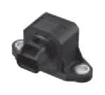
AGF1
Electrostatic capacitance detection sensor
1-axis acceleration sensor
GF1
Direct mount
Bracket
Features
● High precision, High
● High sensitivity
● Compact size
● RoHS compliant
reliability : Superior offset voltage temperature characteristics (±33 mg (Typ.))
: 1.333 to 3.0 V/g
: 58×36.5×33 mm 2.283×1.437×1.299 inch (Direct-mount type)
Typical Applications
● Automobiles
● Special vehicles
: 4WD-ABS control, neutral control, idling stop system and suspension control
: Inclination detection (for enhanced safety and operating efficiency) of agricultural
machine, construction machine and welfare vehicles
● Photovoltaic generation : Sun tracking panels
Ordering Information
AGF 1
1
Installation type
0 : Direct mount
1 : Bracket
Detection sensitivity
3 : 0.136 V/(m/s2) (1.333 V/g)
7 : 0.306 V/(m/s2) (3.0 V/g)
Operation power supply voltage
1 : 5 V.DC
2 : 12 V.DC
3 : 24 V.DC
Number of detectable axis (Method)
1 : 1-axis accleration sensor
(Electrostatic capacitance type)
Installation direction type
1 : Horizontal type
Product Types
Carton : 80 pcs. (Bracket), 150 pcs. (Direct mount)
Operation power Acceleration detection
Detection sensitivity
supply voltage
range
±11.76 m/s2 (±1.2 g) 0.136 V/(m/s2) (1.333 V/g)
5 V.DC
0.306 V/(m/s2) (3.0 V/g)
±4.9 m/s2 (±0.5g)
Product name
1-axis
accleration sensor
GF1
12 V.DC
Part number
AGF11311
Direct mount
AGF10711
±11.76 m/s2 (±1.2 g)
0.136 V/(m/s2) (1.333 V/g)
Direct mount
AGF10321
2
0.306 V/(m/s2) (3.0 V/g)
Direct mount
AGF10721
±11.76 m/s (±1.2 g)
2
0.136 V/(m/s ) (1.333 V/g)
Direct mount
AGF10331
±4.9 m/s2 (±0.5g)
0.306 V/(m/s2) (3.0 V/g)
Direct mount
AGF10731
±4.9 m/s (±0.5g)
2
24 V.DC
Installation
type
Bracket
Absolute Maximum Ratings
Product name
Maximum allowable voltage
Maximum applied
acceleration
AGF1□3□1
AGF1□7□1
Absolute maximum ratings
Remarks
AGF1□□21
AGF1□□31
AGF1□□11
(Power supply: 5 V.DC type) (Power supply: 12 V.DC type) (Power supply: 24 V.DC type)
V.DC
7
16
30
Max. Ta=25 °C 68 °F
Unit
g
15
Max.
5
Max.
Storage temperature range
°C °F
−30 to 85 –22 to 185
Operation temperature range
°C °F
−30 to 85 –22 to 185
g
5,000
Anti-shock characteristic
Grade of protection
✽
Max.
IP67
Note : ✽ Performance when matching connector is connected.
Design and specifications are each subject to change without notice. Ask factory for the current technical specifications before purchase and/or use.
Should a safety concern arise regarding this product, please be sure to contact us immediately.
00 Aug. 2015
�AGF1
Electrical Characteristics
● AGF1□3□1
(Sensitivity : 1.333 V/g type)
Item
Unit
Operation power supply voltage V.DC
Performance
AGF1□□21
AGF1□□31
AGF1□□11
(Power supply: 5 V.DC type) (Power supply: 12 V.DC type) (Power supply: 24 V.DC type)
5 V.DC±5 %
Acceleration detection range ✽1 g (°)
12 V.DC±10 %
24 V.DC±10 %
Remarks
−30 °C to +85 °C
–22 °F to +185 °F
±1.2 (90)
Current consumption
mA
Sensitivity
V/g
1.333±3 %
V
2.5±0.1
0g, Ta=20 °C 68 °F, Max.
−30 °C to +85 °C
–22 °F to +185 °F
Ta=20 °C 68 °F
V
±0.093
−30 °C to +85 °C
–22 °F to +185 °F
Offset voltage (0g)
Offset voltage temperature
characteristic
Other axis sensitivity
Non-linearity ✽2
Frequency response
10
15
%
±5
Ta=20 °C 68 °F
%FS
±1
Ta=20 °C 68 °F
Hz
10 to 15
–3 dB point
Clamping voltage VH ✽3
V
4.5
−
−
Typ.
✽3
V
0.5
−
−
Typ.
Clamping voltage VL
● AGF1□7□1
(Sensitivity : 3.0 V/g type)
Item
Unit
Operation power supply voltage V.DC
Performance
AGF1□□21
AGF1□□31
AGF1□□11
(Power supply: 5 V.DC type) (Power supply: 12 V.DC type) (Power supply: 24 V.DC type)
5 V.DC±5 %
Acceleration detection range ✽1 g (°)
12 V.DC±10 %
24 V.DC±10 %
Remarks
−30 °C to +85 °C
–22 °F to +185 °F
±0.5 (30)
Current consumption
mA
Sensitivity
V/g
3.0±3 %
V
2.5±0.1
0g, Ta=20 °C 68 °F, Max.
−30 °C to +85 °C
–22 °F to +185 °F
Ta=20 °C 68 °F
V
±0.21
−30 °C to +85 °C
–22 °F to +185 °F
%
±5
Ta=20 °C 68 °F
%FS
±1
Ta=20 °C 68 °F
Hz
10 to 15
–3 dB point
Offset voltage (0g)
Offset voltage temperature
characteristic
Other axis sensitivity
Non-linearity
✽2
Frequency response
10
15
✽3
V
4.5
−
−
Typ.
Clamping voltage VL ✽3
V
0.5
−
−
Typ.
Clamping voltage VH
Note : ✽1 The acceleration unit “g” means 9.8 m/s .
✽2 Maximum error from linear output that connects +1.2 g and –1.2 g output. (AGF1□3□1)
Maximum error from linear output that connects +0.5 g and –0.5 g output. (AGF1□7□1)
✽3 The 12 V and 24 V.DC operating power supply voltage types can also be compatible with the clamping voltage. Please consult us.
2
Design and specifications are each subject to change without notice. Ask factory for the current technical specifications before purchase and/or use.
Should a safety concern arise regarding this product, please be sure to contact us immediately.
00 Aug. 2015
�AGF1
Reference Data
1. Output characteristics
2. Inclination angle - Output voltage
characteristics
4.0
3.5
3.0
2.5
2.0
3.5
3.0
2.5
2.0
1.5
1.0
1.0
0.5
0.0
−2.0 −1.5 −1.0 −0.5 0.0 0.5 1.0 1.5 2.0
Acceleration (G)
0.5
0.0
−100−80 −60 −40 −20 0 20 40 60 80 100
Inclination angle ( °)
0
75
−2
−25
−50
−75
−100
−40 −20 0
20 40 60 80 100
−40 −4 +32 +68 +104 +140 +176 +212
Temperature (°C °F)
4
3
2
1
0
−1
−2
−3
−4
−5
−40 −20 0
20 40 60 80 100
−40 −4 +32 +68 +104 +140 +176 +212
Temperature (°C °F)
−4
50
0
5
5. Frequency characteristics
100
25
AGF11311
AGF10711
4.0
1.5
4. Offset voltage temperature
characteristics
Offset voltage change (measured value) (mg)
4.5
Output voltage (V)
AGF11311
AGF10711
Gain (dB)
Output voltage (V)
4.5
Sensitivity change (measured value) (%)
5.0
5.0
3. Sensitivity temperature
characteristics
−6
−8
−10
−12
−14
−16
−18
−20
1
10
Frequency (Hz)
60 100
Design and specifications are each subject to change without notice. Ask factory for the current technical specifications before purchase and/or use.
Should a safety concern arise regarding this product, please be sure to contact us immediately.
00 Aug. 2015
�AGF1
Dimensions
The CAD data of the products with a
mount (AGF10□□1)
2-7 dia.
2-0.275 dia.
36.5
1.437
58
2.283
44±0.5
1.732±0.020
Detection axis
● Direct
mark can be downloaded from: http://industrial.panasonic.com/
33
1.299
28
1.102
6
0.236
Matching connector:
Manufacturing company : Yazaki Corporation
Housing : 7283-8730-30
GND
VDD
Vout
unit : mm inch
(AGF11□□1)
a. .
di dia
5
6. .256
0
85
3.346
61.8
2.433
40
1.575
100610
JAPAN
AGF11311
Detection axis
● Bracket
Part No.
Lot No.
37
1.457
28
1.102
Matching connector :
Manufacturing company : Yazaki Corporation
Housing: 7283-8730-30
VDD
GND
Vout
unit : mm inch
Wiring Diagram
VDD
VDD
Sensor
Output
Vout
RL
GND
RL=Load resistance (Min.50 kΩ)
Design and specifications are each subject to change without notice. Ask factory for the current technical specifications before purchase and/or use.
Should a safety concern arise regarding this product, please be sure to contact us immediately.
00 Aug. 2015
�AGF1
NOTES
■ Before using the products, carefully check the
quality under actual use conditions to enhance
stability.
■ Wire connection
Correctly wire as in the connection diagram.
Reverse connection may damage the product and
degrade the performance.
■ Cleaning
Avoid ultrasonic cleaning as this may cause
disconnection of the wire.
■ Environment
• Avoid use and storage in the corrosive gas
(organic solvent, sulfurous acid and hydrogen
sulfide gases) which negatively affects the
product.
• Use surge absorbers as applying the external
surge voltage may damage the internal circuit.
• Malfunction may occur near electric noises from
static electricity, lightning, broadcast or amateur
radio stations and mobile phones.
• Avoid use in an environment where these products
cause dew condensation. When water attached to
the sensor chip freezes, the sensor output may be
fluctuated or damaged.
• Do not apply high-frequency oscillation, such as
ultrasonic waves, to the product.
• Do not use in direct sunlight or other comparable
light.
■ Other precautions
These specifications are for individual components.
Before use, carefully check the performance and
quality under actual use conditions to enhance
stability.
• Misconnection and the wrong range of
acceleration detection may invite the risk of
accidents.
• Avoid use beyond the specified acceleration
range, as such use may damage the product.
• Carefully handle as static electricity may damage
the product.
■ Special notes
We exert maximum efforts for quality control of the
product, Please mind also about the following.
1) To p r e v e n t o c c u r r e n c e o f u n e x p e c t e d
circumstances, please infor m us of the
specifications of your product, customers,
use conditions and details of the attachment
position.
2) Have sufficient margin values of driving/
performance guarantee described in the
specifications and apply safety measures with
double circuits, if serious effects on human
lives or property are predicted due to a quality
failure of the product. Those countermeasures
are also for the product liability.
3) A warranty period is one year after the delivery
to your company. Quality assurance is limited
to the items and the scopes described in the
specifications.
If a defect is found after the delivery, we will
promptly provide a replacement or change/
repair the defect part at the place of delivery
in good faith. Exceptions are below.
• Damages by a failure or a defect which
arose after the delivery.
• A f t e r t h e d e l i v e r y, w h e n s t o r i n g a n d
transporting, if conditions other than
conditions in the specifications are applied to
the product.
• Damages by unforeseen phenomenon which
cannot be predicted with the technologies
available at the time of delivery.
• Damages by natural and anthropogenic
disasters, such as earthquake, flood, fire
and war, which are beyond our reasonable
control.
Design and specifications are each subject to change without notice. Ask factory for the current technical specifications before purchase and/or use.
Should a safety concern arise regarding this product, please be sure to contact us immediately.
00 Aug. 2015
�Guidelines and precautions regarding the
technical information and use of our products
described in this online catalog.
■ If you want to use our products described in this online catalog for applications requiring
special qualities or reliability, or for applications where the failure or malfunction of the
products may directly jeopardize human life or potentially cause personal injury
(e.g. aircraft and aerospace equipment, traffic and transportation equipment, combustion
equipment, medical equipment, accident prevention, anti-crime equipment, and/or safety
equipment), it is necessary to verify whether the specifications of our products fit to such
applications. Please ensure that you will ask and check with our inquiry desk as to whether
the specifications of our products fit to such applications use before you use our products.
■ The quality and performance of our products as described in this online catalog only apply
to our products when used in isolation. Therefore, please ensure you evaluate and verify
our products under the specific circumstances in which our products are assembled in your
own products and in which our products will actually be used.
■ If you use our products in equipment that requires a high degree of reliability, regardless
of the application, it is recommended that you set up protection circuits and redundancy
circuits in order to ensure safety of your equipment.
■ The products and product specifications described in this online catalog are subject to
change for improvement without prior notice. Therefore, please be sure to request and
confirm the latest product specifications which explain the specifications of our products in
detail, before you finalize the design of your applications, purchase, or use our products.
■ The technical information in this online catalog provides examples of our products'
typical operations and application circuits. We do not guarantee the non-infringement of
third party's intellectual property rights and we do not grant any license, right, or interest
in our intellectual property.
■ If any of our products, product specifications and/or technical information in this online
catalog is to be exported or provided to non-residents, the laws and regulations of the
exporting country, especially with regard to security and export control, shall be observed.
■ The switchover date for compliance with the RoHS Directive/REACH Regulations varies
depending on the part number or series of our products.
■ When you use the inventory of our products for which it is unclear whether those products
are compliant with the RoHS Directive/REACH Regulation, please select "Sales Inquiry" in the
website inquiry form and contact us.
We do not take any responsibility for the use of our products outside the scope of the
specifications, descriptions, guidelines and precautions described in this online catalog.
01-Apr-19
�