GN (AGN)
High Sensitivity, with
100mW nominal operating
power, in a compact and
space saving case
GN RELAYS
FEATURES
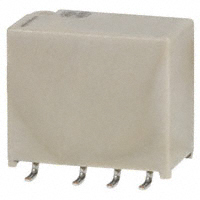
1. Compact slim body saves space.
Thanks to the small surface area of 5.7
mm 10.6 mm .224 inch .417 inch
and low height of 9.0 mm .354 inch,
the packaging density can be
increased to allow for much smaller
designs.
2. High sensitivity single side stable
type (Nominal operating power:
100mW) is available.
3. Outstanding surge resistance
Surge breakdown voltage between
contacts and coil:
2,500 V 210 s (Telcordia)
Surge breakdown voltage between
open contacts:
1,500 V 10160 s (FCC part 68)
4. The use of twin crossbar contacts
ensures high contact reliability.
AgPd contact is used because of its
good sulfide resistance. Adopting lowgas molding material. Coil assembly
molding technology which avoids
generating volatile gas from coil.
5. Increased packaging density
Due to highly efficient magnetic circuit
design, leakage flux is reduced and
changes in electrical characteristics
from components being mounted
close-together are minimized. This all
means a packaging density higher
than ever before.
6. Nominal operating power: 140 mW
7. Outstanding vibration and shock
resistance
Functional shock resistance: 750 m/s2
Destructive shock resistance:
1,000 m/s2
Functional vibration resistance:
10 to 55 Hz (at double amplitude of
3.3 mm .130 inch)
Destructive vibration resistance:
10 to 55 Hz (at double amplitude of
5 mm .197 inch)
8. Sealed construction allows
automatic washing.
9. Sealed according to RTIII (IP67)
TYPICAL APPLICATIONS
1. Telephone switchboard
2. Telecommunications equipment
3. Securits equipmeny
4. Test and measurement equipment
5. Electronic consumer and audio
visual equipment
ORDERING INFORMATION
AGN 2
0
Contact arrangement
2: 2 Form C
Operating function
0: Single side stable
1: 1 coil latching
6: High sensitivity single side
stable type
Type of operation
0: Standard type (B.B.M.)
Terminal shape
Nil: Standard PC board terminal
A: Surface-mount terminal A type
S: Surface-mount terminal S type
Nominal coil voltage (DC)
1H: 1.5V 03: 3V 4H: 4.5V 06: 6V 09: 9V
12: 12V 24: 24V
Packing style
Nil: Tube packing
X: Tape and reel packing (picked from 1/2/3/4 pin side)
Z: Tape and reel packing (picked from 5/6/7/8 pin side)
ds_61007_en_gn: 280114D
1
�GN (AGN)
TYPES
1. Standard PC board terminal
Nominal coil voltage
1.5V DC
3V DC
4.5V DC
6V DC
9V DC
12V DC
24V DC
Single side stable
Part No.
AGN2001H
AGN20003
AGN2004H
AGN20006
AGN20009
AGN20012
AGN20024
1 coil latching
Part No.
AGN2101H
AGN21003
AGN2104H
AGN21006
AGN21009
AGN21012
AGN21024
High sensitivity single side stable
Part No.
AGN2601H
AGN26003
AGN2604H
AGN26006
AGN26009
AGN26012
AGN26024
Single side stable
Part No.
AGN2001H
AGN20003
AGN2004H
AGN20006
AGN20009
AGN20012
AGN20024
1 coil latching
Part No.
AGN2101H
AGN21003
AGN2104H
AGN21006
AGN21009
AGN21012
AGN21024
High sensitivity single side stable
Part No.
AGN2601H
AGN26003
AGN2604H
AGN26006
AGN26009
AGN26012
AGN26024
1 coil latching
Part No.
AGN2101HZ
AGN21003Z
AGN2104HZ
AGN21006Z
AGN21009Z
AGN21012Z
AGN21024Z
High sensitivity single side stable
Part No.
AGN2601HZ
AGN26003Z
AGN2604HZ
AGN26006Z
AGN26009Z
AGN26012Z
AGN26024Z
Standard packing: Tube: 50 pcs.; Case: 1,000 pcs.
2. Surface-mount terminal
1) Tube packing
Nominal coil voltage
1.5V DC
3V DC
4.5V DC
6V DC
9V DC
12V DC
24V DC
: For each surface-mounted terminal identification, input the following letter. A type: A, S type: S
Standard packing: Tube: 50 pcs.; Case: 1,000 pcs.
2) Tape and reel packing
Nominal coil voltage
1.5V DC
3V DC
4.5V DC
6V DC
9V DC
12V DC
24V DC
Single side stable
Part No.
AGN2001HZ
AGN20003Z
AGN2004HZ
AGN20006Z
AGN20009Z
AGN20012Z
AGN20024Z
: For each surface-mounted terminal identification, input the following letter. A type: A, S type: S
Standard packing: Tape and reel: 500 pcs.; Case: 1,000 pcs.
Notes: 1. Tape and reel packing symbol “-Z” is not marked on the relay. “X” type tape and reel packing (picked from 1/2/3/4-pin side) is also available.
2. Please inquire if you require a relay, between 1.5 and 24 V DC, with a voltage not listed.
RATING
1. Coil data
1) Single side stable type
Nominal coil
voltage
Pick-up voltage
(at 20C 68F)
Drop-out voltage
(at 20C 68F)
Nominal operating
current
[10%] (at 20C 68F)
Coil resistance
[10%] (at 20C 68F)
Nominal operating
power
Max. applied voltage
(at 20C 68F)
140mW
150%V of
nominal voltage
1.5V DC
93.8mA
16
3V DC
4.5V DC
6V DC
9V DC
12V DC
46.7mA
31mA
23.3mA
15.5mA
11.7mA
64.2
145
257
579
1,028
9.6mA
2,504
230mW
120%V of
nominal voltage
Nominal operating
current
[10%] (at 20C 68F)
Coil resistance
[10%] (at 20C 68F)
Nominal operating
power
Max. applied voltage
(at 20C 68F)
1.5V DC
66.7mA
22.5
3V DC
4.5V DC
6V DC
9V DC
12V DC
24V DC
33.3mA
22.2mA
16.7mA
11.1mA
8.3mA
5.0mA
90
202.5
360
810
1,440
4,800
100mW
150%V of
nominal voltage
75%V or less of
nominal voltage*
(Initial)
10%V or more of
nominal voltage*
(Initial)
24V DC
2) 1 coil latching type
Nominal coil
voltage
Set voltage
(at 20C 68F)
75%V or less of
nominal voltage*
(Initial)
Reset voltage
(at 20C 68F)
75%V or less of
nominal voltage*
(Initial)
120mW
*Pulse drive (JIS C 5442-1996)
2
ds_61007_en_gn: 280114D
�GN (AGN)
3) High sensitivity single side stable type
Nominal operating
current
[10%] (at 20C 68F)
Coil resistance
[10%] (at 20C 68F)
1.5V DC
66.7mA
22.5
3V DC
4.5V DC
6V DC
9V DC
12V DC
33.3mA
22.2mA
16.7mA
11.1mA
8.3mA
90
202.5
360
810
1,440
5.0mA
4,800
Nominal coil
voltage
Set voltage
(at 20C 68F)
80%V or less of
nominal voltage*
(Initial)
Reset voltage
(at 20C 68F)
10%V or more of
nominal voltage*
(Initial)
24V DC
Nominal operating
power
Max. applied voltage
(at 20C 68F)
100mW
150%V of
nominal voltage
120mW
120%V of
nominal voltage
*Pulse drive (JIS C 5442-1996)
2. Specifications
Characteristics
Contact
Rating
Item
Arrangement
Initial contact resistance, max.
Contact material
Nominal switching capacity
Max. switching power
Max. switching voltage
Max. switching current
Min. switching capacity (Reference value)*1
Single side stable
Nominal operating
High sensitivity single side
power
stable type
1 coil latching
Specifications
2 Form C
Max. 100 m (By voltage drop 6 V DC 1A)
Stationary contact: AgPd+Au clad Movable contact: AgPd
1 A 30 V DC, 0.3 A 125 V AC (resistive load)
30 W (DC), 37.5 V A (AC) (resistive load)
110 V DC, 125 V AC
1A
10A 10 mV DC
140mW (1.5 to 12 V DC), 230mW (24 V DC)
100mW (1.5 to 12 V DC), 120mW (24 V DC)
Min. 1,000M (at 500V DC)
Measurement at same location as “Initial breakdown voltage” section.
750 Vrms for 1min. (Detection current: 10mA)
1,500 Vrms for 1min. (Detection current: 10mA)
1,000 Vrms for 1min. (Detection current: 10mA)
1,500 V (10160s) (FCC Part 68)
2,500 V (210s) (Telcordia)
Max. 50C
(By resistive method, nominal coil voltage applied to the coil; contact carrying current: 1A.)
Max. 4 ms [Max. 4 ms] (Nominal coil voltage applied to the coil, excluding contact bounce time.)
Max. 4 ms [Max. 4 ms] (Nominal coil voltage applied to the coil, excluding contact bounce
time.) (without diode)
Min. 750 m/s2 (Half-wave pulse of sine wave: 6 ms; detection time: 10s.)
Min. 1,000 m/s2 (Half-wave pulse of sine wave: 6 ms.)
10 to 55 Hz at double amplitude of 3.3 mm (Detection time: 10s.)
10 to 55 Hz at double amplitude of 5 mm
Min. 5 107 (at 180 times/min.)
Min. 105 (1 A 30 V DC resistive), 105 (0.3 A 125 V AC resistive) (at 20 times/min.)
Ambient temperature:
(Single side stable, 1 coil latching type) –40C to +85C –40F to +185F
(High sensitivity single side stable type) –40C to +70C –40F to +158F
Humidity: 5 to 85% R.H. (Not freezing and condensing at low temperature)
20 times/min.
Approx. 1 g .035 oz
Insulation resistance (Initial)
Breakdown voltage
(Initial)
Electrical
characteristics
Surge breakdown
voltage (Initial)
Between open contacts
Between contact and coil
Between contact sets
Between open contacts
Between contacts and coil
Temperature rise (at 20C 68F)
Operate time [Set time] (at 20C 68F)
Release time [Reset time] (at 20C 68F)
Mechanical
characteristics
Expected life
Conditions
Functional
Destructive
Functional
Vibration resistance
Destructive
Mechanical
Electrical
Shock resistance
Conditions for operation, transport and storage*2
Max. operating speed (at rated load)
Unit weight
Notes:
*1 This value can change due to the switching frequency, environmental conditions, and desired reliability level, therefore it is recommended to check this with the actual load.
*2 Refer to “6. Usage, Storage and Transport Conditions“ in AMBIENT ENVIRONMENT section in Relay Technical Information.
REFERENCE DATA
1. Max. switching capacity
2. Life curve
3. Mechanical life
Tested sample: AGN2004H, 15 pcs.;
Operating speed: 180 times/min.
0.3
4
3.5
50
40
Pick-up voltage
Max.
3
30
DC 30V resistive load
20
Voltage, V
1.0
No. of operations, × 104
Switching current, A
100
DC resistive load
AC resistive load
Min.
2.5
2
Drop-out voltage
1.5
AC 125V
resistive load
10
Max.
Min.
1
0.5
30
100
Contact voltage, V
ds_61007_en_gn: 280114D
0
0.2
0.4
0.6
0.8
1.0
Switching current, A
1.2
0
0
10
30
50
No. of operations, ×104
3
�GN (AGN)
4. Electrical life (1A 30V DC resistive load)
5. Coil temperature rise
Tested sample: AGN2004H, 6 pcs.
Operating speed: 20 cpm
Tested sample: AGN2004H, AGN20024, 6 pcs.
Point measured: Inside the coil
Ambient temperature: Room temperature
Change of contact resistance
100
90
90
80
Pick-up voltage
70
Max.
Min.
60
50
Drop-out voltage
40
Max.
30
Min.
20
70
N.C. contact
N.O. contact
80
70
60
50
X
X
40
50
5
20
30
10
0
0
10
1A
0A
30
10
0
0
1A
0A
40
20
10
4.5V DC type
24V DC type
60
Temperature rise, °C
100
Contact resistance, mΩ
Ratio against the rated voltage, %V
Change of pick-up and drop-out voltage
5
No. of operations, ×104
0
10
100
110
120
130
140
150
Coil applied voltage, %
No. of operations, ×104
6-(2). Operate and release time (with diode)
7. Ambient temperature characteristics
Tested sample: AGN2004H, 6 pcs.
Tested sample: AGN2004H, 6 pcs.
Tested sample: AGN2004H, 6 pcs.
3
Operate time
Release time
Operate and release time, ms
Operate and release time, ms
3
2.5
Max.
2
Min.
1.5
1
Max.
Min.
Operate time
Release time
2.5
Max.
2
1.5
1
0.5
0.5
0
0
Drop-out
voltage
-40 -20
0
Min.
Max.
Min.
Rate of change, %V
6-(1). Operate and release time (without diode)
Pick-up
voltage
50
40
30
20
x
x
10
60
80 100
20 40
-10
Ambient temperature, °C
-20
-30
-40
80
90
100
110
120
80
90
Coil applied voltage, %V
100
110
-50
120
Coil applied voltage, %V
9-(1). Influence of adjacent mounting
9-(2). Influence of adjacent mounting
Tested sample: AGN2004H
Tested sample: AGN20012, 6 pcs.
Tested sample: AGN20012, 6 pcs.
Deenergized condition
Energized condition
X
1,000m/s2
Z
1,000m/s2
1,000m/s2
Z'
1,000m/s2
X'
1,000m/s2
Y'
10
5
Pick-up voltage
0
ON
Rate of change, %V
Y
1,000m/s2
ON
-5
ON
-10
10
OFF
5
Rate of change, %V
Z X X'
Rate of change, %V
Z'
Y
Y'
Rate of change, %V
8. Malfunctional shock
OFF
Drop-out voltage
0
OFF
-5
-10
0
PC board pattern
Standard type
5.70±0.3
.224±.012
10.60±0.3
.417±.012
7.60
.299
3.20
.126
3.20
.126
(0.50) 9.00±0.3
(.020) .354±.012
0.40±0.1
.016±.004
(1.50)
(.059)
4
ON
Pick-up voltage
0
-5
ON
ON
-10
10
OFF
5
Drop-out voltage
0
OFF
-5
OFF
2
4
6
8 10 12
.079 .157 .236 .315 .394 .472
Inter-relay distance , mm inch
CAD Data
Data from our Web site.
Download CAD
External dimensions
CAD Data
5
-10
0
2
4
6
8 10 12
.079 .157 .236 .315 .394 .472
Inter-relay distance , mm inch
DIMENSIONS (mm inch))
1. PC board terminal
10
2.20±0.15
.087±.006
3.20±0.15
.126±.006
3.50±0.3
.138±.012
0.25±0.1
.010±.004
3.20±0.15
.126±.006
0.85 dia.
.033 dia.
2.20
.087
Tolerance: 0.1 .004
Schematic (Bottom view)
Single side stable
High sensitivity
single side stable
1
2 3 4
8
7 6 5
1 coil latching
1
2 3 4
8
7 6 5
Direction indication
Direction indication
(Deenergized condition)
(Reset condition)
ds_61007_en_gn: 280114D
�GN (AGN)
2. Surface-mount terminal
CAD Data
Suggested mounting pad (Tolerance: 0.1 .004)
Single side stable/1 coil latching/High sensitivity single side stable
External dimensions
Single side stable/1 coil latching/High sensitivity single side stable
Type
5.70±0.3
.224±.012
10.60±0.3
.417±.012
0.25±0.1
.010±.004
A type
0.40±0.1
.016±.004
(1.50)
(.059)
2.20
.087
3.20
.126
(0.50) 9.00±0.3
(.020) .354±.012 Max. 10.00
.394
3.10
.122
5.30
.209
3.20±0.15
.126±.006
2.20±0.15
.087±.006
3.20±0.15
.126±.006
0.80
.031
7.40±0.3
.291±.012
5.70±0.3
.224±.012
10.60±0.3
.417±.012
2.20
.087
3.20
.126
(0.50) 9.00±0.3
(.020) .354±.012 Max. 10.00
.394
0.25±0.1
.010±.004
S type
3.20±0.15
.126±.006
2.20±0.15
.087±.006
3.20±0.15
.126±.006
0.40±0.1
.016±.004
(1.50)
(.059)
2.25
.089
4.45
.175
0.80
.031
5.70±0.3
.224±.012
Schematic (Top view)
Single side stable
High sensitivity single side stable
8
7 6 5
1
2 3 4
1 coil latching
8
7 6 5
1
2 3 4
Direction indication
Direction indication
(Deenergized condition)
(Reset condition)
NOTES
1. Packing style
1) The relay is packed in a tube with the
relay orientation mark on the left side, as
shown in the figure below.
(S type)
(1)-2 Tape dimensions
Relay polarity bar
(Z type)
1.50 +0.1
0 dia.
.059 +.004
dia.
0
Orientation (indicates PIN No.1)stripe
2.00
.079
4.00 2.0 dia.
.157 .079 dia.
1.75
.069
10.70±0.2
.421±.008
0.40
.016
11.50
.453 24.00±0.3
.945±.012
11.10
.437
GN relays
16.00
.630
6.3
.248
Tape coming out direction
Stopper (green)
Stopper (red)
mm inch
mm inch
Relay polarity bar
(Z type)
0.40
.016
4.00
.157
2.00
.079
1.50 +0.1
0 dia.
.059 +.004
dia.
0
11.50
.453
1.75
.069
11.10
.437
10.70±0.2
.421±.008
GN relays
2.00 dia.
.079 dia.
16.00
.630
General tolerance ±0.1 mm .004 inch
(2) Dimensions of plastic peel
2) Tape and reel packing
(A type)
(1)-1 Tape dimensions
2. Automatic insertion
To maintain the internal function of the
relay, the chucking pressure should not
exceed the values below.
Chucking pressure in the direction A:
4.9 N {500gf} or less
Chucking pressure in the direction B:
9.8 N {1 kgf} or less
Chucking pressure in the direction C:
9.8 N {1 kgf} or less
24.00±0.3
.945±.012
8.00
.315
Tape coming out direction
General tolerance ±0.1 mm .004 inch
A
C
B
2.0
.079
13 dia.
.512 dia.
21 dia.
.827 dia.
380 dia.
14.961 dia.
80 dia.
3.150 dia.
Please chuck the
portion.
Avoid chucking the center of the relay.
In addition, excessive chucking pressure
to the pinpoint of the relay should be
avoided.
For Cautions for Use, see Relay Technical Information.
ds_61007_en_gn: 280114D
5
�


 工商网监
湘ICP备2023018690号
工商网监
湘ICP备2023018690号
