KS1 SIGNAL CONVERTER (AKS1)
RS232C/RS485 Data can be
easily monitored by LAN
KS1 SIGNAL
CONVERTER
FEATURES
• The connectors are located on the front panel. Easy to
connect
• Easy to operate
• Can be connected to the LAN without the need of
switching between RS232C and RS485 signals
• Easy-to-install DIN-rail-mountable type
Up to 99 meters
KW7M Eco-POWER METER
RS485
LAN
KW4M Eco-POWER METER
PC
KS1 Signal Converter
Compliance with RoHS Directive
PRODUCT TYPES
� Main unit
Rated voltage
24 V DC
KS1 Signal Converter
Signal conversion specifications
Ethernet ⇔ RS232C/RS485
Model number
AKS1202
� Options
Product name
Power supply unit for FP0
Power supply cable for FPΣ*
Screwdriver for terminal block
Descriptions
Input: 100 to 240 VAC, Output: 24 VDC, 0.7 A
1 piece, 1 m length
Using when wiring Phoenix terminal
Model number
AFP0634
AFPG805
AFP0806
* Included with product
� Setting software
Product name
Configurator WD
Descriptions
IP address searching tool software for KS1
Remarks
You can download from our website (free of charge)*
Descriptions
Detailed explanation of KS1 Signal Converter usage (pdf)
Remarks
You can download from our website (free of charge)*
� Manual
Product name
KS1 Signal Converter User’s manual
* Customer registration is required to download data.
All Rights Reserved © COPYRIGHT Panasonic Electric Works Co., Ltd.
�KS1 SIGNAL CONVERTER (AKS1)
SPECIFICATIONS
� General specifications
Rated voltage
Operating voltage range
Inrush current
Current consumption
Allowed momentary power off time
Fuse
Terminal screw
Ambient temperature
Storage temperature
Ambient humidity
Breakdown voltage (initial)
24 V DC
90 to 110%V of rated voltage
12 A or less
200 mA or less
10 ms
Built-in type
M2
0 to 55°C
–20 to +75°C
30 to 85% RH (at 20°C, non-condensing)
500 V AC 1 minute
RS485 terminals ⇔ Combined power supply
100 MΩ or higher
and ground terminals
(500 V DC using an insulation resistance meter)
10 to 55 Hz, 1 cycle/min.: double amplitude of 0.75 mm, 1 hour on 3 axes
294 m/s2 or more, 5 times on 3 axes
25 × 60 × 90
Approx. 80 g
Insulation resistance (initial)
Vibration resistance
Shock resistance
Dimensions
Weight
� Communication specifications Interface: Ethernet
Interface
Connector shape
Transmission
specifications
Transmission speed
Transmission method
Max. segment length
Communication cable
Protocol
Functions
IEEE802.3u, 10BASE-T/100BASE-TX
RJ45
10 Mbps/100 Mbps
Base band
100 m
Category 5 UTP cable
MODBUS TCP (RTU, ASCII), TCP/IP*8
Auto negotiation function, MDI/MDI-X, Auto crossover function
Ethernet is a registered trademark of Xerox Corporation.
� Communication specifications Interface: RS232C and RS485
RS232C (non-insulated)
RS485 (insulated)
COM1
COM2
1 : 1 communication
1 : N communication
1 station
99 stations max.
Full duplex
Half duplex
Start-stop synchronization
—
15 m
Max. 1200 m *2, 3
2400, 4800, 9600, 19200, 38400, 57600 and 115200bps
3
3
Setting range: 10 ms to 300 s
Setting range: 10 ms to 300 s
Setting range: 0 to 1800 s (Not disconnected when set to “0”.) *7
8 bits fixed
Odd/Even/None
1 bit/2 bits
CR, CR+LF, None
Command/Response system
Notes: 1. COM1 and COM2 can be used simultaneously.
2. When connecting a commercially available device, please confirm operation using the actual
device. In some case, the number of stations, transmission distance, and communication speed
vary depending on the connected device.
3. The values for the transmission distance, communication speed and number of stations should be
within the values noted in the graph.
4. Number of TCP connections on the Ethernet side that can be connected to COM1 and COM2.
5. Length of time until the communication from the Ethernet side cuts off due to no response from
each remote unit.
In case of 61s or more, time can be set in units of 1s.
6. Length of time until the signal converter side automatically ends the connection when the state of
no communication from the Ethernet side with communication established exceeds the set time.
7. In case of setting “0: No disconnected”, it cuts the connection automatically when no
communication continues for two hours.
8. For transport layer protocol of Ethernet, MODBUS TCP (RTU, ASCII) can be selected in addition
to TCP (from the main unit firmware V1.03 or higher).
For transmission speed 115.2 kbps
For transmission speed 57.6 kbps
Number of stations
Interface
Conversion COM port*1
Communication style
Number of connectable stations
Communication method
Synchronous method
Transmission distance
Communication speed
Number of connectable connections*4
COM receive time out*5
Non-communication time before disconnection*6
Data length
Parity
Conversion and transmission
format
Stop bit
End code
Serial ⇔ Ethernet conversion
99
70
40
0
700
1000
Transmission distance (m)
All Rights Reserved © COPYRIGHT Panasonic Electric Works Co., Ltd.
1200
�KS1 SIGNAL CONVERTER (AKS1)
PARTS NAMES AND DIMENSIONS (mm)
The CAD data of the products with a CAD Data mark
can be downloaded from: http://panasonic-electric-works.net/ac
Tolerance: ±1.0
CAD Data
(9.5)
25.0
Communication setting switch 2
60.0
Connector for LAN: RJ45
Reset switch
Labeling location
O
N
Communication
setting switch 1
POWER
Status display LED
1
2
3
4
RESET
ERROR
LINK
/ACT
MODE
1
2
3
4
RS232C
RD
SPEED
Input/Output display LED
(LAN)
90.0
OFF ON
232C
SD
SD
RD
SG
485
+
SD
Input/Output display LED
(RS232C/RS485)
RD
RS485
+
-
Signal
Converter
DIN hook
Expansion
hook
KS1
E
(24V DC)
Power connector
Power cable (option): AFPG805
Terminal block for RS232C/RS485
Terminal screwdriver: AFP0806
Tightening torque: 0.22 to 0.25 N·m
TERMINAL ARRANGEMENT
Be sure to wire correctly according to the terminal arrangement and wiring diagrams.
� LAN Connector
Connector: RJ45
Cable: UTP (Category 5 or more)
This unit recognizes automatically the cable,
cross or straight.
Select cable according to the connected devices.
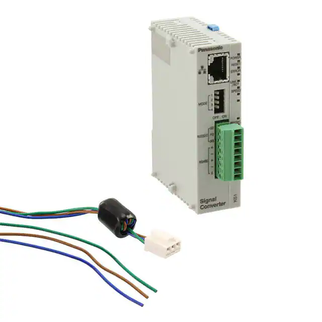
� Power supply connector
Use the attached power supply cable (AFPG805) to connect
power supply.
Mark
+
−
Attached power supply cable
Brown
24V DC
Blue
0V
Green
Function earth
� RS232C/RS485 terminal block
Terminal No.
No.
SD
1
1
RS232C
SD
RS232C RD
2
2
RS232C
RD
SG
3
3
RS232C
SG
4
4
RS485
5
5
RS485
6
6
RS485
7
7
RS485
8
8
RS485
RS485
E
Terminal shape
Notes: 1. Please use twisted lines for power supply line (brown and blue) in order to
reduce the noise effect from outside.
2. Please use a power supply of the insulation type with built-in protection
circuit in order to protect against an abnormal voltage from power supply
line.
3. Regulator on the unit is non-insulation type.
4. Use power supply voltage within the range of allowable voltage.
Rated voltage
Operating voltage range
24V DC
21.6 to 26.4V DC
All Rights Reserved © COPYRIGHT Panasonic Electric Works Co., Ltd.
Functions
Terminal name
E
�KS1 SIGNAL CONVERTER (AKS1)
COMMUNICATION SETTING
You can set communication conditions by two methods, using the communication set switches on the front of main unit and
using the setting software (Configurator WD).
� Set by the communication set switches
Use 4 Communication set switch 1 and 5 Communication set
switch 2 to set communication setting.
MODE
1
4
Communication
set switch 1
ON
O
N
ON
1
5
Communication
set switch 2
2
MODE
3
Item
OFF
Transmission
speed
ON
2
3
4
Below table
Setting method
Software
1
2
3
4
Parity
Parity
Stop bit
Vacant
Not available
Even number
2
Hardware *1
Available
Odd number
1
OFF
4
3
2
1
4
ON
4 Communication
set switch 1
5 Communication
set switch 2
MODE 1
OFF
ON
OFF
ON
OFF
ON
OFF
ON
MODE 2
OFF
OFF
ON
ON
OFF
OFF
ON
ON
MODE 3
OFF
OFF
OFF
OFF
ON
ON
ON
ON
Transmission speed
115200bps
2400bps
4800bps
9600bps
19200bps
38400bps
57600bps
115200bps
Notes: 1. Only when MODE 4 of 4 switch 1 is set to ON (Hardware), 4 and 5
switches’ setting is available.
2. When MODE 4 of 4 switch 1 is set to OFF (Software), 4 and 5 switches’
setting is not available.
3. Data length is fixed with 8 bit.
4. Setting conditions are read when power turns on. You should set them
before power turns on.
If you change the settings while power turns on, some malfunctions might
be occurred.
5. When setting by hardware (communication set switches), RS232C and
RS485 communication settings are set as same. If individual setting for
RS232C and RS485 is required, use the setting software.
� Set by setting software Configurator WD
You can download the setting software “Configurator WD” from our website.
http://panasonic-electric-works.net/ac
Please refer to the help in Configurator WD for the way to set.
Note: In case of setting by “Configurator WD”, MODE 4 of 4 switch 1 should be set to OFF (software).
CAUTIONS FOR SAFETY
Please use correctly only after you have thoroughly read “User’s Manual, Instruction Manual, and Catalog”.
All Rights Reserved © COPYRIGHT Panasonic Electric Works Co., Ltd.
�KS1 SIGNAL CONVERTER (AKS1)
CAUTIONS BEFORE USING
� Do not use the Unit in the following environments.
• Where the unit will be exposed to direct sunlight and where the ambient temperature is outside the range of 0 to 55°C.
• Where the ambient humidity is outside the range of 30 to 85% RH (at 20°C non-condensing) and where condensation might occur
by sudden temperature changes
• Where inflammable or corrosive gas might be produced
• Where the unit will be exposed to excessive airborne dust or metal particles
• Where the unit will be exposed to water, oil or chemicals
• Where organic solvents such as benzene, paint thinner, alcohol, or strong alkaline solutions such as ammonia or caustic soda might
adhere to the product
• Where direct vibration or shock might be transmitted to the product, and where water might wet the product
• Places unaffected by power transmission lines, high voltage equipment, power cables, power equipment, radio transmitters and any
other equipment that would generate high switching surge.
� Please use the Unit according to the specifications described in this manual. Otherwise, it may malfunction or cause fire
and an electric shock.
• Connect to the power supply in compliance with the rating.
• Refer to the wiring diagram to ensure proper wiring for the power supply, input and output.
• Do not perform wiring or installation with a live line. It may also lead to circuit burnout or fire.
• Do not add voltage and current to an output terminal from outside.
� Static electricity
• Discharge static electricity touching the grounded metal etc. when you touch the unit.
• Excessive static electricity might be generated especially in a dry place.
� Cleaning
• Wipe dirt of the main unit with soft cloth etc. When thinner is used, the unit might deform or be discolored.
� Power supply
• Connect a breaker to the voltage input part for safety reasons and to protect the device.
• Do not turn on the power supply or input until all wiring is completed.
• Do not add abnormal voltage directly, otherwise it might damage internal circuit.
� Before power on
Please note the following points when turning on power at the first time.
• Confirm there are neither wiring rubbish nor especially an electrical conduction when installed.
• Confirm neither the power supply wiring, the I/O wiring nor the power-supply voltage are wrong.
• Tighten the installation screw and the terminal screw surely.
• Use an electric wire applicable to the rated current.
� Others
• Please note that it might take time to approve the communication again after power on and breaking the communication.
• This product is designed to be used only with our options. Options from other companies are not compatible.
All Rights Reserved © COPYRIGHT Panasonic Electric Works Co., Ltd.
�