LZ (ALZ)
VDE
16A LOW PROFILE
POWER RELAY
28.8
1.134
LZ RELAYS (ALZ)
FEATURES
12.5
.492
15.7
.618
mm inch
RoHS Directive compatibility information
http://www.nais-e.com/
1. Low profile size: Height 15.7 mm
28.8 (L)×12.5 (W)×15.7(H) mm
1.134 (L)×.492 (W)×.618(H) inch
2. High insulation resistance
Creepage distance and clearances
between contact and coil: Min. 10 mm
3. UL coil insulation class B (85°C
185°F) or class F (105°C 221°F).
4. EN60335-1 GWT compliant (Tested
by VDE) type available (Class B
insulation type only)
5. Pb free and Cd free
6. Low operating power
• Nominal operating power: 400mW
7. Conforms to the various safety
standards:
• UL, C-UL, VDE approved.
SPECIFICATIONS
Contact
Characteristics
Arrangement
Initial contact resistance, max.
(By voltage drop 6 V DC 1 A)
Contact material
Rating
(resistive
load)
Expected life
(min.
operations)
1 Form A, 1 Form C
100 mΩ
AgSnO2 type
Nominal switching capacity
Max. switching power
Max. switching voltage
Max. switching current
Min. switching capacity#1
(Reference value)
Mechanical (at 180 cpm)
Electrical (at 20 cpm)
(Rated load)
16 A 250 V AC
4,000 V A
440 V AC
16 A
100 mA, 5 V DC
1 × 10⁷
N.O.: 105
N.C.: 5 × 10⁴
Coil
Max. operating speed
Initial insulation resistance*1
Between open contacts
Between contacts and
coil
Initial surge voltage between contact
and coil*3
Operate time*4 (at nominal voltage)
Release time (with diode)*4
(at nominal voltage)
Initial
breakdown
voltage*2
Nominal operating power
400 mW
#1 This value can change due to the switching frequency, environmental conditions,
and desired reliability level, therefore it is recommended to check this with the
actual load.
* Specifications will vary with foreign standards certification ratings.
*1 Measurement at same location as “Initial breakdown voltage” section.
*2 Detection current: 10mA
*3 Wave is standard shock voltage of ±1.2 × 50µs according to JEC-212-1981
*4 Excluding contact bounce time.
*5 Half-wave pulse of sine wave: 11 ms; detection time: 10 µs
*6 Half-wave pulse of sine wave: 6 ms
*7 Detection time: 10 µs
*8 Refer to 6. Conditions for operation, transport and storage mentioned in
AMBIENT ENVIRONMENT
*9 Class F type is ambient temperature 105°C 221°F.
Max. 15ms (at 20°C 68°F)
Max. 5ms (at 20°C 68°F)
Humidity
5 to 85% R.H.
Vibration resistance
Destructive
Conditions for
operation, transport
and storage*8
(Not freezing and
condensing at low
temperature)
Unit weight
10,000 V
Ambient
temp.
Functional*5
Destructive*6
Functional*7
Remarks
5,000 Vrms for 1 min.
Max. 55°C
with nominal coil voltage
and at 16 A contact carrying
current (resistance method)
100 m/s2{approx. 10 G}
1,000 m/s2{approx. 100 G}
10 to 55Hz
at double amplitude of
1.5mm (NO), 0.82mm (NC)
10 to 55Hz
at double amplitude of 1.5mm
–40°C to +85°C
–40°F to +185°F (Class B)*9
Temperature rise (20°C 68°C)
Shock resistance
20 cpm (at rated load)
Min. 1,000 MΩ (at 500 V DC)
1,000 Vrms for 1 min.
TYPICAL APPLICATIONS
• HVAC
• Oven ranges
• Refrigerators
All Rights Reserved © COPYRIGHT Matsushita Electric Works, Ltd.
Approx. 12 g .42 oz
�LZ (ALZ)
ORDERING INFORMATION
Ex.
A
LZ
1
1
Product
name
Contact
arrangement
Protective
construction*
LZ
1: 1 Form C
2: 1 Form A
1: Flux-resistant type
B
12
Coil insulation class
B: Class B insulation
F: Class F insulation
W
Coil voltage,
V DC
05: 5
09: 9
12: 12
18: 18
24: 24
48: 48
Flame resistance and
tracking resistance
Nil: —
T: EN60335-1 (Conform)
(Class B insulation only)
Packing style
Nil: Tube packing
W: Carton packing
UL, C-UL, VDE approved type is standard.
Notes: 1. Sealed type is also available. Please consult us.
2. Tube packing: Inner carton: 20pcs.; Case: 800pcs.
3. Carton packing: Inner carton: 100pcs.; Case: 500pcs.
4. Carton packing symbol “W” is not marked on the relay.
TYPES
Contact arrangement
Coil voltage, V DC
5
9
12
18
24
48
5
9
12
18
24
48
1 Form A
1 Form C
Tube packing
Class B
ALZ21B05
ALZ21B09
ALZ21B12
ALZ21B18
ALZ21B24
ALZ21B48
ALZ11B05
ALZ11B09
ALZ11B12
ALZ11B18
ALZ11B24
ALZ11B48
Class F
ALZ21F05
ALZ21F09
ALZ21F12
ALZ21F18
ALZ21F24
ALZ21F48
ALZ11F05
ALZ11F09
ALZ11F12
ALZ11F18
ALZ11F24
ALZ11F48
Carton packing
Class B
Class F
ALZ21B05W
ALZ21F05W
ALZ21B09W
ALZ21F09W
ALZ21B12W
ALZ21F12W
ALZ21B18W
ALZ21F18W
ALZ21B24W
ALZ21F24W
ALZ21B48W
ALZ21F48W
ALZ11B05W
ALZ11F05W
ALZ11B09W
ALZ11F09W
ALZ11B12W
ALZ11F12W
ALZ11B18W
ALZ11F18W
ALZ11B24W
ALZ11F24W
ALZ11B48W
ALZ11F48W
Note: EN60335-1 GWT compliant types available. When ordering, please add suffix “T”.
Ex) ALZ21B12T , ALZ21B05TW
COIL DATA
Nominal voltage,
V DC
5
9
12
18
24
48
Pick-up voltage,
V DC (max.)
3.5
6.3
8.4
12.6
16.8
33.6
Drop-out voltage,
V DC (min.)
0.5
0.9
1.2
1.8
2.4
4.8
Coil resistance,
Ω (±10%)
63
203
360
810
1,440
5,760
Nominal operating
current, mA (±10%)
80
44.4
33.3
22.2
16.7
8.3
Nominal operating
power, mW
400
All Rights Reserved © COPYRIGHT Matsushita Electric Works, Ltd.
Maximum allowable
voltage, V DC
6.5
11.7
15.6
23.4
31.2
62.4
�LZ (ALZ)
DIMENSIONS
mm inch
1. 1 Form A type
PC board pattern (Bottom view)
5
.197
15.7
0.5 .618
.020
6-1.3 dia.
6-.051 dia.
7.5
.295
2.5
.098
0.5
.020
20
.787
28.8
1.134
5
.197
0.5
.020 3.5
.138
7.5
.295
12.5
.492
0.8
.031
20
.787
Tolerance: ±0.1 ±.004
Schematic (Bottom view)
Dimension:
Tolerance
Max. 1mm .039 inch:
±0.1 ±.004
1 to 3mm .039 to .118 inch: ±0.2 ±.008
Min. 3mm .118 inch:
±0.3 ±.012
Coil
2. 1 Form C type
PC board pattern (Bottom view)
5
5
.197 .197
15.7
0.5 .618
.020
8-1.3 dia.
8-.051 dia.
7.5
.295
0.5
.020
2.5
.098
20
.787
28.8
1.134
5
5
.197 .197
0.5
.020 3.5
.138
7.5
.295
12.5
.492
0.8
.031
20
.787
Tolerance: ±0.1 ±.004
Schematic (Bottom view)
Dimension:
Tolerance
Max. 1mm .039 inch:
±0.1 ±.004
1 to 3mm .039 to .118 inch: ±0.2 ±.008
Min. 3mm .118 inch:
±0.3 ±.012
Coil
REFERENCE DATA
2. Coil temperature rise
55
Temperature rise, °C
Contact current, A
100
AC resistive load
10
3. DC breaking capacity
0A
16A
100
20°C
50
20°C
45
40
85°C
85°C
105°C
105°C
35
Switching current, A
1. Max. switching power
10
DC resistive load
1
30
25
1
1
10
30
100
Contact voltage, V
1000
20
0
100 105 110 115 120 125 130 135
Coil applied voltage, %V
For Cautions for Use, see Relay Technical Information
All Rights Reserved © COPYRIGHT Matsushita Electric Works, Ltd.
0
10
100
Switching voltage, V
1000
�
很抱歉,暂时无法提供与“ALZ22B12”相匹配的价格&库存,您可以联系我们找货
免费人工找货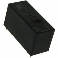


 工商网监
湘ICP备2023018690号
工商网监
湘ICP备2023018690号
