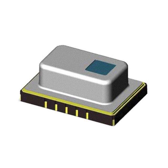
Infrared Array Sensor Grid-EYE (AMG88)
Infrared Array Sensor
Grid-EYE
High Precision Infrared Array Sensor based on Advanced MEMS Technology
Features
● Temperature detection of two-dimensional area: 8 × 8 (64
● Digital output (capability of temperature value output)
● Compact SMD package (adaptively to reflow mounting)
● RoHS compliant
pixels)
Typical Applications
● High function home appliances (microwaves and air-conditioners)
● Energy saving at office (air-conditioning/lighting control)
● Digital signage
● Automatic doors/elevators
Ordering Information
AMG 8 8
Vertical pixel
8 : 8 pixels
Horizontal pixel
8 : 8 pixels
Applied voltage
3 : 3.3 V.DC
5 : 5 V.DC
Applied voltage
1 : High gain
2 : Low gain
Types
Number of pixel
Product name
Infrared array sensor
64
Grid-EYE
(Vertical 8 × Horizontal 8 Matrix)
Operating voltage
3.3 V.DC
5.0 V.DC
Amplification factor
Part number
High gain
AMG8831
Low gain
AMG8832
High gain
AMG8851
Low gain
AMG8852
Tape and reel package : 1,000 pcs.
Rating
Item
Applied voltage
Performance
High gain
Low gain
3.3 V.DC±0.3 V.DC or 5.0 V.DC±0.5 V.DC
Temperature range of measuring object
0 °C to 80 °C +32 °F to +176 °F
−20 °C to 100 °C –4 °F to +212 °F
Operating temperature range
0 °C to 80 °C +32 °F to +176 °F
−20 °C to 80 °C –4 °F to +176 °F
Storage temperature range
−20 °C to 80 °C –4 °F to +176 °F
−20 °C to 80 °C –4 °F to +176 °F
Design and specifications are each subject to change without notice. Ask factory for the current technical specifications before purchase and/or use.
Should a safety concern arise regarding this product, please be sure to contact us immediately.
00 Aug. 2015
�Infrared Array Sensor Grid-EYE (AMG88)
Absolute Maximum Ratings
Item
Absolute maximum ratings
Terminal
−0.3 V.DC to 6.5 V.DC
VDD
−0.3 V.DC to VDD +0.3 V.DC
SCL, SDA, AD_SELECT
Applied voltage
Input voltage
Output sink current
−10 mA to 10 mA
INT, SDA
1 kV
All terminals
200 V
All terminals
Static electricity (Human body model)
Static electricity (Machine model)
Characteristics
Performance
High gain
Low gain
Typical ±3.0 °C ±5.4 °F
Typical ±2.5 °C ±4.5 °F
Max. 5 m 16.404 ft
Typical 60 °
Within Typical ±5.6 °
Typical 4.5 mA (normal mode)
Typical 0.2 mA (sleep mode)
Typical 0.8 mA (stand-by mode)
Typical 50 ms (Time to enable communication after setup)
Typical 15 s (Time to stabilize output after setup)
Item
Temperature accuracy
Human detection distance ✽1
Viewing angle
Optical axis gap
Current consumption
Setup time
Note: ✽1 To have more than 4 °C 7.2 °F of temperature difference from background
Detection object size: 700 × 250 mm 27.559 × 9.843 inch (Assumable human body size)
Performance
Item
Number of pixel
External interface
Frame rate
Performance
64 (Vertical 8 × Horizontal 8 Matrix)
I2C (fast mode)
Typical 10 frames/sec or 1 frame/sec
Normal
Sleep
Stand-by (10 sec or 60 sec intermittence)
Temperature output
No moving average or Twice moving average
0.25 °C
2
2 (I C slave address)
−20 °C to 80 °C –4 °F to +176 °F
0.0625 °C
Operating mode ✽1
Output mode
Calculate mode
Temperature output resolution
Number of sensor address
Thermistor output temperature range
Thermistor output resolution
Note: ✽1 Normal Mode : normal operation mode; Sleep Mode: detection is off (output and data reading not possible); Standby Mode: 1 frame measuring
intermittently every 10 or 60 sec.
Internal Circuit
3.3 V.DC or 5 V.DC
Infrared array sensor
Sensor chip
2
VDD
SDA
ROM
9
I2C I/F
3
SCL
Selector
Control
Capacitor
10 μF
5
Gain
amp
GND
ADC
4
6
AD_SELECT
INT
Thermistor
GND
✽ INT terminal 4 normally has same voltage as VDD. When interrupting, same as GND (0V)
Design and specifications are each subject to change without notice. Ask factory for the current technical specifications before purchase and/or use.
Should a safety concern arise regarding this product, please be sure to contact us immediately.
00 Aug. 2015
�Infrared Array Sensor Grid-EYE (AMG88)
Pixel Array And Viewing Field
(2) Viewing field
Sensor viewing field (typical) is shown below.
(1) Pixel array
Pixel array from 1 to 64 is shown below.
64 63 62 61 60 59 58 57
56 55 54 53 52 51 50 49
48 47 46 45 44 43 42 41
40 39 38 37 36 35 34 33
Horizontal viewing angle 60°
Vertical viewing angle 60°
32 31 30 29 28 27 26 25
24 23 22 21 20 19 18 17
16 15 14 13 12 11 10
9
8
1
7
6
5
4
3
2
Optical Properties
(1) Each pixel’s viewing central angle
Sensor’s optical center (the origin of graph below)
gap: within ±5.6 ° (Typical) (Both horizontal and
vertical directions)
(2) Each pixel’s viewing angle (half angle)
Central 4 pixels (Pixel No. 28, 29, 36, 37) viewing
angle (half angle): horizontal direction 7.7 ° (Typical)
vertical direction 8 ° (Typical)
Vertical viewing central angle (° )
30
20
10
−40
−30
−20
−10
0
0
10
20
30
40
20
Each pixel’s vertical viewing angle (°)
Each pixel’s horizontall viewing angle (°)
40
15
10
5
0
1
−10
5
9
13 17 21 25 29 33 37 41 45 49 53 57 61
20
15
10
5
0
1
5
9
13 17 21 25 29 33 37 41 45 49 53 57 61
Pixel number
Pixel number
−20
−30
−40
Horizontal viewing central angle (° )
Dimensions
External dimensions
1
Part No.
(AMG88 is omitted)
5.3
0.209
8.0
0.315
P
51
11.6
0.457
7
Lot No.
8.9
0.350
Number Terminal Name
NC
8
VDD
9
AVDD-PC
J
NC
K
DVDD-PC
L
VPP
M
NC
N
4.3
0.169
1.5
0.059
Note : Leave terminal “NC (No.1,7,8,K and N)”
unconnected.
Make electrical potential of terminals 9 and
M the same.
11.0±0.05
0.433±0.002
10-0.7
10-0.028
3.5
0.138
8.7
0.343
8
Number Terminal Name
NC
1
SDA
2
SCL
3
INT
4
5 AD_SELECT
GND
6
NC
7
(0.75)
(0.030)
Lens
□2.6 0.102
3.6
0.142
N
2.0
0.079
Recommended
PC board pad
✽Four corners
4-0.8
4-0.031
P1.27±0.05×4=5.08
P0.050±0.002×4=0.200
14-0.5
14-0.0207
7.8
0.307 3.0
0.118
1
13-2.0
13-0.079
N
P1.27×4
P0.050×4
10.9
0.429
8
General tolerance : ±0.2 ±0.08
unit : mm inch
Design and specifications are each subject to change without notice. Ask factory for the current technical specifications before purchase and/or use.
Should a safety concern arise regarding this product, please be sure to contact us immediately.
00 Aug. 2015
�Infrared Array Sensor Grid-EYE (AMG88)
External Circuit
(1) In case of setting I2C slave address of the sensor 1101000
✽ Connect terminal 5 (AD_SELECT) to GND.
(2) In case of setting I2C slave address of the sensor 1101001
✽ Connect terminal 5 (AD_SELECT) to VDD.
VDD
10 μF±20%
GND
1 μF±10%
20 Ω±5%
JAVDD-PC
9VDD
10 kΩ±5%
10 kΩ±5%
2SDA
3SCL
4INT
5AD_SELECT
6GND
MVPP
LDVDD-PC
JAVDD-PC
9VDD
1.5 μF±10%
10 μF±20%
GND
1 μF±10%
To microcomputer etc.
To microcomputer etc.
To microcomputer etc.
20 Ω±5%
MVPP
LDVDD-PC
2SDA
3SCL
4INT
5AD_SELECT
6GND
To microcomputer etc.
To microcomputer etc.
To microcomputer etc.
10 kΩ±5%
10 kΩ±5%
10 kΩ±5%
10 kΩ±5%
10 kΩ±5%
VDD
1.5 μF±10%
This circuit is an example to drive infrared array sensor “Grid-EYE”, so that we will not take any responsibility of loss
which is due to this circuit.
Packing Format (Tape and Reel)
0.35±0.05
0.014±0.020
Top cover tape
Embossed carrier tape
2.0±0.1
0.079±0.004
1.5 +0.1
0 dia.
0.059 +0.004
dia.
0
4.0±0.1
0.157±0.004
16.0±0.1
0.630±0.004
Direction of picking
12.6±0.1
0.496±0.004
.
+0.1 dia
.
0
1.5 9+00.004 dia
0.05
9.0±0.1
0.354±0.004
17.5±1.0
0.689±0.039
4.7±0.1
0.185±0.004
21.5±1.0
0.846±0.039
380.0±2.0 dia.
14.961±0.079 dia.
1.75±0.1
0.069±0.004
Dimensions of tape reel
80±0.1 dia.
3.150±.039 dia.
Tape dimensions
16.0±0.3
0.630±0.012
7.5±0.1
0.295±0.004
13±0.2 dia.
0.512±0.08 dia.
unit : mm inch
Packing Format (Tape and Reel)
■ Precaution for fundamental structure of sensor
Infrared Array Sensor is a thermopile type infrared
sensor which detects the amount of infrared rays. Below
conditions generally degrade the temperature accuracy.
Carefully check the performance and stability under
actual use conditions, and perform temperature
corrections when necessary.
• When heating elements exist near the mounting
position of the sensor.
• When the sensor is exposed to cold or hot air.
• When the temperature of the sensor body rapidly
changes.
• When substances (e.g., glasses, acrylics or steams),
which hardly transmit a far infrared ray, exist
between the sensor and the detected object.
• When substances (e.g., foreign substances or
water), which hardly transmit a far infrared ray,
adhere to the lense of the sensor.
■ Use environment
1) Temperature: See the specifications
2) Humidity: Between 15% and 85% R.H. (Avoid
freezing and dew condensation)
3) Atmospheric pressure: Between 86 and 106 kPa
4) Vibrations and shocks may damage the sensor, and
cause malfunction and performance deterioration.
If loads and shocks are applied on the lense,
the damaged sensor may cause malfunction and
performance deterioration.
5) The product is not water/splash-proof. Perform
water/dust-proofing and dew condensation/
freezing countermeasures in accordance with use
environment. When dew condensation occurs,
responsiveness of heat source detection may delay
for several seconds.
6) Avoid use and storage in the corrosive gas (organic
solvent, sulfurous acid and hydrogen sulfide gases)
to avoid malfunction and performance deterioration.
7) Use surge absorbers as applying the external surge
voltage may damage the internal circuit.
8) Malfunction may occur near electric noises from
static electricity, lightning, broadcast or amateur radio
stations and mobile phones.
9) The sensor can continuously operate within the
range of using ambient temperature (using ambient
humidity). However, ensure that humidity is within the
range described in the following page as humidity
varies according to temperature. Avoid the continuous
operation near the operational limit. The temperature
range does not guarantee the durability.
Design and specifications are each subject to change without notice. Ask factory for the current technical specifications before purchase and/or use.
Should a safety concern arise regarding this product, please be sure to contact us immediately.
00 Aug. 2015
�Infrared Array Sensor Grid-EYE (AMG88)
■ Other precautions
■ Mounting
These specifications are for individual components.
Before use, carefully check the performance and quality
under actual use conditions to enhance stability.
1) Once the individual sensor is dropped, do not
use. Drop may cause functional disorders.
2) Writing to the unspecified register/with the
unspecified bit may cause malfunction and
performance deterioration. (please consult us)
3) Misconnection and use beyond the specified
temperature range may damage the product.
4) Once below shocks are applied, do not
use the product as applying highfrequency
oscillation to the sensor body may damage the
product.
• Contact with metal objects
• Contact with other sensors
5) F o l l o w t h e i n s t r u c t i o n s b e l o w a s s t a t i c
electricity may damage the product.
• For storage and transportation, avoid plastic
containers which are easily electrified.
• When storing and transporting the sensor,
c h o o s e t h e e n v i ro n m e n t w h e re s t a t i c
electricity is hardly generated (e.g., humidity
between 45 and 60 %) and protect
the product by using electroconductive
packaging materials.
• Once unpacked, perform antistatic
countermeasures.
(1) Operators handling sensors must wear
antistatic cloths and human body
grounding devices.
(2) Cover the surface of workbench by
electro-conductive plates and ground
measuring instruments and jigs.
(3) Use the soldering iron which has a small
leakage current or ground the soldering
tip.
(4) Ground the assembling equipment.
• Use a stabilized power supply. A power
superimposed noise may cause malfunction.
Use the land of the printed-circuit boardon which
the sensor is securely fixed. The recommended
printed-circuit board is FR4 (thickness 1.6 mm 0.063
inch). When mounting on the deprecated circuit
board, carefully check the performance and quality
under actual use conditions before use.
• A large noise on the power supply may cause
malfunction. Place the recommended capacitor near
the sensor (within 20 mm 0.787 inch of the wiring
pattern length) between sensor input terminals
(VDD-GND) to secure power superimposed noise
resistance. Test with the actual machine and reselect the capacitor with optimal capacitance.
• Prevent the metal part of other electronic
components from contacting with the sensor
body as the upper face (where part numbers are
imprinted) of the sensor is GND.
■ Soldering
When soldering, avoid the external thermal influence.
Heat deformation may damage the sensor or deteriorate
its performance. Use the non-corrosive rosin flux.
1) Manual soldering
• Raise the temperature of the soldering tip
between 350 and 400 °C 662 and 752 °F
(30 and 60 W) and solder within 3 seconds.
• The sensor output may vary if the load is
applied on the terminal during soldering.
• Keep the soldering tip clean.
2) Reflow soldering
Below are recommended temperature profiles/
conditions of reflow.
• When printing cream solder, the screen
printing method is recommended.
• For the foot pattern, see the recommended
diagram of the printed-circuit board.
• Carefully align the terminal with the pattern
as self-alignment may not be reliable.
• The temperature of the profile is the value
measured near the terminal on the printedcircuit board.
• After reflowing, when performing reflow
soldering on the back surface of the circuit
board, use an adhesive to fix the board.
■ Range of using ambient temperature (using
ambient humidity)
The sensor can continuously operate within the range
of using ambient temperature (using ambient humidity).
However, ensure that humidity is within the range below
as humidity varies according to temperature. Avoid the
continuous operation near the operational limit. Before
use, check the stability under the usage environment
as high humidity or high temperatures generally
accelerates deterioration of the electronic component.
• The temperature range does not guarantee the
durability
High gain type
Low gain type
Humidity (%RH)
85
85
Tolerance range
(Avoid freezing
at 0 °C 32 °F
or below)
Tolerance range
(Avoid freezing
at 0 °C 32 °F
or below)
(Avoid dew
condensation)
15
−20
0
−4 +32
Humidity (%RH)
(Avoid dew
condensation at
0 °C 32 °F or below)
15
80
+176
Temperature (°C, °F)
−20
0
−4 +32
80
+176
Temperature (°C, °F)
T3
T2
T1
t1
t2
T1 = 150 to 180 °C
302 °F to 356 °F
T2 = 230 °C 446 °F
T3 = Below 250 °C 482 °F
t1 = 60 to 120 sec.
t2 = Less than 30sec.
3) After soldering, do not apply stress on the
soldered part when cutting or bending the
circuit board.
4) Rework soldering
• Complete rework at a time.
• Use a flattened soldering tip when performing
rework on the solder bridge. Do not add the flux.
• Keep the soldering tip below the temperature
described in the specifications.
5) Prevent human hands or metal pieces from
contacting with the sensor terminal. Such
contact may cause anomalous outlets as the
terminal is exposed to the atmosphere.
6) After soldering, prevent chemical agents from
adhering to the sensor when applying coating to
avoid insulation deterioration of the circuit board.
Design and specifications are each subject to change without notice. Ask factory for the current technical specifications before purchase and/or use.
Should a safety concern arise regarding this product, please be sure to contact us immediately.
00 Aug. 2015
�Infrared Array Sensor Grid-EYE (AMG88)
■ Wire connection
1) Correctly wire as in the connection diagram.
Reverse connection may damage the product
and degrade the performance.
2) Do not use idle terminals. Such use may damage
the sensor.
3) For cable wiring, use shield wires with possibly short
wiring lengths to prevent the influence of the noise.
■ Cleaning
Avoid ultrasonic cleaning as this may cause
disconnection of the wire.
■ Storage and transportation
1) Excessive vibrations and shocks during transport
may damage the product. Carefully handle the
exterior box and the reel.
2) Extremely bad storage conditions may deteriorate
solderability or characteristics, and defect the
appearance. Recommended conditions of the
storage place are below.
• Temperature: 0 to 45 °C 32 to 113 °F
• Humidity: Below 70 % R.H.
• Atmosphere: Low-dust and free from noxious
chemicals such as sulfurous acid gas
2) The package is moisture-proof due to its
sensitivity to humidity. When storing the sensor,
follow the instructions below.
• Promptly use after opening. (within a week,
below 30 °C 86 °F/60 % R.H.)
• Once unpacked, preserving in a moisturep ro o f m a n n e r, s u c h a s k e e p i n g i n a
moisture-proof bag with silica gels, is
recommended for long-term storage. (use
within 3 months)
✽ During soldering, when adding thermal stress
in a moisture absorbing state, moisture
evaporates, swells and generates stress to
the internal package. To avoid swellings and
cracks in the surface of the package, follow
the soldering conditions.
■ Special notes
We exert maximum efforts for quality control of the
product, however :
1) To p r e v e n t o c c u r r e n c e o f u n e x p e c t e d
circumstances, please infor m us of the
specifications of your product, customers, use
conditions and details of the attachment position.
2) Have sufficient margin values of driving/
performance guarantee described in the
specifications and apply safety measures with
double circuits, if serious effects on human
lives or property are predicted due to a quality
failure of the product. Those countermeasures
are also for the product liability.
3) A warranty period is one year after the delivery
to your company. Quality assurance is limited
to the items and the scopes described in the
specifications.
If a defect is found after the delivery, we will
promptly provide a replacement or change/
repair the defect part at the place of delivery
in good faith. Exceptions are below.
• Damages by a failure or a defect which
arose after the delivery.
• A f t e r t h e d e l i v e r y, w h e n s t o r i n g a n d
transporting, if conditions other than
conditions in the specifications are applied to
the product.
• Damages by unforeseen phenomenon which
cannot be predicted with the technologies
available at the time of delivery.
• Damages by natural and anthropogenic
disasters, such as earthquake, flood, fire
and war, which are beyond our reasonable
control.
■ Export control
[Customers within Japan]
This product is subject to the Foreign Exchange
and Foreign Trade Act enacted by the Japanese
government. When exporting the product from Japan or
taking the product out of Japan, export permission
from the Japanese government is required. (as of Aug
2015). Do not use the product for other purposes.
When disposing surplus stock or inventory, prevent
unauthorized reuse and do not sell the products to the
third party.
[Customers outside Japan]
This product is subject to the laws concerning security
export control (the Foreign Exchange and Foreign Trade
Act) enacted by the Japanese government. We obtain
export permission by the Japanese government in order
to resale/provide the products. Do not use the product
for other purposes. If exporting the product from your
country, laws or regulations of the country may restrict
the export. When disposing surplus stock or inventory,
prevent unauthorized reuse and do not sell the products
to the third party.
Design and specifications are each subject to change without notice. Ask factory for the current technical specifications before purchase and/or use.
Should a safety concern arise regarding this product, please be sure to contact us immediately.
00 Aug. 2015
�