PE
Discontinued as
May(APE)
31, 2010
Discontinued as of May 31, 2010
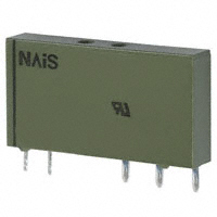
THE SLIM POWER RELAY
PE RELAYS (APE)
FEATURES
1. 5 mm .197 inch width allows high
density mounting.
Space saved with 5 mm .197 inch slim
type with 28 mm 1.102 inch length.
Allows high density mounting and
enables making of compact devices.
2. Satisfies insulation distance
standard (VDE0700: household
devices).
Maintains clearance and creepage
distance of 8 mm.
3. High capacity of 6A.
Supports 6A 250 V AC nominal switching
capacity (resistive load) and high
capacity loads.
4. 1 Form A and 1 Form C contact
arrangements available.
1 Form A and 1 Form C contact
arrangements and a rich variation let you
select the number of poles needed for
your application.
(Please inquire regarding 1 Form B.)
5. 4,000 V high breakdown voltage and
6,000 V high surge breakdown voltage.
Controller malfunction due to surges and
noise is prevented thanks to breakdown
voltage of 4,000 Vrms for 1 min. between
contacts and coil, and 6,000 V surge
breakdown voltage between contacts and
coil.
Product is discontinued.
6. Sealed construction allows
automatic washing.
7. Complies with all safety standards.
Complies with Electrical Appliance and
Material Safety Law. UL, C-UL, VDE,
SEMKO and SEV certified.
TYPICAL APPLICATIONS
1. Interface relays for programmable
controllers
2. Output relays for measuring
equipment, timers, counters and
temperature controllers
3. Industrial equipment, office
equipment
4. House-hold appliances for Europe
ORDERING INFORMATION
APE
0
Contact arrangement
1: 1 Form A
3: 1 Form C
Contact type
0: Single contact
Contact material
0: Standard contact
1: Standard contact/Au-plated
Coil voltage (DC)
4H: 4.5 V 05: 5 V 06: 6 V 12: 12 V 18: 18 V 24: 24 V 48: 48 V 60: 60 V
Note: UL/C-UL/VDE/SEMKO approved type is standard.
ds_61C12_0000_en_pe: 130709D
1
�PE (APE)
Discontinued as of May 31, 2010
TYPES
Contact arrangement
Nominal coil voltage
4.5V DC
5V DC
6V DC
12V DC
18V DC
24V DC
48V DC
60V DC
4.5V DC
5V DC
6V DC
12V DC
18V DC
24V DC
48V DC
60V DC
4.5V DC
5V DC
6V DC
12V DC
18V DC
24V DC
48V DC
60V DC
4.5V DC
5V DC
6V DC
12V DC
18V DC
24V DC
48V DC
60V DC
1 Form A
(without Au-plated)
1 Form A
(with Au-plated)
1 Form C
(without Au-plated)
1 Form C
(with Au-plated)
Part No.
APE1004H
APE10005
APE10006
APE10012
APE10018
APE10024
APE10048
APE10060
APE1014H
APE10105
APE10106
APE10112
APE10118
APE10124
APE10148
APE10160
APE3004H
APE30005
APE30006
APE30012
APE30018
APE30024
APE30048
APE30060
APE3014H
APE30105
APE30106
APE30112
APE30118
APE30124
APE30148
APE30160
Standard packing: Carton: 20 pcs.; Case: 1,000 pcs.
RATING
1. Coil data
Nominal coil
voltage
4.5V DC
5V DC
6V DC
12V DC
18V DC
24V DC
48V DC
60V DC
2
Pick-up voltage
(at 20°C 68°F)
66%V or less of
nominal voltage
(Initial)
Drop-out voltage
(at 20°C 68°F)
5%V or more of
nominal voltage
(Initial)
Nominal operating
current
[±10%] (at 20°C 68°F)
38mA
34mA
28mA
14mA
9mA
7mA
5mA
3mA
Coil resistance
[±10%] (at 20°C 68°F)
119Ω
148Ω
212Ω
847Ω
1,906Ω
3,388Ω
10,618Ω
20,572Ω
Nominal operating
power
170mW
Max. allowable voltage
(at 20°C 68°F)
120%V of
nominal voltage
217mW
175mW
ds_61C12_0000_en_pe: 130709D
�PE (APE)
Discontinued as of May 31, 2010
2. Specifications
Characteristics
Item
Arrangement
Initial contact resistance, max.
Contact material
Nominal switching capacity (resistive load)
Max. switching power (resistive load)
Max. switching voltage
Max. switching current
Nominal operating power
Min. switching capacity (Reference value)*1
Contact
Rating
Breakdown voltage
(Initial)
Between open contacts
Between contact and coil
Specifications
1 Form A, 1 Form C
Max. 100 mΩ (By voltage drop 6 V DC 1A)
Max. 30 mΩ (By voltage drop 6 V DC 1A)
AgSnO2 type
Au-plated AgSnO2 type
6 A 250 V AC
1,500 VA
250V AC
6 A (AC)
170 mW (5 to 24 V DC), 217 mW (48 V DC), 175mW (60 V DC)
100 mA 5 V DC (without Au-plated), 1 mA 1 V DC (with Au-plated)
Min. 1,000MΩ (at 500V DC)
Measurement at same location as “Initial breakdown voltage” section.
1,000 Vrms for 1 min. (Detection current: 10 mA)
4,000 Vrms for 1 min. (Detection current: 10 mA)
Surge breakdown
voltage*2
Between contact and coil
6,000 V (initial)
Insulation resistance (Initial)
Electrical
characteristics
Max. 30°C
(By resistive method, nominal voltage applied to the coil; contact carrying current: 6A.)
Max. 8 ms (approx. 5 ms)
(Nominal voltage applied to the coil, excluding contact bounce time.)
Max. 4 ms (approx. 2.5 ms)
(Nominal voltage applied to the coil, excluding contact bounce time.) (without diode)
1 Form C: Min. 49 m/s2; 1 Form A: Min. 98 m/s2
(Half-wave pulse of sine wave: 11 ms; detection time: 10μs.)
Min. 980 m/s2 (Half-wave pulse of sine wave: 6 ms.)
10 to 55 Hz at double amplitude of 1 mm (Detection time: 10μs.)
10 to 55 Hz at double amplitude of 1.5 mm
Min. 5×10⁶ (at 180 cpm)
N.O.: Min. 5×10⁴, N.C.: Min. 3×10⁴ (at 6 cpm) (at rated load)
Ambient temperature: –40°C to +85°C –40°F to +185°F;
Humidity: 5 to 85% R.H. (Not freezing and condensing at low temperature)
6 cpm
Approx. 4 g .14 oz
Temperature rise (at 20°C 68°F)
Operate time (at 20°C 68°F)
Release time (at 20°C 68°F)
Shock resistance
Mechanical
characteristics
Vibration resistance
Functional
Destructive
Functional
Destructive
Mechanical
Electrical
Expected life
Conditions for operation, transport and storage*3
Conditions
Max. operating speed (at rated load)
Unit weight
Notes:
*1 This value can change due to the switching frequency, environmental conditions, and desired reliability level, therefore it is recommended to check this with
the actual load
*2 Wave is standard shock voltage of ±1.2×50μs according to JEC-212-1981
*3 Refer to “6. Usage, Storage and Transport Conditions” in AMBIENT ENVIRONMENT section in Relay Technical Information.
REFERENCE DATA
2. Coil temperature rise
3. Ambient temperature characteristics
Tested sample: APE30012
Measured portion: Inside the coil
Ambient temperature: 28°C 82°F
Tested sample: APE30012, 6 pcs.
90
Load Limit Curve
Temperature rise, °C
AC resistive load
200
Voltage [V]
6A
0A
80
400
300
100
DC resistive load
70
60
ds_61C12_0000_en_pe: 130709D
5
30
20
50
0
20
-10
30
0
Pick-up voltage
40
-40 -20
40
-20
60
85
Drop-out
voltage
Ambient
temperature, °C
-30
10
1
Current [A]
40
10
20
10
0.1
Rate of
change, %
1. Max. switching capacity
100
110
120
130
Coil applied voltage, %V
-40
3
�PE (APE)
Discontinued as of May 31, 2010
DIMENSIONS (Unit: mm inch)
1. 1 Form A type
PC board pattern (Bottom view)
15.0max.
.591max.
0.5
.020
3.5
.138
0.4 +0.2
-0.1
.016 +.008
Ð.004
1.2
.047
2-0.5
2-.020
3.78
.149
21.42
.843
28.0max.
1.102max.
2-1.0
2-.039
1.9
.075
5.04
.198
0.4 +0.2
Ð0.1
.016 +.008
-.004
1.2
.047
5.0max.
.197max.
3.78
.149
2-1
.
2-. 3 dia
05 .
1d
ia .
2-1
.
2-.0 0 dia.
39
dia
.
External dimensions
21.42
.843
5.04
.198
1.2
.047
1.9
.075
Tolerance: ±0.1 ±.004
Schematic (Bottom view)
General tolerance: ±0.3 ±.012
COM
Coil
NO
2. 1 Form C type
PC board pattern (Bottom view)
15.0max.
.591max.
0.5
.020
3.5
.138
0.4 +0.2
-0.1
.016 +.008
-.004
1.2
.047
2-0.5
2-.020
3.78
.149
3-1.0
3-.039
1.9
.075
21.42 5.04 5.04
.843 .198 .198
28.0max.
1.102max.
0.4 +0.2
-0.1
.016 +.008
-.004
1.2
.047
5.0max.
.197max.
3-1
.
3-. 3 dia
05 .
1d
ia.
2-1
.
2-.0 0 dia.
39
dia
.
External dimensions
1.2
.047
5.04 5.04
.198 .198
21.42
.843
3.78
.149
1.9
.075
Tolerance: ±0.1 ±.004
Schematic (Bottom view)
General tolerance: ±0.3 ±.012
Coil
NC
COM
NO
PE RELAY SOCKET
1. Dimensions
2. Pin Layout
3. Handling
Hold-down clip
Hold-down clip open
7-
56
51
1.3
Grid: 1.25 ... 1.27
Relay
+
-
2.54
1.84
6.28
3.39
LED
5.8
Slide
37
29
(+,-) Polarity of LED
Bottom view
0.9
0.5
6.28
0.3
Push down the hold-down clip in order
to cast the relay.
5
37
Specifications
LED
Pins rating
nominal voltage
24 V DC
nominal current
appr. 4.2 mA
diameter
3 mm
color
green*
see above
*other LED-colors on request
PE1-PS-GD
4
Socket incorporates LED-indication, hold-down clip and an integrated casting mechanism;
PCB-mounting.
ds_61C12_0000_en_pe: 130709D
�PE (APE)
Discontinued as of May 31, 2010
NOTES
1. Cleaning
For automatic cleaning, the boiling
method is recommended. Avoid
ultrasonic cleaning which subjects the
relays to high frequency vibrations, which
may cause the contacts to stick.
It is recommended that a fluorinated
hydrocarbon or other alcoholic solvents
be used.
2. Soldering
The automatic soldering shall be
performed under following condition.
1) Preheating
Temperature: Max. 120°C 248°F
Time: Max. 120s
2) Soldering
Temperature: 260°C±5°C 500°F±41°F
Time: Max. 6s
3. Coil operating power
Pure DC current should be applied to the
coil. The wave form should be
rectangular. If it includes ripple, the ripple
factor should be less than 5%.
However, check it with the actual circuit
since the characteristics may be slightly
different.
4. Relay mounting
If, after mounting on PC boards, the
relays are to be subjected to vibration
during operation, use other means
besides soldering to secure the relays to
the PC board.
For Cautions for Use, see Relay Technical Information.
ds_61C12_0000_en_pe: 130709D
5
�


 工商网监
湘ICP备2023018690号
工商网监
湘ICP备2023018690号
