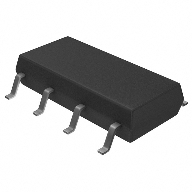
Miniature SOP8-pin type
of 60V/350V/400V
load voltage
9.37
.369
4.4
.173
2.1
.083
mm inch
1
8
2
7
3
6
4
5
RoHS compliant
GU SOP 2 Form A
(AQW21❍S)
FEATURES
TYPICAL APPLICATIONS
1. 2 channels in miniature SOP8-pin
design
The device comes in a super-miniature
SO package measuring (W) 4.4 × (L)
9.37 × (H) 2.1 mm (W) .173× (L) .369×
(H) .083 inch —approx. 38% of the
volume and 66% of the footprint size of
DIP8-pin type.
2. Controls low-level analog signals
PhotoMOS feature extremely low closedcircuit offset voltage to enable control of
low-level analog signals without
distortion.
3. Low-level off state leakage current
of max. 1 μA
• Measuring instruments
• Data communications
• Computers
• Industrial robots
TYPES
Output rating*
AC/DC
dual use
Load
voltage
Load
current
60V
400mA
350V
100mA
400V
80mA
Part No.
Package
SOP8-pin
Packing quantity
Tape and reel packing style
Picked from the
Picked from the
1/2/3/4-pin side
5/6/7/8-pin side
Tube packing style
AQW212S
AQW212SX
AQW212SZ
AQW210S
AQW210SX
AQW210SZ
AQW214S
AQW214SX
AQW214SZ
Tube
Tape and reel
1 tube contains:
50 pcs.
1 batch contains:
1,000 pcs.
1,000 pcs.
* Indicate the peak AC and DC values.
Note: The packing style indicator “X” or “Z” are not marked on the device.
RATING
1. Absolute maximum ratings (Ambient temperature: 25°C 77°F)
Input
Output
Item
LED forward current
LED reverse voltage
Peak forward current
Power dissipation
Load voltage (peak AC)
Symbol
IF
VR
IFP
Pin
VL
AQW212S
Continuous load current
Peak load current
Power dissipation
Total power dissipation
I/O isolation voltage
Ambient temperature
Operating
Storage
AQW214S
60 V
AQW210S
50 mA
5V
1A
75 mW
350 V
IL
0.4 A (0.5 A)
0.1 A (0.13 A)
0.08 A (0.1 A)
Ipeak
Pout
PT
Viso
Topr
Tstg
1.5 A
f = 100 Hz, Duty factor = 0.1%
400 V
0.3 A
0.24 A
600 mW
650 mW
1,500 Vrms
–40 to +85°C –40 to +185°F
–40 to +100°C –40 to +212°F
–1–
Remarks
Peak AC, DC
( ): in case of using only 1 channel
A connection: 100 ms (1 shot), VL = DC
(Non-icing at low temperatures)
ASCTB141E 201703-T
�GU SOP 2 Form A (AQW21❍S)
2. Electrical characteristics (Ambient temperature: 25°C 77°F)
Item
Symbol
Typical
Maximum
Minimum
Typical
Typical
Maximum
LED operate current
Input
LED turn off current
LED dropout voltage
AQW212S
IFon
IFoff
VF
Typical
On resistance
Ron
Maximum
Output
Off state leakage current
Maximum
Typical
Maximum
Typical
Maximum
Typical
Maximum
Minimum
Turn on time*
Turn off time*
Transfer
characteristics
I/O capacitance
Initial I/O isolation resistance
AQW210S
AQW214S
0.9 mA
3 mA
0.4 mA
0.8 mA
1.25 V (1.14 V at IF = 5 mA)
1.5 V
0.83 Ω
16 Ω
30 Ω
2.5 Ω
35 Ω
50 Ω
0.65 ms
0.23 ms
Condition
IL = Max.
IL = Max.
IF = 50 mA
IF = 5 mA
IL = Max.
Within 1 s
IF = 0 mA
VL = Max.
1 μA
ILeak
Ton
2 ms
0.08 ms
Toff
0.21 ms
IF = 5 mA
IL = Max.
0.5 ms
0.04 ms
IF = 5 mA
IL = Max.
0.2 ms
0.8 pF
Ciso
f = 1 MHz
VB = 0 V
1.5 pF
1,000 MΩ
Riso
500 V DC
*Turn on/Turn off time
Input
90%
3. Recommended operating conditions (Ambient temperature: 25°C 77°F)
Please use under recommended operating conditions to obtain expected characteristics.
Item
AQW212S
AQW210S
AQW214S
Symbol
LED current
Load voltage (Peak AC)
IF
VL
Continuous load current
IL
Load voltage (Peak AC)
VL
Continuous load current
IL
Load voltage (Peak AC)
VL
Continuous load current
IL
Number of
used channels
1ch
2ch
Min.
Max.
Unit
5
—
30
48
mA
V
0.5
0.4
280
—
—
1ch
2ch
—
1ch
2ch
Toff
Ton
V
A
V
0.1
0.08
—
10%
A
0.13
0.1
320
—
Output
A
■ These products are not designed for automotive use.
If you are considering to use these products for automotive applications, please contact your local Panasonic Corporation
technical representative.
REFERENCE DATA
1.-(1) Load current vs. ambient temperature
characteristics
1.-(2) Load current vs. ambient temperature
characteristics
2.-(1) On resistance vs. ambient temperature
characteristics
Allowable ambient temperature: –40 to +85°C
–40 to +185°F
When using 2 channels
Allowable ambient temperature: –40 to +85°C
–40 to +185°F
When using 2 channels
Measured portion: between terminals 5 and 6, 7 and 8;
LED current: 5 mA; Load voltage: Max. (DC);
Continuous load current: Max. (DC)
1.0
5
0.4
AQW212S
100
80
On resistance, Ω
Load current, A
0.6
Load current, mA
120
0.8
AQW210S
AQW214S
60
4
3
2
40
AQW212S
0.2
1
20
0
–40 –20
0
20
40
60 8085 100
Ambient temperature, °C
0
–40 –20
0
20
40
60
8085 100
Ambient temperature, °C
–2–
0
–40
–20
0
20
40
60
8085
Ambient temperature, °C
ASCTB141E 201703-T
�GU SOP 2 Form A (AQW21❍S)
2.-(2) On resistance vs. ambient temperature
characteristics
3. Turn on time vs. ambient temperature
characteristics
4. Turn off time vs. ambient temperature
characteristics
Measured portion: between terminals 5 and 6, 7 and 8;
LED current: 5 mA; Load voltage: Max. (DC);
Continuous load current: Max. (DC)
LED current: 5 mA;
Load voltage: Max. (DC);
Continuous load current: Max. (DC)
LED current: 5 mA;
Load voltage: Max. (DC);
Continuous load current: Max. (DC)
50
1.4
0.4
30
AQW210S
20
1.0
0.8
AQW210S
0.6
Turn off time, ms
1.2
AQW214S
40
Turn on time, ms
On resistance, Ω
AQW212S
0.3
0.2
AQW214S
0.4
AQW212S
AQW214S
0.1
10
0.2
0
–40
–20
0
20
40
60
0
8085
AQW210S
–40
–20
0
20
40
60
0
8085
–40
–20
Ambient temperature, °C
Ambient temperature, °C
0
20
40
60
5. LED operate current vs. ambient
temperature characteristics
6. LED turn off current vs. ambient temperature
characteristics
7. LED dropout voltage vs. ambient
temperature characteristics
Sample: All types; Load voltage: Max. (DC);
Continuous load current: Max. (DC)
Sample: All types; Load voltage: Max. (DC);
Continuous load current: Max. (DC)
Sample: All types;
LED current: 5 to 50 mA
5
4
3
2
1.5
LED dropout voltage, V
LED turn off current, mA
LED operate current, mA
5
8085
Ambient temperature, °C
4
3
2
1.4
1.3
50mA
1.2
30mA
20mA
1.1
1
1
0
0
10mA
5mA
1.0
–40
–20
0
20
40
60
8085
–40
–20
0
20
40
60
0
80 85
–40
–20
Ambient temperature, °C
Ambient temperature, °C
0
20
40
60 8085
Ambient temperature, °C
8.-(2) Current vs. voltage characteristics of
output at MOS portion
9. Off state leakage current vs. load voltage
characteristics
Measured portion: between terminals 5 and 6, 7 and 8;
Ambient temperature: 25°C 77°F
Measured portion: between terminals 5 and 6, 7 and 8;
Ambient temperature: 25°C 77°F
Measured portion: between terminals 5 and 6, 7 and 8;
Ambient temperature: 25°C 77°F
140
150
100
80
60
40
20
-5 -4 -3 -2 -1
0.4
AQW212S
0.3
AQW210S
AQW214S
Current, mA
Current, A
0.5
0.2
0.1
-1.0 -0.8 -0.6 -0.4 -0.2
0.2 0.4 0.6 0.8 1.0
-0.1 Voltage, V
1
-20
-40
-60
-80
-100
-120
-140
-0.2
-0.3
-0.4
-0.5
2
3 4 5
Voltage, V
Off state leakage current, A
8.-(1) Current vs. voltage characteristics of
output at MOS portion
10–3
10–6
10–9
AQW212S
AQW214S
AQW210S
10–12
0
20
40
60
80
100
Load voltage, V
10. Turn on time vs. LED forward current
characteristics
11. Turn off time vs. LED forward current
characteristics
12. Output capacitance vs. applied voltage
characteristics
Measured portion: between terminals 5 and 6, 7 and 8;
Load voltage: Max. (DC); Continuous load current:
Max. (DC); Ambient temperature: 25°C 77°F
Measured portion: between terminals 5 and 6, 7 and 8;
Load voltage: Max. (DC); Continuous load current:
Max. (DC); Ambient temperature: 25°C 77°F
Measured portion: between terminals 5 and 6, 7 and 8;
Frequency: 1 MHz;
Ambient temperature: 25°C 77°F
1.4
AQW212S
0.8
0.6
90
AQW214S
0.4
0.10
Output capacitance, pF
1.0
100
0.12
Turn off time, ms
Turn on time, ms
1.2
0.14
AQW210S
AQW212S
0.08
0.06
AQW214S
0.04
80
70
60
50
40
30
AQW212S
AQW210S
20
0.2
0.02
0
0
10
20
30
40
50
LED forward current, mA
60
10
10
20
30
40
50
LED forward current, mA
–3–
60
0
0
AQW210S, AQW214S
10
20
30
40
50
Applied voltage, V
ASCTB141E 201703-T
��