Automation Controls Catalog
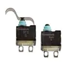
SUBMINIATURE,
LONG STROKE
SEALED SWITCHES
New
8.3
(Unit: mm)
5.3
7.85
8.3
5.3
Terminal type
13.55
Wire leads type
RoHS compliant
TURQUOISE STROKE
MINI SWITCHES
FEATURES
TYPICAL APPLICATIONS
• Miniaturization achieved with
changing from 1 Form C to 1 Form A
or 1 Form B contacts.
(For the terminal type, volume has
been cut 45% compared to our
previous product.)
• Lever installation possible while
being miniature.
Operation possible in various moving
parts such as metal cams.
• Contact pressure does not depend
on the operation stroke.
• High contact reliability to support
low level switching loads.
• Highly effective sealing for resistance against adverse environments.
(IP67)
• Silent operation with sliding contact.
• Automobiles (detection of door
opening and closing, shift lever
position, etc.)
• Household appliances (vacuum
cleaners, air conditioners, washing
machines, etc.)
ORDERING INFORMATION
ASQM1
Mounting
1: Without boss type (wire leads type only)
6: Right 2 boss type (terminal type only)
7: Left 2 boss type (terminal type only)
Terminal
4: Terminal type (Solder terminal)
6: Wire leads type
Contact form
2: Normally Closed type (NC)
3: Normally Open type (NO)
Actuator
0: Pin plunger
8: Simulated roller lever
Note: Not every combination is available. Please refer to the following table, “PRODUCT TYPES”.
PRODUCT TYPES
1. Terminal type (solder terminal)
Actuator
Pin plunger
Simulated roller lever
Carton: 1,000 pcs.
Right 2 boss type
NC type
ASQM16420
ASQM16428
Left 2 boss type
NO type
ASQM16430
ASQM16438
NC type
ASQM17420
ASQM17428
NO type
ASQM17430
ASQM17438
2. Wire leads type
Actuator
Pin plunger
Simulated roller lever
2013.11
industrial.panasonic.com/ac/e/
Carton: 240 pcs.
NC type
ASQM11620
ASQM11628
NO type
ASQM11630
ASQM11638
–1–
© Panasonic Corporation 2013
AECTB55E 201311-T
�Turquoise Stroke mini Switch
RATING
1. Rating
1 mA, 5 V DC to 50 mA, 16 V DC
2. Operation environment and conditions
Item
Ambient and storage temperature
Allowable operating speed
Max. operating cycle rate
Specifications
–40°C to +85°C (no freezing and condensing)
30 to 500 mm/sec.
120 cpm
Note: When switching at low and high speeds or under vibration, or in high-temperature, high-humidity environments, life and performance may be reduced significantly
depending on the load capacity. Please consult us.
3. Electrical characteristics
Item
Withstand voltage (Initial)
Insulation resistance (Initial)
Contact resistance (Initial)
Specifications
Between non-continuous terminals: 500 Vrms, Between each terminal and other exposed metal parts: 1,500 Vrms,
Between each terminal and ground: 1,500 Vrms (at detection current of 1 mA)
Min. 100 MΩ (at 500 V DC insulation resistance meter) (Locations measured same as withstand voltage.)
Max. 500 mΩ (By voltage drop 50 mA 6 to 8 V DC)
4. Characteristics
Item
5 V DC 1 mA (resistive load)
Electrical
switching life
Min. 3 × 10⁵
12 V DC 50 mA (resistive load)
Min. 2 × 10⁵
16 V DC 50 mA (resistive load)
Min. 1.5 × 10⁵
Vibration resistance
(malfunction vibration resistance)
Shock resistance
(malfunction shock resistance)
Terminal strength
Heat resistance
Cold resistance
Humidity resistance
Water resistance
Specifications
Switching frequency: 20 times/min.
Conduction ratio: 1:1
Plunger operation speed: 100 mm/s
Plunger switching position: Free Position (F.P.) to Total Travel Position (T.T.P.)
Single amplitude: 0.75 mm
Amplitude of vibration: 10 to 55 Hz (4 minutes cycle)
Direction and time: 30 minutes each in X, Y and Z directions
Amplitude of vibration: 5 to 200 Hz (10 minutes cycle)
Acceleration: 43.1 m/s2
Direction and time: 30 minutes each in X, Y and Z directions
Shock value: 980 m/s2
Direction and time: 5 times each in X, Y and Z directions
6 N min. (each direction) *Terminal deformation possible.
85°C 500 hours
–40°C 500 hours
40°C 95% RH 500 hours
IP67 (Wire leads type)
Notes: As long as there are no particular designations, the following conditions apply to the test environment.
• Ambient temperature: 5 to 35°C
• Relative humidity: 25 to 85% RH
• Air pressure: 86 to 106 kPa
5. Protective structure
1) JIS C0920 (water-resistance experiments for electrical
machines and protection rating against incursion of solid
substances): Immersion protected (Note 1)
2) IEC 60529 (rating for outer shell protection): IP67 (Immersion
protected) (Note 1)
except metal terminal part (See below drawing)
3) JIS D0203 (method for testing moisture resistance and water
resistance in automotive components): Equivalent of D2 (Note 2)
Note 1) A concrete testing method is to check for any adverse effect on the structure
after leaving it submerged for 30 minutes under 1 m of water (with
temperature difference between water and switch no larger than 5°C).
Note 2) A concrete testing method is to check for any adverse effect on the structure
after leaving it submerged for 10 minutes under 10 cm water (with
temperature difference between water and switch no larger than 30°C).
Metal terminal part
Panasonic Corporation Automation Controls Buisiness Division
industrial.panasonic.com/ac/e/
–2–
© Panasonic Corporation 2013
AECTB55E 201311-T
�Turquoise Stroke mini Switch
6. Operating characteristics
Characteristics
Operating Force (O.F.) max.
Total Travel Force (T.F.) max. (Reference value)
Terminal type
Free Position (F.P.) max.
Wire leads type
Pin plunge
Terminal type
Operating Position (O.P.)
Wire leads type
Terminal type
Release Position (R.P.)
Wire leads type
Terminal type
Over Travel (O.T.) min.
Wire leads type
Terminal type
Wire leads type
Total Travel Position (T.T.P.)
(Reference value)
Simulated roller lever
1.2N
(3.0N)
7.7mm
14.45mm
1.5N
(2.8N)
13.4mm
20.15mm
Initial: 7.1±0.25mm
After test: 7.1±0.3mm
Initial: 13.75±0.35mm
After test: 13.75±0.4mm
Initial: 7.15±0.3mm
After test: 7.15±0.35mm
Initial: 13.8±0.4mm
After test: 13.8±0.45mm
Initial: 1.75mm
After test: 1.70mm
Initial: 1.65mm
After test: 1.60mm
(5.1mm)
(11.75mm)
Initial: 10.75±0.6mm
After test: 10.75±0.7mm
Initial: 17.4±0.7mm
After test: 17.4±0.8mm
Initial: 11.05±0.7mm
After test: 11.05±0.8mm
Initial: 17.7±0.8mm
After test: 17.7±0.9mm
Initial: 2.25mm
After test: 2.15mm
Initial: 2.15mm
After test: 2.05mm
(7.9mm)
(14.55mm)
Note: The above indicates the characteristics when operating the actuator from the vertical direction.
DATA
Applicable current range (Reference)
50mA
Applicable range
1mA
0
DC
5V
16V
DIMENSIONS
The CAD data of the products with a
CAD Data
mark can be downloaded from: http://industrial.panasonic.com/ac/e/
mm General tolerance: ±0.25
1. Terminal type (Solder terminal), Right 2 boss type, Pin plunger
CAD Data
2.6±0.05
Operating Force (O.F.) max.
1.2N
Total Travel Force (T.F.) max.
(Reference value)
(3.0N)
Free Position (F.P.) max.
7.7mm
Operating Position (O.P.)
1.9 dia.
4.0
.
1.8
0.6
Over Travel (O.T.) min.
Total Travel Position (T.T.P.)
(Reference value)
(5.1mm)
3.2
5.0±0.1
dia
2.6±0.05
2.2
3.85
.
dia
4.0
T.T.P. (5.1)
3.35
2.2
3.6
F.P. 7.7 max.
R.P. 7.15±0.3
O.P. 7.1±0.25
Release Position (R.P.)
Initial: 7.1±0.25mm
After test: 7.1±0.3mm
Initial: 7.15±0.3mm
After test: 7.15±0.35mm
Initial: 1.75mm
After test: 1.70mm
1.2
2.0
4.08±0.15
8.3
0.4
5.3±0.15 2.0
Panasonic Corporation Automation Controls Buisiness Division
industrial.panasonic.com/ac/e/
–3–
© Panasonic Corporation 2013
AECTB55E 201311-T
�Turquoise Stroke mini Switch
mm General tolerance: ±0.25
2. Terminal type (Solder terminal), Left 2 boss type, Pin plunger
CAD Data
2.6±0.05
Total Travel Force (T.F.) max.
(Reference value)
(3.0N)
Free Position (F.P.) max.
7.7mm
dia
Total Travel Position (T.T.P.)
(Reference value)
(5.1mm)
Operating Force (O.F.) max.
1.5N
Total Travel Force (T.F.) max.
(Reference value)
(2.8N)
3.2
5.0±0.1
1.8
0.6
Over Travel (O.T.) min.
Initial: 7.1±0.25mm
After test: 7.1±0.3mm
Initial: 7.15±0.3mm
After test: 7.15±0.35mm
Initial: 1.75mm
After test: 1.70mm
4.0
2.2
.
2.6±0.05
.
dia
3.6
T.T.P. (5.1)
3.35
2.2
3.85
Release Position (R.P.)
R.P. 7.15±0.3
O.P. 7.1±0.25
F.P. 7.7 max.
1.2N
Operating Position (O.P.)
1.9 dia.
4.0
Operating Force (O.F.) max.
1.2
2.0
2.0
4.08±0.15
8.3
0.4
5.3±0.15
3. Terminal type (Solder terminal), Right 2 boss type, Simulated roller lever
CAD Data
2.6±0.05
Free Position (F.P.) max.
R2
3.3
.0
Operating Position (O.P.)
(8.6)
2.2
.
Total Travel Position (T.T.P.)
(Reference value)
(7.9mm)
Operating Force (O.F.) max.
1.5N
Total Travel Force (T.F.) max.
(Reference value)
(2.8N)
3.2
5.0±0.1
1.8
0.6
2.6±0.05
dia
.
dia
3.85
2.2
Initial: 10.75±0.6mm
After test: 10.75±0.7mm
Initial: 11.05±0.7mm
After test: 11.05±0.8mm
Initial: 2.25mm
After test: 2.15mm
4.0
3.35
T.T.P. (7.9)
Over Travel (O.T.) min.
3.6
F.P. 13.4 max.
R.P. 11.05±0.7
O.P. 10.75±0.6
Release Position (R.P.)
13.4mm
1.2
2.0
0.4
5.3±0.15
4.08±0.15
8.3
2.0
4. Terminal type (Solder terminal), Left 2 boss type, Simulated roller lever
CAD Data
Free Position (F.P.) max.
3.3
.0
R2
2.6±0.05
Operating Position (O.P.)
(8.6)
dia
2.
.
1.8
0.6
(7.9mm)
3.2
5.0±0.1
Total Travel Position (T.T.P.)
(Reference value)
2.6±0.05
.
ia
2d
3.85
2.2
Initial: 10.75±0.6mm
After test: 10.75±0.7mm
Initial: 11.05±0.7mm
After test: 11.05±0.8mm
Initial: 2.25mm
After test: 2.15mm
4.0
T.T.P. (7.9)
3.35
Over Travel (O.T.) min.
3.6
F.P. 13.4 max.
R.P. 11.05±0.7
O.P. 10.75±0.6
Release Position (R.P.)
13.4mm
1.2
2.0
0.4
4.08±0.15
8.3
2.0
5.3±0.15
Panasonic Corporation Automation Controls Buisiness Division
industrial.panasonic.com/ac/e/
–4–
© Panasonic Corporation 2013
AECTB55E 201311-T
�Turquoise Stroke mini Switch
mm General tolerance: ±0.25
5. Wire leads type, Pin plunger
CAD Data
Operating Force (O.F.) max.
1.2N
Total Travel Force (T.F.) max.
(Reference value)
(3.0N)
Free Position (F.P.) max.
8.5
5.3±0.15
8.3
14.45mm
Operating Position (O.P.)
1.9 dia.
Over Travel (O.T.) min.
0.9
T.T.P. (11.75)
.0
5
(10.5)
8.3±0.1
(Boss-Hole)
R3
F.P. 14.45 max.
R.P. 13.8±0.4
O.P. 13.75±0.35
Release Position (R.P.)
Initial: 13.75±0.35mm
After test: 13.75±0.4mm
Initial: 13.8±0.4mm
After test: 13.8±0.45mm
Initial: 1.65mm
After test: 1.60mm
Total Travel Position (T.T.P.)
(Reference value)
(11.75mm)
Operating Force (O.F.) max.
1.5N
Total Travel Force (T.F.) max.
(Reference value)
(2.8N)
3.0
6.1
+0.1
−0
2.1
dia.
+0
C
0.
45
3.0 −0.1
300±10
Sealing compound
climbing up the
wire leads: 5 max.
Burge of the
sealing compound:
2 max.
3.2
5±2
5.5±0.15
12.9
COM
NO/NC
6. Wire leads type, Simulated roller lever
CAD Data
.0
R2
8.5
5.3±0.15
3.3
(3.7)
Free Position (F.P.) max.
20.15mm
Operating Position (O.P.)
Release Position (R.P.)
Over Travel (O.T.) min.
T.T.P. (14.55)
Total Travel Position (T.T.P.)
(Reference value)
0.9
(14.55mm)
.0
5
(10.5)
8.3±0.1
(Boss-Hole)
R3
F.P. 20.15 max.
R.P. 17.7±0.8
O.P. 17.4±0.7
8.3
Initial: 17.4±0.7mm
After test: 17.4±0.8mm
Initial: 17.7±0.8mm
After test: 17.7±0.9mm
Initial: 2.15mm
After test: 2.05mm
+0
dia.
C
0.
45
3.0 −0.1
3.0
6.1
+0.1
−0
2.1
300±10
COM
5.5±0.15
5±2
Sealing compound
climbing up the
wire leads: 5 max.
Burge of the
sealing compound:
2 max.
3.2
NO/NC
12.9
CAUTIONS FOR USE
1. Soldering conditions
• The application of excessive heat upon
the switch when soldering can cause
degradation of switch operation.
Therefore, be sure to keep within the
conditions given below.
• Manual soldering: Use soldering irons
(max. 350°C, within 3 seconds) capable
of temperature adjustment. This is to
prevent deterioration due to soldering
heat. Care should be taken not to apply
force to the terminals during soldering.
(More than one second interval is
required to apply heat at each terminal.)
2. Mounting
• To secure the wire leads type switch,
please use M3 small screws on a flat
surface and tighten using a maximum
torque of 0.29 N·m.
Be sure to verify the quality under actual
conditions of use because the switch
plastic might be deformed according to
that the kind of the screw (size of screw
head etc.), the diameter of the washer
and the presence of washer. And use of
adhesive lock is recommended to prevent
loosening of the screws. When using an
adhesive, care should be taken not to
invade the adhesive into the switches.
Panasonic Corporation Automation Controls Buisiness Division
industrial.panasonic.com/ac/e/
–5–
• Be sure to maintain adequate insulating
clearance between each terminal and
ground.
• The positioning of the switch should be
such that direct force is not applied to the
plunger or actuator in its free position.
The operating force to the plunger should
only be applied in a perpendicular
direction.
• Although it is possible to directly
operate the pin plunger type from the
lateral direction, please consult us if
doing so.
• After mounting please make sure no
pulling load will be applied to the switch
terminals.
© Panasonic Corporation 2013
AECTB55E 201311-T
�Turquoise Stroke mini Switch
3. Cautions regarding the circuit
• In order to prevent malfunction in set
devices caused by bounce and chattering
during the ON-OFF switch operation,
please verify the validity of the circuit
under actual operating conditions and
temperature range.
• When switching inductive loads (relays,
solenoids, buzzers, etc.), an arc
absorbing circuit is recommended to
protect the contacts.
4. Please verify under actual
conditions.
• Please be sure to conduct quality
verification under actual operating
conditions in order to increase reliability
during actual use.
5. Switch selection
• Please make your selection so that
there will be no problems even if the
operating characteristics vary up to ±20%
from the standard values.
7. Operation environment
• Although continuous operation of the
switch is possible within the range of
ambient temperature (humidity), as the
humidity range differs depending on the
ambient temperature, the humidity range
indicated below should be used.
Continuous use near the limit of the
range should be avoided.
This temperature-humidity range does
not guarantee permanent performance.
Humidity, %R.H.
95
Acceptable range
50
(Avoid freezing when (Avoid
used at temperatures condensation when
lower than 0°C)
used at temperatures
higher than 0°C)
5
–40
0
+40
Temperature, °C
+85
6. Oil-proof and chemical-proof
characteristics
• The rubber cap swells when exposed to
oil and chemicals. The extent of swelling
will vary widely depending on the type
and amount of oil and chemicals.
Check with the actual oil or chemicals
used. In particular, be aware that solvents
such as freon, chlorine, and toluene
cannot be used.
Please contact ..........
8. Others
• Please remember that this switch
cannot be used under water. Also,
pleased be warned that switching and
sudden temperature changes with the
presence of water droplets can cause
seepage into the unit.
• Keep away from environments where
silicon based adhesives, oil or grease are
present as faulty contacts may result
from silicon oxide. Do not use in areas
where flammable or explosive gases from
gasoline and thinner, etc., may be
present.
• When using the lever type, please be
careful not to apply unreasonable load
from the reverse or lateral directions of
operation.
• Do not exceed the total travel position
(T.T.P.) and press the actuator. This could
cause operation failure. Also, when
switching at high speed or under shock
even within the operation limit, the
working life may decrease. Therefore,
please be sure to verify the quality under
actual conditions of use.
• Please make considerations so that the
switch does not become the stopper for
the moving part.
• Please do not constantly apply a tensile
load to wire leads when fixing them.
Panasonic Corporation
Automation Controls Business Division
Head Office: 1048, Kadoma, Kadoma-shi, Osaka 571-8686, Japan
Telephone: +81-6-6908-1050
Facsimile: +81-6-6908-5781
industrial.panasonic.com/ac/e/
© Panasonic Corporation 2013
Specifications are subject to change without notice.
Panasonic Corporation Automation Controls Buisiness Division
industrial.panasonic.com/ac/e/
–6–
© Panasonic Corporation 2013
Printed in Japan.
AECTB55E 201311-T
�


 工商网监
湘ICP备2023018690号
工商网监
湘ICP备2023018690号
