For detection: Non Seal Type Switches
AV6 ( CS ) Switches
Product Catalog
2022.4
�For detection: Non Seal Type Switches
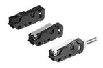
AV6 (CS) Switches
Subminiature Size Connector Integrated Type
FEATURES
Easy assembling as this switch is connector
integrated
High contact reliability by simple dust prevension
guard and Au-clad double layer contacts
Two types of contact form are available, the SPSTNC and the SPST-NO.
The lever position can be changed. the standard
lever position and the backward lever position
Protection grade: IP40
7
29.2
10
TYPICAL APPLICATIONS
Vending machine sold-out detection
Pachinko ball presence detection
Copying machine
Printer
Also for all types of equipment required for
maintenance and inspections.
(Unit: mm)
ORDERING INFORMATION (PART NO.)
AV 6
Contact form
2: SPSTNC
(Plunger color: Red)
3: SPSTNO
(Plunger color: Yellow)
Actuators
0: Pin plunger
2: Hinge lever
4: Simulated roller lever
64
Operating Force (OP)
by pin plunger, Max.
2: 0.50 N
5: 1.50 N
Lever position
Nil: Standard
Contact material
64: CuNi alloy+Auclad contact
12: Backward
5: Roller lever
Note) When ordering, please add "A" at the end of the part number.
LEVER POSITION
1) Standard
2) Backward
APPLICABLE CONNECTOR
Greatly improved assembling due to connector connection.
• �Applicable connector: XA connector produced by JST Mfg. Co., Ltd.
Contact: SXA-001T-P0.6
Housing: XAP-02V-1
Connector
Panasonic Industry Co., Ltd. Electromechanical Control Business Division
industrial.panasonic.com/ac/e/
ー1ー
Panasonic Industry Co., Ltd. 2022
AECTB60E 202204
�AV6 (CS) Switches
TYPES
Lever position: Standard
Actuator
Contact type
Operating Force
(OF) Max.
SPST-NC
SPST-NO
0.50 N
AV620264
AV630264
1.50 N
AV620564
AV630564
0.20 N
AV622264
AV632264
0.50 N
AV622564
AV632564
0.20 N
AV624264
AV634264
0.50 N
AV624564
AV634564
0.20 N
AV625264
AV635264
0.50 N
AV625564
AV635564
Operating Force
(OF) Max.
SPST-NC
SPST-NO
0.35 N
AV62221264
AV63221264
1.00 N
AV62251264
AV63251264
0.35 N
AV62421264
AV63421264
1.00 N
AV62451264
AV63451264
0.35 N
AV62521264
AV63521264
1.00 N
AV62551264
AV63551264
Contact voltage
Resistive load (cos φ ≈ 1)
Pin plunger
Hinge lever
Simulated roller lever
Roller lever
Lever position: Backward
Actuator
Hinge lever
Simulated roller lever
Roller lever
Contact type
RATING
Contact rating
Contact
CuNi alloy + Au-clad contact
30 V DC
0.1 A
5 V DC
1 mA Low-level circuit rating
Specifications
Item
Expected life
Min. 5 × 10⁵ (at 60 cpm)
Electrical (Rated load OT Max.)
Min. 2 × 10⁵ (at 20 cpm)
Between non-continuous terminals
1,000 Vrms for 1 min.
Between each terminal and other
exposed metal parts
1,500 Vrms for 1 min.
Min. 100 MΩ
Insulation resistance
Dielectric strength
Specifications
Mechanical (OT) Max.
Between each terminal and ground 1,500 Vrms for 1 min.
Contact resistance (initial)
100 mΩ max. (by voltage drop 0.1 A 6 to 8 V DC)
Value includes the resistance between the connector and the lead (#AWG28, length: 50 mm)
Viblation resistance (malfunction vibration resistance)
10 to 55 Hz at single amplitude of 0.75 mm (Contact opening: max. 1 msec)
Shock resistance (malfunction shock resistance)
Applied shock 1.50 N type: Min.300 m/s2 (Contact opening: Max. 1 msec)
0.50 N type: Min.150 m/s2 (Contact opening: Max. 1 msec)
Connector insertion force
Max. 20 N (inserted in removal direction)
Connector holding force
Min. 20 N (extracted by static load, in removal direction)
Connector removal operating times
Max. 5 times (in removal direction)
Allowable operating speed (No load)
0.1 to 1,000 mm/s (at pin plunger)
Max. operating cycle rate (No load)
300 cpm
Ambient temperature
–25 to +85°C (No freezing and condensing)
Unit weight
Approx. 2.5 g (pin plunger type)
Contact specifications Contact material
CuNi alloy + Au-clad
Protection grade
IP40
Panasonic Industry Co., Ltd. Electromechanical Control Business Division
industrial.panasonic.com/ac/e/
ー2ー
Panasonic Industry Co., Ltd. 2022
AECTB60E 202204
�AV6 (CS) Switches
Operating characteristics
1) Lever position: Standard
Actuator
Operating Force
(OF) Max.
Release Force
(RF) Min.
0.50 N
0.04 N
1.50 N
0.25 N
0.20 N
0.02 N
0.50 N
0.06 N
0.20 N
0.02 N
0.50 N
0.06 N
0.20 N
0.02 N
0.50 N
0.06 N
Operating Force
(OF) Max.
Release Force
(RF) Min.
0.35 N
0.03 N
1.00 N
0.10 N
0.35 N
0.03 N
1.00 N
0.10 N
0.35 N
0.03 N
1.00 N
0.10 N
Pin plunger
Hinge lever
Simulated roller lever
Roller lever
Pretravel
(PT) Max.
Movement
Differential
(MD) Max.
Overtravel
(OT) Min.
Operating Position
(OP)
0.6 mm
0.1 mm
0.4 mm
8.4±0.3 mm
2.6 mm
0.8 mm
1.2 mm
10.0±0.8 mm
2.6 mm
0.8 mm
1.2 mm
12.2±0.8 mm
2.6 mm
0.8 mm
1.2 mm
15.7±0.8 mm
Pretravel
(PT) Max.
Movement
Differential
(MD) Max.
Overtravel
(OT) Min.
Operating Position
(OP)
1.4 mm
0.6 mm
0.7 mm
9.2±0.6 mm
1.4 mm
0.6 mm
0.7 mm
11.3±0.6 mm
1.4 mm
0.6 mm
0.7 mm
14.9±0.6 mm
2) Lever position: Backward
Actuator
Hinge lever
Simulated roller lever
Roller lever
DATA
CURRENT CAPACITY (reference)
100 mA
Applicable range
1 mA
0
DC 5 V
30 V
CONTACT FORM
1) SPST-NC
2) SPST-NO
N.C.
N.O.
COM
COM
Panasonic Industry Co., Ltd. Electromechanical Control Business Division
industrial.panasonic.com/ac/e/
ー3ー
Panasonic Industry Co., Ltd. 2022
AECTB60E 202204
�AV6 (CS) Switches
DIMENSIONS
Unit: mm
CAD The CAD data of the products with a “CAD” mark can be downloaded from our Website.
Pin plunger
CAD
(PT)
Max. 0.6
External dimensions
3.85
2.5
7.7
2.4+0.05
-0.1
(OP)
8.4±0.3
10.0
7.6
φ2.4+0.05
-0.1
7
2.5±0.1
5.7 9.5±0.08
29.2
General tolerance: ±0.25
Pretravel (PT) Max.
0.6 mm
Movement Differential (MD) Max.
0.1 mm
Overtravel (OT) Min.
0.4 mm
Operating
Position (OP)
Distance from
mounting hole
8.4±0.3 mm
Hinge lever
CAD
Lever position: Standard
(PT)
Max. 2.6
External dimensions
4.0
2.5
(OP)
10.0±0.8
2.4+0.05
-0.1
7.7
10.0
18.2
12.9
φ2.4+0.05
-0.1
7
2.5±0.1
5.7 9.5±0.08
29.2
General tolerance: ±0.25
Lever position: Backward
Pretravel (PT) Max.
2.6 mm
Movement Differential (MD) Max.
0.8 mm
Overtravel (OT) Min.
1.2 mm
Operating
Position (OP)
Distance from
mounting hole
18.2
4.0
2.4+0.05
-0.1
2.5
7.7
2.4
10.0
(OP)
(PT)
9.2±0.6 Max. 1.4
External dimensions
φ2.4+0.05
-0.1
2.5±0.1
7
5.7 9.5±0.08
29.2
General tolerance: ±0.25
Pretravel (PT) Max.
1.4 mm
Movement Differential (MD) Max.
0.6 mm
Overtravel (OT) Min.
0.7 mm
Operating
Position (OP)
Distance from
mounting hole
Panasonic Industry Co., Ltd. Electromechanical Control Business Division
industrial.panasonic.com/ac/e/
10.0±0.8 mm
ー4ー
Panasonic Industry Co., Ltd. 2022
9.2±0.6 mm
AECTB60E 202204
�AV6 (CS) Switches
Simulated roller lever
CAD
Lever position: Standard
(PT)
Max. 2.6
External dimensions
4.0
2.5
(OP)
12.2±0.8
7.7
2.4+0.05
-0.1
10.0
19.2
12.9
φ2.4+0.05
-0.1
7
2.5±0.1
5.7 9.5±0.08
29.2
General tolerance: ±0.25
Lever position: Backward
Pretravel (PT) Max.
2.6 mm
Movement Differential (MD) Max.
0.8 mm
Overtravel (OT) Min.
1.2 mm
Operating
Position (OP)
Distance from
mounting hole
19.2
4.0
2.4
+0.05
-0.1
2.5
7.7
2.4
10.0
(OP)
11.3±0.6
(PT)
Max. 1.4
External dimensions
φ2.4+0.05
-0.1
2.5±0.1
7
5.7 9.5±0.08
29.2
General tolerance: ±0.25
Pretravel (PT) Max.
1.4 mm
Movement Differential (MD) Max.
0.6 mm
Overtravel (OT) Min.
0.7 mm
Operating
Position (OP)
Distance from
mounting hole
Panasonic Industry Co., Ltd. Electromechanical Control Business Division
industrial.panasonic.com/ac/e/
12.2±0.8 mm
ー5ー
Panasonic Industry Co., Ltd. 2022
11.3±0.6 mm
AECTB60E 202204
�AV6 (CS) Switches
Roller lever
CAD
Lever position: Standard
(PT)
Max. 2.6
External dimensions
(OP)
15.7±0.8
2.5
7.7
2.4+0.05
-0.1
10.0
18
12.9
φ2.4+0.05
-0.1
7
2.5±0.1
5.7 9.5±0.08
29.2
General tolerance: ±0.25
Lever position: Backward
Pretravel (PT) Max.
2.6 mm
Movement Differential (MD) Max.
0.8 mm
Overtravel (OT) Min.
1.2 mm
Operating
Position (OP)
Distance from
mounting hole
18
2.4
+0.05
-0.1
2.5
7.7
2.4
10.0
(OP)
14.9±0.6
(PT)
Max. 1.4
External dimensions
φ2.4+0.05
-0.1
2.5±0.1
7
5.7 9.5±0.08
29.2
General tolerance: ±0.25
Pretravel (PT) Max.
1.4 mm
Movement Differential (MD) Max.
0.6 mm
Overtravel (OT) Min.
0.7 mm
Operating
Position (OP)
Distance from
mounting hole
Panasonic Industry Co., Ltd. Electromechanical Control Business Division
industrial.panasonic.com/ac/e/
15.7±0.8 mm
ー6ー
Panasonic Industry Co., Ltd. 2022
14.9±0.6 mm
AECTB60E 202204
�AV6 (CS) Switches
GUIDELINES FOR USAGE
Fastening of the switch body
Selection of switch
1) �To secure the switch, please use an M2.3 screw on a flat
surface and tighten using a maximum torque of 0.29 N·m.
It is recommended that both flat metal washer and spring
washers be used with the screws and adhesive be applied
to lock the screws to prevent loosening of the screws.
2) �Be sure to maintain adequate insulating clearance between
each terminal and ground.
3) �When the operation object is in the free position, force
should not be applied directly to the actuator or pin plunger.
Also force should be applied to the pin plunger from vertical
direction to the switch.
4) �In setting the movement after operation, the over-travel
should be set more than 70% as a standard.
With the lever type, do not apply excessive force in the
direction opposite to the movement, or from the horizontal
direction.
5) �After installing, attach with the lever side oriented downward
to avoid the weight of the lever.
Please make your selection so that there will be no problems
even if the operating characteristics vary up to ±20% from the
standard values.
Environment
Avoid using and storing these switches in a location where
they will be exposed to corrosive gases, silicon, or high dust
levels, all of which can have an adverse effect on the contacts.
Precautions concerning circuits
The AV6 (CS) switch is designed specifically for low-voltage,
low-current loads. Avoid using it at loads that exceed the rating
load.
Quality check under actual loading conditions
To assure reliability, check the switch under actual loading
conditions. Avoid any situation that may adversely affect
switching performance.
About the connector
1) �The connector on the AV6 (CS) switch is designed to fit with
the XA connector produced by JST Mfg. Co., Ltd. Do not
use any connector other than the specified connector, or
solder the terminals directly.
2) �Make sure leads are arranged so that no constant force is
applied to them when the connectors are mated.
3) �Keep the connector straight when inserting it. If it is inserted
at an angle, it may snag near the entrance, or it may be
inserted too forcefully.
4) �Problems thought to be caused by the XA connector, which
is specified as conforming to the AV6 (CS) switch connector,
are not covered by the warranty. Please contact JST Mfg.,
Co., Ltd. and request cooperation in resolving the problem.
Please refer to "the latest product specifications"
when designing your product.
•Requests to customers:
https://industrial.panasonic.com/ac/e/salespolicies/
Panasonic Industry Co., Ltd. Electromechanical Control Business Division
industrial.panasonic.com/ac/e/
ー7ー
Panasonic Industry Co., Ltd. 2022
AECTB60E 202204
�Technical Terminology & Cautions for Use (Detection Switches)
TECHNICAL TERMINOLOGY
Detection Switches
Contact form
A compact switch equipped with an enclosed micro-gap snapaction
contact mechanism that makes a specified motion with a specified
force to open/close a circuit, and an actuator outside the enclosure
(hereinafter referred to as the switch)
This refers to the components determining the type of application
which make up the electrical input/output circuits in the contact.
SPDT
Actuator
SPSTN.C.
A part of the switch that transmits the received external force to an
internal spring mechanism to move the movable contact so that the
switch can be opened and closed
SPSTN.O.
Actuator stopper
Insulation resistance
A part of the switch to limit the actuator movement in the switch
operation direction
Resistance between non-continuous terminals, each terminal and
other exposed metal parts and between each terminal and ground.
Rated values
Values indicating the characteristics and performance guarantee
standards of the snap-action switches. The rated current and rated
voltage, for instance, assume specific conditions (type of load,
current, voltage, frequency, etc.).
Dielectric
Mechanical life
Contact resistance
Threshold limit value that a high voltage can be applied to a
predetermined measuring location for one minute without causing
damage to the insulation.
The service life when operated at a preset operating frequency
without passing electricity through the contacts. (The life test is
performed at a switching frequency of 60 times/minute and
operating speed of 100 mm/second at the regular cam.)
This indicates the electrical resistance at the contact part.
Generally, this resistance includes the conductor resistance of the
spring and terminal portions.
Vibration resistance
Electrical life
The service life when the rated load is connected to the contact and
switching operations are performed. (The life test is performed at a
switching frequency of 20 times/minute and operating speed of 100
mm/second at the regular cam.)
Malfunction vibration ... Vibration range where a closed contact does
not open for longer than a specified time due to vibrations during
use of the snap-action switches.
Shock resistance
Shock durability ... Shock range where the mechanical shocks
received during snap-action switches transport and installation do
not damage the parts or harm the operating characteristics.
Malfunction shock ... Shock range where a closed contact does not
open for longer than a specified time due to shocks during use of
the snap-action switches.
Panasonic Industry Co., Ltd. Electromechanical Control Business Division
industrial.panasonic.com/ac/e/
ー8ー
Panasonic Industry Co., Ltd. 2022
AECTB36E 202204
�Technical Terminology & Cautions for Use (Detection Switches)
TECHNICAL TERMINOLOGY
■ Definition of operating characteristic
The main terminological illustrations and
meanings which are used with snapaction
switches are as follows.
RF
OF
PT
FP
Classification
TF
OT
OP
TT
Force
MD
RP
TTP
Movement
Center of mounting holes
Symbol
Unit
Varying
display
method
Operating
Force
OF
N
Max.
The force required to cause contact
snap-action. It is expressed terms of force
applied to the the actuator.
Release
Force
RF
N
Min.
The force to be applied to the the actuator
at the moment contact snaps back from
operated position to total travel position.
Totaltravel
Force
TF
N
Pretravel
PT
mm,
degree
Max.
Distance or agree of the actuator movement
from free position to operating position.
Overtravel
OT
mm,
degree
Min.
The distance or degree which the actuator
is permitted to travel after actuation without
any damage to the switching mechanism.
Movement
Differential
MD
mm,
degree
Max.
The distance or degree from operating
position to release position of the actuator.
Totaltravel
TT
mm,
degree
The migration length or the move angle
from the free position to total travel position
of actuator
Free Position
FP
mm,
degree
Position of the actuator when no force is
applied to.
Operating
Position
OP
mm,
degree
Release
Position
RP
mm,
degree
The position of the actuator when the
traveling contact snaps back from operating
position to its original position.
Total travel
Position
TTP
mm,
degree
The stopping position of the actuator after
total travel.
Terminology
Starting current
Force applied to an actuator required to
move from an operating position to a total
travel position
Position
±
The position of the actuator when the
traveling contacts snaps with the fixed
contact.
Panasonic Industry Co., Ltd. Electromechanical Control Business Division
industrial.panasonic.com/ac/e/
ー9ー
Panasonic Industry Co., Ltd. 2022
AECTB36E 202204
�Technical Terminology & Cautions for Use (Detection Switches)
TECHNICAL NOTES ON MECHANICAL CHARACTERISTICS
Actuation Force and Stroke
Changes in Operating Characteristics
Adequate stroke setting is the key to high reliability. It is also
important that adequate contact force be ’maintained to ensure high
reliability. For a normally closed (N.C.) circuit, the driving mechanism
should be set so that the actuator is normally in the free position.
For a normally open (N.O.) circuit, the actuator should be pressed to
70% to 100% of the specified stroke to absorb possible errors.
If the stroke is set too close to the operating point (OP), this may
cause unstable contact, and in the worst case may cause actuator
damage due to inertia of the drive mechanism. It is advisable that
the stroke be adjusted with the mounting plate or driving
mechanism.
Exercise design care so that malfunctions will not occur if the
operating characteristics vary by as much as 20% from, rated
values.
In the OF Max. 0.98N specification for FS snap-action switches,
the allowable Max. is 0.98 N (100%+20%) = 1.18 N
In the RF Min. 0.15 N Min. specification
the allowable Min. 0.15 N (100%–20%) = 0.12 N
Mechanical Conditions for Type Selection
Actuator type should be selected according to activation method,
activation speed, activation rate, and activation frequency.
1) �An extremely slow activation speed may cause unstable contact
transfer, possibly resulting in contact failures or contact fusion.
2) �An extremely high activation speed may cause damage to
contacts or contact response failure.
Contact force
Operating force
The figure at right shows a typical example of activation
and contact forces varying with stroke.
In the vicinity of the OP and RP, the contact force is diminished,
causing chatter and contact bounce immediately before or after
reversal. For this reason, use the switch while giving
due consideration to this. This also causes the snap action switch to
be sensitive to vibration or shock.
Driving Mechanism
Use of a driving mechanism which will cause physical impact to the
actuator should be avoided.
OF
<Example>
RF
RP
FP
OP
MD
PT
TTP Stroke
Bad
OT
Good
N.C.
On FP
On reversal
Stroke
On reversal
On OTP
N.O.
TECHNICAL NOTES ON ELECTRICAL CHARACTERISTICS
1) �The snap-action switch is designed for AC operations. While it has
small contact gaps and no arc absorber, it may be used for lowcapacity DC operations.
Please refer to the rating of each products
2) �For applications with very small switching voltage or current, choose
the low-level load type (Au contact).
Small current and voltage application range (Au contact)
Current (mA)
500
100
50
10
5
2
1
4
8
12
16
20
DC voltage (VDC)
24
3) �When selecting a contact type of a snap-action switch to be used
for low-level load switching, the following should be noted.
Silver contacts’ surfaces are prone to be oxidized and form a sulfide
film. The switch operates with no problems at thebeginning of use.
However, as the contact surfaces develop films with time, the film
may not be broken by the switching operation, causing a conduction
failure. Therefore, please choose the Au contact type for switching a
load of 0.1 A or below.
4) Application to Electronic Circuits
• �The snap-action switch contacts can sustain bounce or chatter
when closed. Bounce or chatter can cause noise or pulse count
errors when the snap action switch is used in electronic circuits.
• If contact bounce or chatter poses problems in the vicinity of the
OP and RP, use a suitable absorption network, such as a C/ R
network.
5) �Check the surge current, normal current and surge duration.
6) �Contact resistance given in performance specifications is measured
with a voltage drop method using 6 to 8 V DC, 1 A (except for
low-level load type). Contact resistance across COM and N.C.
terminals is measured in the free position, while contact resistance
across COM and N.O. terminals is measured in the total travel
position.
7) �To prevent contact welding failure, be sure to use a serial resistance
for each capacitive load.
8) �If snap-action switch operation is synchronized with the AC supply
phase, this may cause: shortened electrical life, contact fusion
failure, contact transfer, or other reliability problems.
Panasonic Industry Co., Ltd. Electromechanical Control Business Division
industrial.panasonic.com/ac/e/
ー 10 ー
Panasonic Industry Co., Ltd. 2022
AECTB36E 202204
�Technical Terminology & Cautions for Use (Detection Switches)
CAUTIONS IN A CIRCUIT
1) �Contact protection is recommended when snap-action switches are
used in an inductive load circuit.
Circuit diagram
Cautions for use
Contact for snapaction switch
r
c
R
2) �Do not connect the contacts on individual switches to different type
or different poles of the power supply.
Examples of power supply connections (connection to different
poles)
Wrong
(1) r = more than 10 Ω
(2) I�n an AC circuit
Impedance of R is to be slightly
smaller than impedance of r and c.
Lamp load
PL
Solenoid load
Contact for snapaction switch
r
R
c
Can be used for both AC and DC.
Impedance of r is nearly equal to
impedance of R.
C: 0.1 μF
Right
Lamp load
PL
Solenoid load
Load connected to same pole
Contact for snapaction switch
diode
(1) For DC circuits only.
R
Example of wrong power supply connection (connection to different
poles of power supply)
This may lead to mixed DC and AC.
ZNR
Varistor
Induction load
Contact for snapaction switch
Wrong
Can be used for both AC and DC.
Load
L
AC
DC
Load
L
3) �Avoid circuits which apply voltage between contacts. (This may lead
to mixed deposition.)
Wrong
200 V
L
100 V
Panasonic Industry Co., Ltd. Electromechanical Control Business Division
industrial.panasonic.com/ac/e/
ー 11 ー
Panasonic Industry Co., Ltd. 2022
AECTB36E 202204
�Technical Terminology & Cautions for Use (Detection Switches)
MOUNTING STATE AND ENVIRONMENT
Checking the insulation distance
Soldering precautions
After mounting and wiring, check the insulation distance between
terminals and the ground. If the insulation distance is inadequate,
mount insulating material between as required.
For manual soldering, lay the terminals flat (horizontal with the
ground) and quickly perform the soldering operation using a
soldering iron with the appropriate heat capacity and the proper
amount of solder. Take care that the flux does not flow into the
switch interior by using a ventilation fan to discharge flux gas and to
prevent contact of the switch body with the soldering iron tip.
Be careful not to apply force to the lead wires or the terminal
portions immediately after soldering.
The temperature setting and time conditions vary depending on the
product.
See the section “CAUTIONS FOR USE” for each product.
Fastening the snap-action switch body
See the Section “CAUTIONS FOR USE” for the individual switch.
Position adjustment with effector
1) �The effector should be positioned so that direct force is not applied
to the plunger or actuator in its free position. The operating force to
the plunger should only be applied in a perpendicular direction.
2) �Note that the use of the switch as a stopper may cause an
operational problem.
<Examples>
Soldering iron tip
Switch installation position
�Basically, the switch should be installed so that the object to press
the switch’s plunger or lever can press it down to 70 to 100% of OT
of the switch. When determining the position, the tolerance of OP
(Operating Position) and other factors should be taken into account.
The following describes the case where the strictest tolerance
conditions are adopted.
�Example: Hinge lever type FS switch
Reference values: �OP = 8.8±0.8 mm
PT = Max. 2.8 mm
OT = Min. 1.2 mm
Wrong
Avoid using in a silicon atmosphere
Avoid using organic silicon rubber, adhesives, sealing compounds,
oil, grease, and wires in a silicon atmosphere.
� lease consult us when using under the following
P
conditions*:
FP
OP
TTP
Correct
PT
1) �Environments where hydrogen sulfide or other corrosive gases are
present.
2) �Environments where gasoline, thinner or other flammable, explosive
gases are present.
3) �Dusty environments (for non-seal type snap action switches).
4) �The perpendicular operating speed exceeds the allowable operating
speed.
5) �Switching between different poles.
6) �Use in environments not in the prescribed temperature or humidity
range.
OT
(1) �When the switch is not pressed
The object to press the lever should not be in contact with the
lever.
For this purpose, the object should be at a distance from the
switch father than the maximum FP (Free Position) value.
FP Max = OP Max + PT Max = 9.6 + 2.8 = 12.4 mm Max
The object should be at a distance of 12.4 mm or more
from the mounting hole.
(2) �Depressed position
The plunger/lever should be pressed down to 70% or more of
OT (Over Travel). Therefore, the depressed position should be
calculated based on the minimum value of OP (Operating
Position) and the 70 and 100% of the OT value.
OP Min - 70% of OT = 8.0 - 0.84 = 7.16 mm
OP Min - 100% of OT = 8.0 - 1.2 = 6.80 mm
The plunger/lever should be pressed down to the position of
6.80 to 7.16 mm from the mounting hole.
Storage precautions
To prevent discoloration due to sulfurization of the terminals (silverplated), store the switches in a polyethylene bag or other suitable
airtight container.
Panasonic Industry Co., Ltd. Electromechanical Control Business Division
industrial.panasonic.com/ac/e/
ー 12 ー
Panasonic Industry Co., Ltd. 2022
AECTB36E 202204
�Technical Terminology & Cautions for Use (Detection Switches)
� sage, storage, and transport conditions (except
U
turquoise switches)
During usage, storage, or transportation, avoid locations subject to
direct sunlight and maintain normal temperature, humidity, and
pressure conditions.
The allowable specifications for environments suitable for usage,
storage, and transportation are given below.
1) �Temperature: The allowable temperature range differs for each
switch, so refer to the switch’s individual specifications. In
addition, when transporting or storing switches while they are
tube packaged, there are cases when the temperature may differ
from the allowable range. In this situation, be sure to consult the
individual specifications.
2) �Humidity: The allowable temperature range differs for each
switch, so refer to the switch’s individual specifications.
3) �Pressure: 86 to 106 kPa
The humidity range varies with the temperature. Use within the
range indicated in the graph below.
Humidity (% RH)
85
Allowable range
Avoid icing
when used at
temperatures
lower than 0°C
Avoid con
densation when
used at tem
peratures higher
than 0°C
5
40
0
Ambient temperature (℃)
� e reserve the right to modify without notice the
W
materials, internal components, and other parts to
improve product quality.
Handling precautions
When handling the switches, be careful not to drop them on the floor
since this may damage them.
* �Select contact sulfurization (clipping) prevention products (FS and Au-clad double
layer contacts) for use with extremely small loads or an environment-resistant
Turquoise switch.
Others
1) �Failure modes of switches include short-circuiting, opencircuiting
and temperature rises. If this switch is to be used in equipment
where safety is a prime consideration, examine the possible
effects of these failures on the equipment concerned, and ensure
safety by providing protection circuits or protection devices. In
terms of the systems involved, make provision for redundancy in
the design and take steps to achieve safety design.
2) �The ambient operating temperature (and humidity) range quoted
is the range in which the switch can be operated on a continuous
basis: it does not mean that using the switch within the rating
guarantees the durability performance and environment
withstanding performance of the switch. For details on the
performance guarantee, check the specifications of each product
concerned.
85
(The allowable temperature depends on the switch.)
� ondensation will occur inside the switch if there is a sudden
C
change in ambient temperature when used in an atmosphere of
high temperature and high humidity. This is particularly likely to
happen when being transported by ship, so please be careful of
the atmosphere when shipping. Condensation is the phenomenon
whereby steam condenses to cause water droplets that adhere to
the switch when an atmosphere of high temperature and humidity
rapidly changes from a high to low temperature or when the
switch is quickly moved from a low humidity location to one of high
temperature and humidity.
Please be careful because condensation can cause adverse
conditions such as deterioration of insulation, coil cutoff, and rust.
�Condensation or other moisture may freeze on the switch when the
temperatures is lower than 0°C 32°F. This causes problems such as
sticking of movable parts or operational time lags.
�The plastic becomes brittle if the switch is exposed to a low
temperature, low humidity environment for long periods of time.
�Storage for extended periods of time (including transportation
periods) at high temperatures or high humidity levels or in
atmospheres with organic gases or sulfide gases may cause a
sulfide film or oxide film to form on the surfaces of the contacts and/
or it may interfere with the functions. Check out the atmosphere in
which the units are to be stored and transported.
�In terms of the packing format used, make every effort to keep the
effects of moisture, organic gases and sulfide gases to the absolute
minimum.
Panasonic Industry Co., Ltd. Electromechanical Control Business Division
industrial.panasonic.com/ac/e/
ー 13 ー
Panasonic Industry Co., Ltd. 2022
AECTB36E 202204
�Technical Terminology & Cautions for Use (Detection Switches)
Shape
Pretravel
(PT)
Overtravel
(OT)
Operating
Force
(OF)
Vibration
Shock
Features
Pin plunger
Small
Small
Large
Outstanding
Appropriate for linear short-stroke action. Pin plunger acts directly
on snap action mechanism, enabling high-precision positioning.
Amount of movement after operation is smallest among all of the
actuators, however, so reliable stopper is required.
Hinge lever
Large
Medium
Small
Possible
Little force required for operation. Appropriate for use with
low-speed cams and dogs; has large stroke.
Lever available in various shapes to fit operating unit.
Simulated roller
lever
Large
Medium
Small
Possible
Tip of hinge lever is bent into a semi-circle, enabling use as a
simple roller type.
Leaf lever
Large
Large
Small
Excellent
Play in lever is used to assure maximum stroke. Construction
provides for space where lever is attached, for outstanding
resistance to freezing.
Hinge roller
lever
Large
Medium
Small
Possible
This is a hinge lever with a roller, and can be used with highspeed cams and dogs.
The force required for pin plunger action is lighter than that of the
lever, and the stroke is longer.
Classification
Panasonic Industry Co., Ltd. Electromechanical Control Business Division
industrial.panasonic.com/ac/e/
ー 14 ー
Panasonic Industry Co., Ltd. 2022
AECTB36E 202204
�Electromechanical Control Business Division
1006, Oaza Kadoma, Kadoma-shi, Osaka 571-8506, Japan
industral.panasonic.com/ac/e/
©Panasonic Industry Co., Ltd. 2022
Specifications are subject to change without notice.
AECTB60E 202204
2022.4
�Mouser Electronics
Authorized Distributor
Click to View Pricing, Inventory, Delivery & Lifecycle Information:
Panasonic:
AV622264 AV634564 AV620564 AV620264 AV63451264 AV63551264 AV622564 AV624264 AV625264
AV625564 AV63251264 AV63421264 AV6322643 AV6352643 AV6342643 AV63521264 AV6302643 AV632264-A
AV630564
�