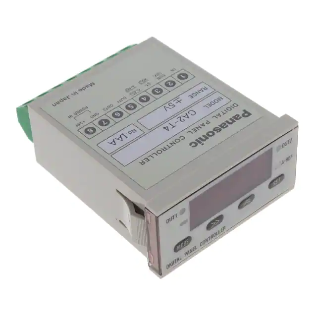
Ultra-compact Digital Panel Controller
NPS
ON / OFF Input
Conforming to
EMC Directive
Ultra-compact
Large display
Flexible scaling
Ultra-compact size of W 48�H 24�D 65.5 mm
W 1.890�H 0.945�D 2.579 in.
It can be mounted even in a tight space.
Though the size is compact, the measurement display uses 4 digit, 8 mm
0.315 in letter height, red 7-segment
LEDs.
The conversion of input values to a
different scale can be simply done by
key operation.
Since the need to convert the displayed
value is eliminated, the required
information can be confirmed immediately.
24 mm
0.945 in
Letter height
8mm
(0.315 in)
65.5 mm
2.579 in
20 mA
50 MPa
CA2 input
PS-18V-U
Power Supply
CA2
CA
Analog Input
Convenient functions
packed in a small
body!
48 mm
1.890 in
Conversion
4 mA
Displayed value
(pressure)
SENSOR CONTROLLERS
CA2 SERIES
0 Pa
Incorporates useful functions
Changing each threshold level is cumbersome
Measurement with master workpiece as standard
aAuto-reference function is useful!
aZero-adjust function is useful!
Auto-reference function is an original function developed by
SUNX by which, for example, if there is a reference
pressure change during pressure measurement, the
change is automatically added to the threshold level.
Hence, you need not change the threshold level every time.
Zero-adjust function enables setting of the standard
measured value to ‘0’. Hence, it is useful for an error check
by taking the measured master workpiece value as
standard.
OK
OK
OK
OK?
Threshold
level
NG Reference
pressure
increase
Before reference pressure
change
NG
Threshold
level shift
Analog
fiber
sensor
After reference pressure change
Product can be judged Without auto-reference
as OK or NG.
function
Due to change in reference
pressure, even an NG product
is judged as an OK product.
864
Application
� Judging
object height
With auto-reference
function
If auto-reference input is
fed before pressure level
judgement, when the reference pressure changes,
the threshold levels are
automatically
changed
accordingly and correct
judgment is possible.
Height judgment
is easily done by
using the zeroadjust function
and setting the
measured values
of the master
workpiece as ‘0’.
Ramco Innovations - 1207 Maple Street, West Des Moines IA USA 50265 - 800-280-6933 - www.ramcoinnovations.com
�APPLICATIONS
Detecting improper lathe chuck tightening
High accuracy eddy
current type
displacement sensor
Wide beam
fiber
Analog
fiber
sensor
Analog Input
CA
CA2
LED collimated
beam sensor
Measuring inner diameter of rings
ON / OFF Input
NPS
Thickness distinction
SENSOR CONTROLLERS
CA2
Measuring turbidity in water tank
The turbidity in the water tank can be
measured in an analog manner.
Power Supply
PS-18V-U
Laser collimated
beam sensor
Two independent outputs incorporated
Two independent comparative outputs (OUT 1, OUT 2) have been incorporated. High output comparison operation / low
output comparison operation can be set for each output.
Further, the hysteresis for each of the outputs can be set arbitrarily.
Comparative output
Hysteresis
ON
OFF
OUT 1
Hysteresis
OUT 2
OUT 1 threshold value
ON
OFF
OUT 2 threshold value
OUT 1: ‘L’, OUT 2: ‘L’
Hysteresis
ON
OFF
OUT 1
Hysteresis
OUT 2
OUT 1 threshold value
ON
OFF
OUT 2 threshold value
Various input ranges
Low price
The CA2 series is provided with 5 types
of input ranges: 4 to 20 mA, 1 to 5 V,
�1 V, �5 V and �10 V.
It can be used with any suitable analog
sensor.
It saves space by incorporating various
functions in an extremely small size.
Further, it is low priced.
4 to 20 mA
1 to 5 V
�1 V
�5 V
�10 V
Independent two low output comparison operation
Comparative output
OUT 1: ‘H’, OUT 2: ‘H’
Independent two high output comparison operation
Comparative output
OUT 1: ‘H’, OUT 2: ‘L’
Independent high and low output comparison operation
Hysteresis
ON
OFF
OUT 1
Hysteresis
OUT 2
OUT 1 threshold value
ON
OFF
OUT 2 threshold value
5 types of input ranges
are available.
Ramco Innovations - 1207 Maple Street, West Des Moines IA USA 50265 - 800-280-6933 - www.ramcoinnovations.com
865
�ORDER GUIDE
Appearance
Input range
Model No.
4 to 20 mA
CA2-T1
1 to 5 V
CA2-T2
�1 V
CA2-T3
�5 V
CA2-T4
�10 V
CA2-T5
Output
NPN open-collector
transistor
PS-18V-U
Power Supply
CA2
CA
Analog Input
NPS
ON / OFF Input
SENSOR CONTROLLERS
CA2
866
Ramco Innovations - 1207 Maple Street, West Des Moines IA USA 50265 - 800-280-6933 - www.ramcoinnovations.com
�SPECIFICATIONS
Model No.
CA2-T1
CA2-T2
CA2-T3
CA2-T4
CA2-T5
Item
Power consumption
4 to 20 mA
1 No.
Single end input
A/D conversion method
Selectable from 200 times/sec., 20 times/sec., 10 times/sec. or 5 times/sec.
Input condition: Non-voltage contact or NPN open-collector transistor input
Signal condition: Negative logic, Input time duration 10 ms or more
Signal level: ON ... 1.5 V or less (output current: 10 mA or less)
OFF ... Supply voltage or open
Guaranteed No. of zero-adjust input usage: 10 million times or less (for zero-adjust back-up setting)
High level (supply voltage, or open): Start, Low level (1.5 V or less): Hold
NPN open-collector transistor
• Maximum sink current: 100 mA
• Applied voltage: 35 V DC or less (between comparative output and GND)
• Residual voltage: 1.3 V or less (at 100 mA sink current)
0.4 V or less (at 16 mA sink current)
Comparative outputs
(OUT 1, OUT 2)
Utilization category
DC-12 or DC-13
Response time
5 ms or less (when start / hold input is used at a sampling rate of 200 times/sec.)
Hysteresis
Variable from 1 to 3,999
Display
4 digit 7-segment red LED display (letter height: 8 mm 0.315 in)
Selectable from 20 times/sec., 10 times/sec., 5 times/sec., 2.5 times/sec., 1 time/sec. or 0.5 time/sec.
Selectable span of 4,000 Nos. between �9999 to�9999 is displayed. (‘�’ is not displayed)
Display range
�(0.1 % F.S.�1 digit) at 23�5 °C 73.4�41 °F, 35 to 85 % RH
Display accuracy
�0.5 % F.S. over 0 to�50 °C �32 to�122 °F
Temperature characteristics
Setting resolution
1 digit
�9999 to�9999
Threshold value setting range
Polarity indication
OUT 1 operation
OUT 2 operation
Auto-reference operation
Functions
Pollution degree
Ambient temperature
Red LED (lights up when the displayed value or the threshold value is negative)
mode: Lights up when OUT 1 is ON. Blinks when display is changed to OUT 1 threshold value display.
( Measurement
Setting mode: Blinks when OUT 1 threshold value and comparison conditions are set or when zero scale of scale setting function is set. )
Measurement mode: Lights up when OUT 2 is ON. Blinks when display is changed to OUT 2 threshold value display.
Orange LED (
Setting mode: Blinks when OUT 2 threshold value and comparison conditions are set or when full scale of scale setting function is set. )
Orange LED
Green LED (lights up when auto-reference function is used)
Auto-reference function, zero-adjust function, scale setting function, threshold value setting function, hysteresis setting function,
comparative output timer function, start / hold function, memory clear function, power supply ON-delay function etc.
3 (Industrial environment)
0 to�55 °C �32 to�131 °F (No dew condensation), Storage: �20 to�70 °C �4 to�158 °F
Ambient humidity
35 to 85 % RH, Storage: 35 to 85 % RH
EMC
EN 50081-2, EN 50082-2, EN 61000-6-2
Voltage withstandability
�10 V
Successive approximation method
Start / hold input
Display refresh rate
�5 V
1 MΩ
Input method
Zero-adjust input
(0-ADJ.)
Auto-reference input
(A-REF.)
Indicators
�1 V
No. of inputs
Sampling rate
Environmental resistance
1 to 5 V
20 Ω
1,500 V AC for one min. between all supply terminals connected together and enclosure
Insulation resistance
100 MΩ, or more, with 500 V DC megger between all supply terminals connected together and enclosure
Vibration resistance
10 to 55 Hz frequency, 1.5 mm 0.059 in amplitude in X, Y and Z directions for two hours each
Shock resistance
Back-up memory
294 m/s2 (30 G) acceleration in X, Y and Z directions for three times each
Non-volatile memory (EEPROM), Guaranteed write operations: 1,000,000 or less
Material
Enclosure: Polycarbonate
Connecting method
Terminal block connection
Weight
Analog Input
CA
CA2
Input impedance
2.8 W or less
Power Supply
PS-18V-U
Analog inputs
Input range
ON / OFF Input
NPS
24 V DC�10 % Ripple P-P 10 % or less
Supply voltage
55 g approx.
Ramco Innovations - 1207 Maple Street, West Des Moines IA USA 50265 - 800-280-6933 - www.ramcoinnovations.com
SENSOR CONTROLLERS
CA2
867
�I/O CIRCUIT AND WIRING DIAGRAMS
Input circuit diagram
Terminal arrangement
IN, ST / HOLD, 0-ADJ. / A-REF.
(Note)
Terminal No.
NPS
ON / OFF Input
SENSOR CONTROLLERS
CA2
Main circuit
7.5 kΩ
�24 V
1
1
IN
IN
2.2 kΩ
3
7.5 kΩ
4
5
6
8
24 V DC
�10 %
Start / hold
input m1
m1
0-ADJ. /
A-REF.
5 COM.
(0 V)
Internal circuit
7
COM. ST / 0-ADJ. / OUT 1 OUT 2 GND �24 V
(0 V) HOLD A-REF.
– +
m1
4
CA2
CA
Analog Input
3
m1
ST / HOLD
2.2 kΩ
Signal
input Zero-adjust /
auto-reference
input
Users’ circuit
Load
Comparative output
OUT 2
Load
Comparative output
OUT 1
Note: COM. (0 V) is internally connected to GND.
Output circuit diagram
m1
OUT 1, OUT 2
Non-voltage contact or NPN open-collector transistor
Terminal No.
D
Main circuit
8
PS-18V-U
Power Supply
2
5
Tr1
ZD1
6
Tr2
ZD2
7
Internal circuit
�24 V
or
Load
OUT 1
Load
100 mA max.
OUT 2
�
�
24 V DC
�10 %
ON: 1.5 V or less (output current 10 mA or less)
OFF: Supply voltage, or open
100 mA max.
GND
Users’ circuit
Symbols ... D: Reverse supply polarity protection diode
ZD1, ZD2: Surge absorption zener diode
Tr1, Tr2 : NPN output transistor
PRECAUTIONS FOR PROPER USE
This product is not a safety controller. It does not
possess control functions needed for accident
prevention or safety maintenance.
Functional description
3
1
4
5
2
Description
Function
• Measurement mode: Lights up when OUT 2 is ON.
Blinks when display is changed
OUT 2 operation
to OUT 2 threshold value display.
4 indicator
• Setting mode: Blinks when OUT 2 threshold value
(Orange)
and comparison conditions are set
or when full scale of scale setting
function is set.
Auto-reference
5 operation indicator • Lights up when auto-reference function is used.
(Green)
6
9
7
Description
1 Display (Red)
2
Polarity
indicator (Red)
8
Function
• Measurement mode: Display of scaled measured value,
input value, OUT 1 threshold
value and OUT 2 threshold value
• Setting mode: Display of setting menu and setting
parameters
• Error: Display of error code
• When the set key is pressed while pressing the
mode key, the sensor changes from measurement
mode to setting mode. Further, it changes the
mode in the setting mode.
7 Shift key
• It shifts the settable digit.
8 Increment key
• It changes the setting or the numerical value to be
set. The setting is shown on the display. The
setting is selected by the increment key and
confirmed by the set key. When a numerical value
is to be set, the settable digit blinks. The blinking
digit is incremented by pressing the increment key.
• It can also be used to directly display the input
value.
9 Set key
• It changes the item to be set in the setting mode.
The item to be set and the conditions are confirmed
by the set key.
• It can also be used to change to threshold value
display in the measurement mode.
• Lights up when the displayed value or the threshold
value is negative.
• Measurement mode: Lights up when OUT 1 is ON.
Blinks when display is changed
OUT 1 operation
to OUT 1 threshold value display.
3 indicator
• Setting mode: Blinks when OUT 1 threshold value
(Orange)
and comparison conditions are set
or when zero scale of scale setting
function is set.
868
6 Mode key
Ramco Innovations - 1207 Maple Street, West Des Moines IA USA 50265 - 800-280-6933 - www.ramcoinnovations.com
�PRECAUTIONS FOR PROPER USE
Functions at a glance
Function
Scale setting
function
CA2 display Analog sensor
value
output voltage
• Using this function, the input value range can be converted to an arbitrary display range (span of 4,000 Nos.
within �9,999 to�9,999).
• The values which are desired to be displayed by the
extreme values of the input value range are input as
‘zero scale’ and ‘full scale’.
Example: In case ‘beam interrupted width’ is to be
displayed when using the analog sensor
LA-510 having an output of 1 to 5 V.
Zero-adjust
function
Since the LA-510 outputs an analog voltage of
1 to 5 V, CA2-T2, which has an input range of
1 to 5 V, is used.
If Zero scale: 1500
Full scale: 0000
Full beam Full beam
interruption reception
Time chart
Full beam received condition
Full beam interrupted condition
Full beam Full beam
interruption reception
(1 V)
(5 V)
Comparative
output timer
function
15 mm 0.591 in
Sensing
Sensing
condition
1500
0000
• By making the zero-adjust (0-ADJ.) input low for 10 ms,
or more, the output value is forcibly made ‘0’ and
measurement is then done by taking the input value of
this instant as standard ‘0’.
• Zero-adjust function cannot be used when autoreference function is selected.
• If zero-adjust backup is used, the input value is stored
even when the power supply is switched off.
• To cancel the zero-adjust function, put the zero-adjust
setting to OFF. In this case, the standard value will return
to the value before zero-adjust input.
• ON-delay: It makes short duration sensing signal ineffective.
• OFF-delay: It extends the output signal by a fixed time
period (0 to 99.99 sec.).
5V
1V
0V
Details
Not sensing
ON
Normal
operation
ON / OFF Input
NPS
Details
Analog Input
CA
CA2
Function
SENSOR CONTROLLERS
CA2
OFF
Comparative outputs
Comparative outputs
Comparative outputs
OUT 1 set value
Hysteresis
OUT 1
T
T
OFF
Timer period T: 0 to 99.99 sec. (settable in units of 0.01 sec.)
• This function maintains the output display and the
comparative outputs (OUT 1, OUT 2) based on the input
value at start / hold (ST / HOLD) input falling edge and
restores normal operation at the start / hold input rising
edge.
Input value
Display value
Start / Hold
function
Start / Hold
(ST / HOLD)
input
t
t
High(OFF)
Low(ON)
Input signal condition t: 10 ms or more (sampling rate 200 times/sec.)
100 ms or more (sampling rate 20 times/sec.)
200 ms or more (sampling rate 10 times/sec.)
400 ms or more (sampling rate 5 times/sec.)
OUT 2 set value
ON
OFF
Memory clear
function
• This function clears all settings and returns the controller
to the initial setting condition.
• This function is activated by pressing the set key while
pressing the shift key for 3 sec. or more.
• This function enables independent setting of the hysteresis
(difference between ON and OFF points) of the comparative
outputs (OUT 1, OUT 2) in the range 1 to 3,999.
Power supply
ON-delay function
• This function delays the commencement of measurement by the set time period (0 to 9,999 sec.) from the
instant the power supply is switched on.
• This function automatically compensates the threshold
values according to a change in the reference input value.
• When the auto-reference (A-REF.) input is made Low, the
measured value at that instant is added to each threshold value
(OUT 1, OUT 2 set values) to give the new threshold values.
Display refresh
rate selection
function
• This function selects the refresh rate of the measurement
value display from 20 times/sec., 10 times/sec.,
5 times/sec., 2.5 times/sec., 1 time/sec. and, 0.5 time/sec.
• It does not affect the comparison operation.
Hysteresis
OUT 2
OUT 1 set value
OUT 2 set value
OUT 1’
OUT 2’
OUT 1
OUT 2
Auto-reference
(A-REF.)
input
t
ON
OFF
New threshold values
Auto-reference
function
OUT 1: ‘L’
OUT 2: ‘L’
Independent two
low output
comparison
operation
ON
T
OFF-delay
ON
OFF
Hysteresis
ON
OFF
OUT 2
T
OFF
Hysteresis
OUT 1
Change in
reference
value
Hysteresis
setting function
OUT 1: ‘H’
OUT 2: ‘H’
Independent two
high output
comparison
operation
Initial threshold values
Threshold
value setting
function
ON-delay
High (OFF)
Low (ON)
t: 10 ms or more
• It can be selected whether auto-reference function is to
be used or not.
• Auto-reference operation indicator (green) lights up
when auto-reference function is used.
• Auto-reference function cannot be used when zeroadjust function is selected.
• This function selects the sampling rate for measurement from
Sampling rate
selection function 200 times/sec., 20 times/sec., 10 times/sec. and, 5 times/sec.
Decimal point position
• This function sets the position of the decimal point.
setting function
Zero-suppression • This function removes an unnecessary ‘0’ in the upper digits.
setting function
(e.g.): 0460 n 460
• This function fixes the least significant digit display to ‘0’.
LSD (least significant digit)
• It merely fixes the least significant digit display and does
fixed ‘0’ display function
not affect the comparison operation.
Key-protect
function
• This function makes the increment key ineffective so that the
set conditions are not changed by mistake. [When the keyprotect function is canceled, the increment key is usable.]
Ramco Innovations - 1207 Maple Street, West Des Moines IA USA 50265 - 800-280-6933 - www.ramcoinnovations.com
869
Power Supply
PS-18V-U
ON
• Using this function, the threshold value for OUT 1 and
OUT 2 can be set from �9,999 to�9,999.
• ‘H’ and ‘L’ are displayed in the threshold value setting
mode. If ‘H’ is set, high output comparison operation is
obtained, and if ‘L’ is set, low output comparison
operation is obtained.
Each comparative output and each threshold value is
independent.
OUT 1: ‘H’
Hysteresis
ON
OUT 2: ‘L’
OUT 1
OFF
Independent high
Hysteresis ON
and low output
OUT 2
OFF
comparison
operation
OUT 1 set value OUT 2 set value
�SENSOR CONTROLLERS
NPS
ON / OFF Input
CA2
CA
Analog Input
PS-18V-U
Power Supply
CA2
PRECAUTIONS FOR PROPER USE
Ferrite clamp
• If this product is to be used as a CE (European standard
EMC Directive) approved product, make sure to connect
ferrite clamps, with one loop, on all the connection cables,
as shown in the right figure.
Also, make sure not to exceed 10 m 32.808 ft in cable
length.
Ferrite clamp
Manufactured by TDK Corporation:
Noise filter for single line
ZCAT3035-1330
DIMENSIONS (Unit: mm in)
CA2-�
The CAD data in the dimensions can be downloaded from the SUNX website: http://www.sunx.co.jp/
Digital panel controller
Panel cut-out dimensions
44
1.732
(40)
(1.575)
Terminal
block
21
0.827
(10)
(0.394)
�0.6
45
0
�0.024
1.772
0
�0.4
22
0
�0.016
0.866
0
(10)
(0.394)
Note: The panel thickness should be 0.5 to 4 mm 0.020 to 0.157 in.
55.5
2.185
4.5
0.177
OUT 1 operation indicator
(Orange)
24
0.945
Polarity indicator
(Red)
Mode key
Shift key
870
22
0.866
45
1.772
OUT 2 operation indicator
(Orange)
Display (Red)
MODE
SET
48
1.890
Auto-reference operation indicator
(Green)
Set key
Increment key
Ramco Innovations - 1207 Maple Street, West Des Moines IA USA 50265 - 800-280-6933 - www.ramcoinnovations.com
�