CQ
1 FORM C AUTOMOTIVE
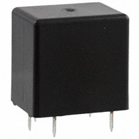
SILENT RELAY
CQ RELAYS (ACQ)
FEATURES
TYPICAL APPLICATIONS
• Sound pressure reduced by approx.
20 dB from that of the company’s
non-silent relays
• Space saving
• Adopting standard terminal pitch (for
compact relays)
• Plastic sealed type
• Wiper load models are listed
For intermittent wipers and
applications requiring quiet operation
ORDERING INFORMATION
CQ
-
Contact arrangement
1: 1 Form C
W1: 1 Form C for wiper load
Coil voltage (DC)
12 V
TYPES
Contact arrangement
1 Form C
1 Form C for wiper load
Coil voltage
Model No.
ACQ131
ACQW131
12V DC
Part No.
CQ1-12V
CQ1W-12V
Standard packing; Carton (tube): 40 pcs.; Case: 800 pcs.
RATING
1. Coil data
Nominal coil
voltage
Pick-up voltage
(at 20C 68F)
Drop-out voltage
(at 20C 68F)
Nominal operating
current
[10%] (at 20C 68F)
Coil resistance
[10%] (at 20C 68F)
Nominal operating
power
Usable voltage range
12V DC
Max. 7.2V DC
(Initial)
Min. 1.0V DC
(Initial)
53.3 mA
225
640 mW
10 to 16V DC
Note: Other pick-up voltage types are also available. Please contact us for details.
ds_61208_en_cq: 310113D
1
�CQ
2. Specifications
1) Standard CQ relay
Characteristics
Contact
Rating
Electrical
characteristics
Mechanical
characteristics
Item
Arrangement
Contact resistance (Initial)
Contact voltage drop
Contact material
Nominal switching capacity (resistive load)
Nominal operating power
Min. switching capacity (resistive load)*1
Specifications
1 Form C
N.O.: Typ7m, N.C.: Typ8m (By voltage drop 6V DC 1A)
Max. 0.2V (at 10 A)
Ag alloy (Cadmium free)
N.O.: 20A 14V DC, N.C.: 10A 14V DC
N.O.: 35A for 2 minutes, 25A for 1 hour (at 20C 68F)
30A for 2 minutes, 20A for 1 hour (at 85C 185F)
640 mW
1A 14V DC
Insulation resistance (Initial)
Min. 100 M (at 500V DC, Measurement at same location as “Breakdown voltage” section.)
Between open contacts
Between contacts and coil
Operate time (at nominal voltage)
Release time (at nominal voltage)
Functional
Shock resistance
Destructive
Functional
Vibration resistance
Destructive
500 Vrms for 1 min. (Detection current: 10mA)
500 Vrms for 1 min. (Detection current: 10mA)
Max. 10ms (at 20C 68F, excluding contact bounce time) (Initial)
Max. 10ms (at 20C 68F, excluding contact bounce time) (Initial)
Min. 100 m/s2 {10G} (Half-wave pulse of sine wave: 11ms; detection time: 10s)
Min. 1,000 m/s2 {100G} (Half-wave pulse of sine wave: 6ms)
10 Hz to 100 Hz, Min. 44.1 m/s2 {4.5G} (Detection time: 10s)
10 Hz to 500 Hz, Min. 44.1 m/s2 {4.5G}
Time of vibration for each direction; X, Y direction: 2 hours, Z direction: 4 hours
Min. 107 (at 120 cpm)
Min. 105 (at nominal switching capacity, operating frequency: 1s ON, 9s OFF)
Min. 3105 (Inrush 30A, steady 5A, 20A 14V DC at brake current)
(Operating frequency: 1s ON, 2s OFF)
Ambient temperature: –40C to +85C –40F to +185F
Humidity: 5% R.H. to 85% R.H. (Not freezing and condensing at low temperature)
6 cpm (at nominal switching capacity)
Approx. 6.5g .23 oz
Max. carrying current (12V DC initial)*3
Breakdown voltage
(Initial)
Mechanical
Expected life
Conditions
Electrical*4
Conditions for operation, transport and storage*2
Max. operating speed
Mass
Notes:
*1.This value can change due to the switching frequency, environmental conditions, and desired reliability level, therefore it is recommended to check this with the actual load.
*2.The upper operation ambient temperature limit is the maximum temperature that can satisfy the coil temperature rise value. Refer to “6. Usage, Storage and Transport
Conditions“ in AMBIENT ENVIRONMENT section in Relay Technical Information.
*3.Depends on connection conditions. Also, this does not guarantee repeated switching. We recommend that you confirm operation under actual conditions.
*4.Motor load does not apply to wiper load applications.
2) For wiper load (ACQW131)
Anything outside of that given below complies with standard CQ relays.
Characteristics
Rating
Item
Max. carrying current (12V DC initial)*1
Expected life
Electrical
Specifications
N.O.: 25A for 1 minutes, 15A for 1 hour (at 20C 68F)
N.O. side: Min. 5105 (Inrush 25A, steady 6A 14V DC)
N.C. side: Min. 5105 (12A 14V DC at brake current)
(Operating frequency: 1s ON, 9s OFF)
Note: *1. Depends on connection conditions. Also, this does not guarantee repeated switching. We recommend that you confirm operation under actual conditions.
2
ds_61208_en_cq: 310113D
�CQ
REFERENCE DATA
40
(N.O. side Room temperature)
35
Coil applied voltage, VDC
60
Switching voltage, VDC
2. Ambient temperature and operating voltage
range
50
40
30
20
30
25
20
10
10
0
Operating voltage range
15
5
0
10
20
30
40
Switching current, A
0
−40 −20
50
3. Ambient temperature characteristics
80
Ratio against the rated voltage, %
1. Max. switching capability (Resistive load,
initial)
70
Pick-up voltage
upper limit
60
50
40
30
20
Pick-up voltage lower limit
10
Pick-up voltage
(Cold start)
0
20 40 60 8085 100 120
Ambient temperature, °C
0
−40
85
20
Ambient temperature, °C
4. Distribution of pick-up and drop-out voltage
5. Distribution of operate time
6. Distribution of release time
Sample: ACQ131, 100pcs
Sample: ACQ131, 100pcs
Sample: ACQ131, 100pcs
Quantity, n
Quantity, n
50
40
30
20
10
100
100
90
90
80
80
70
70
Quantity, n
Pick-up voltage
Drop-out voltage
60
50
40
30
20
20
10
10
9
7
6
Pick-up voltage
Max.
x
Min.
5
4
Drop-out voltage
2
Max.
x
Min.
0
10
25
No. of operations, × 104
8.-(2) Operation noise distribution
When operate
When release
25
25
20
20
Quantity, n
Quantity, n
8.-(1) Operation noise distribution
10
5
5
50
52
ds_61208_en_cq: 310113D
54
56
3
3.5
N.C. side
N.O. side
40
30
Max.
x
Max.
Min.
x
Min.
20
50
10
0
0
10
25
No. of operations, × 104
0
50
Measuring conditions
Sample: ACQ131, 50 pcs.
Equipment setting: “A” weighted, Fast, Max. hold
Coil voltage: 12V DC
Coil connection device: Diode
Background noise: Approx. 20dB
15
10
Noise level, dB
2.5
3
0
48
2
50
8
1
15
1.5
Change of contact resistance
10
M
46
1
Time, ms
Change of pick-up and drop-out voltage
Pick-up and drop-out voltage, V
Sample: ACQW131
Quantity: n = 3
Load: N.O. side: Inrush 25A, steady 6A 14V DC
N.C. side: Brake current 12A 14V DC
Operating frequency: ON 1s, OFF 9s
Ambient temperature: Room temperature
Circuit
44
0.5
Time, ms
7. Electrical life test for wiper load (motor free)
42
0
0
1.5 2.0 2.5 3.0 3.5 4.0 4.5 5.0 5.5 6.0 6.5
Voltage, V
0
50
30
0
1.5 2.0 2.5 3.0 3.5 4.0 4.5 5.0 5.5 6.0 6.5 7.0 7.5 8.0
* Without diode
60
40
Contact resistance, mΩ
60
Microphone
Relay
50mm
1.969inch
Sponge
38
40
42
44
46
48
50
52
Noise level, dB
3
�CQ
DIMENSIONS (mm inch)
CAD Data
Data from our Web site.
Download CAD
External dimensions
CAD Data
17.0
.669
PC board pattern (Bottom view)
5×1.5+0.1
0 dia.
5×.059+.004
dia.
0
13.0
.512
10.0
.394
16.6
.654
Max.
1.0
.039
0.4
.016
CAD Data
3.5
.138
5×0.25
5×.010
10.2
.402
2.5
.098
Tolerance: 0.1 .004
*A
5×1.2
Pre-soldering 5×.047
Schematic (Bottom view)
NO
10.0
.394
1.5
.059
2.5
.098
10.2
.394
COM
Dimension:
Max. 1mm .039 inch:
1 to 3mm .039 to .118 inch:
Min. 3mm .118 inch:
Tolerance
0.1 .004
0.2 .008
0.3 .012
COIL
NC
* Dimensions (thickness and width) of terminal is measured before pre-soldering.
Intervals between terminals is measured at A surface level.
For Cautions for Use, see Relay Technical Information.
4
ds_61208_en_cq: 310113D
�


 工商网监
湘ICP备2023018690号
工商网监
湘ICP备2023018690号
