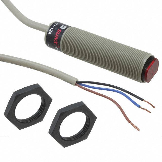
CY
SERIES
Cylindrical Photoelectric Sensor
Amplifier Built-in
Cylindrical type easily
mountable with M18
thread
(
M18 thread
Easy to replace
This sensor has an M18 thread size for
convenient mounting.
A pigtailed type sensor with connector
(CY-�-J), which is easy to replace, is
also available.
Conforming to
EMC Directive
AC supply type conforms to
Low Voltage Directive, too.
)
UL Recognition
Long sensing range
Thru-beam type
12 m 39.370 ft
Retroreflective type
3 m 9.843 ft
���� ���
����
�����
�� ��� � ����� ���
Diffuse reflective type
M18
120 mm
4.724 in
Wide product range
Environment resistant
Convenient options
Supply voltage
1 AC supply type (24 to 240 V AC)
2 DC supply type (10 to 30 V DC)
Its IP67 construction can be hosed down
with water. In addition, it has strong
resistance against vibration since it is
filled up with resin.
The connector also has IP67 protection.
The beam is bent at a right angle with
the side-view attachment.
Output
1 NPN open-collector transistor
2 PNP open-collector transistor
3 AC non-contact (thyristor) output
Slit mask (For thru-beam type sensors only)
It is convenient for detecting
small objects or enhancing
the sensing accuracy.
Connection
1 Cable type
2 Pigtailed type
A total of 32 models are available.
Note: However, take care that if it is exposed to
water splashes during operation, it may
detect a water drop itself.
250
Side-view attachment (For thru-beam type sensors only)
08/2005
�CY
APPLICATIONS
Sensing cardboard boxes
Sensing specular objects
Sensing milk packs
ORDER GUIDE
Appearance
Sensing range
With polarizing
filters
Retroreflective
12 m
39.370 ft
1.5 m
4.921 ft (Note)
120 mm
4.724 in
Thru-beam
Retroreflective
Output
CY-21
NPN open-collector
transistor
CY-21-PN
PNP open-collector
transistor
CY-27
NPN open-collector
transistor
CY-27-PN
PNP open-collector
transistor
12 m
39.370 ft
CY-29
NPN open-collector
transistor
CY-29-PN
PNP open-collector
transistor
CY-22
NPN open-collector
transistor
CY-22-PN
PNP open-collector
transistor
120 mm
4.724 in
Selectable
either LightON or DarkON by the
control input
Light-ON
CY-11B
Dark-ON
CY-17A
Light-ON
Dark-ON
24 to 240 V AC
�10 %
1.5 m
4.921 ft (Note)
Output operation
CY-11A
CY-17B
With polarizing
filters
Supply voltage
10 to 30 V DC
3m
9.843 ft (Note)
Diffuse
reflective
AC supply type
Model No.
3m
9.843 ft (Note)
Diffuse
reflective
DC supply type
Thru-beam
Type
AC non-contact
(thyristor) output
CY-19A
Light-ON
CY-19B
Dark-ON
CY-12A
Light-ON
CY-12B
Dark-ON
NOTE: Reflector is not supplied with the retroreflective type sensor. Please select the suitable reflector or
reflective tape from the options.
Note: The sensing range of the retroreflective type sensor is specified for the RF-230 reflector (optional).
08/2005
251
�CY
ORDER GUIDE
Pigtailed type
Pigtailed type is also available.
• Table of Model Nos.
NPN output
PNP output
Light-ON
Dark-ON
AC supply type
DC supply type
Type
Standard
Thru-beam
CY-21
CY-21-J
Retroreflective
CY-27
CY-27-J
CY-29
CY-29-J
Diffuse reflective
CY-22
CY-22-J
Thru-beam
CY-21-PN
CY-21-PN-J
Retroreflective
CY-27-PN
CY-27-PN-J
With polarizing
filters
With polarizing
filters
" 14
Pigtailed type
(Note)
CY-29-PN
CY-29-PN-J
Diffuse reflective
CY-22-PN
CY-22-PN-J
Thru-beam
CY-11A
CY-11A-J
Retroreflective
CY-17A
CY-17A-J
With polarizing
filters
Diffuse reflective
CY-19A
CY-19A-J
CY-12A
CY-12A-J
Thru-beam
CY-11B
CY-11B-J
Retroreflective
CY-17B
CY-17B-J
With polarizing
filters
Diffuse reflective
CY-19B
CY-19B-J
CY-12B
CY-12B-J
200 mm
7.874 in
mm "0.551 in
Mating cable
Note: Please order the suitable mating cable separately.
• Mating cable
Type
For DC supply
type
(Note 1)
For AC supply
type
(Note 1)
Model No.
Description
CN-22-C2
Length: 2 m 6.562 ft
CN-22-C5
Length: 5 m 16.404 ft
CN-24-C2
Length: 2 m 6.562 ft
CN-24-C5
Length: 5 m 16.404 ft
CN-32-C2
Length: 2 m 6.562 ft
CN-32-C5
Length: 5 m 16.404 ft
CN-33-C2
Length: 2 m 6.562 ft
CN-33-C5
Length: 5 m 16.404 ft
• For the emitter of the thru-beam type sensor
(2-core) (Note 2)
• For the receiver of the thru-beam type sensor,
retroreflective type and diffuse reflective type
sensors (4-core) (Note 2)
• For the emitter of the thru-beam type sensor
(2-core)
• For the receiver of the thru-beam type sensor,
retroreflective type and diffuse reflective type
sensors (3-core)
Notes: 1) The DC supply type mating cable and the AC supply type mating cable have different connector
structure and so are not interchangeable.
Notes: 2) To use the test input (emission halt input) use the 4-core CN-24-C�.
252
08/2005
�CY
OPTIONS
Designation
Model No.
Description
Slit on emitter
Slit size
Slit on
11.6�0.5 mm
receiver
0.457�0.020 in
Slit mask
For thru-beam
type sensor only
(
OS-CYS
)
• Sensing range: 2.5 m 8.202 ft
• Min. sensing object: "8 mm "0.315 in
Slit on both
sides
• Sensing range: 0.8 m 2.625 ft
• Min. sensing object: 10�0.7 mm 0.394�0.028 in
Slit on emitter
• Sensing range: 5 m 16.404 ft
• Min. sensing object: "8 mm "0.315 in
Slit size
Slit on
11.6�1.5 mm
0.457�0.059 in receiver
• Sensing range: 4.5 m 14.764 ft
• Min. sensing object: "8 mm "0.315 in
Slit on both
sides
• Sensing range: 2 m 6.562 ft
• Min. sensing object: 10�2 mm 0.394�0.079 in
Slit on emitter
• Sensing range: 7.5 m 24.606 ft
• Min. sensing object: "8 mm "0.315 in
Slit size
Slit on
11.6�3 mm
receiver
0.457�0.118 in
• Sensing range: 7 m 22.966 ft
• Min. sensing object: "8 mm "0.315 in
Slit on both
sides
Side-view attachment
thru-beam
(For
type sensor only)
Reflector
For retroreflective
type sensor only
(
)
Reflector
mounting bracket
Reflective tape
For retroreflective
type sensor only
(
Sensor checker
(Note)
)
• Sensing range: 3 m 9.843 ft
• Min. sensing object: "8 mm "0.315 in
• Sensing range: 4.5 m 14.764 ft
• Min. sensing object: 10�3 mm 0.394�0.118 in
The beam is bent at a right angle by the attachments.
• Sensing range (with attachment on both sides): 8 m 26.247 ft
CY-SV1
RF-230
• Sensing range: 3 m 9.843 ft [CY-27� & CY-17�], 1.5 m 4.921 ft [CY-29� & CY-19�]
RF-220
• Sensing range: 2 m 6.562 ft [CY-27� & CY-17�], 1.2 m 3.937 ft [CY-29� & CY-19�]
RF-210
• Sensing range: 1 m 3.281 ft [CY-27� & CY-17�], 0.7 m 2.297 ft [CY-29� & CY-19�]
MS-RF21-1
Protective mounting bracket for RF-210
It protects the reflector from damage and maintains alignment.
MS-RF22
For RF-220
MS-RF23
For RF-230
RF-12
• Sensing range: 0.7 m 2.297 ft [CY-27� & CY-17�], 0.4 m 1.312 ft [CY-29� & CY-19�]
RF-11
• Sensing range: 0.5 m 1.640 ft [CY-27� & CY-17�]
CHX-SC2
It is useful for beam alignment of thru-beam type sensors.
The optimum receiver position is given by indicators, as well as an audio signal.
Note: Refer to p.414l for details on the sensor checker CHX-SC2.
Slit mask
Side-view attachment
Reflective tape
• OS-CYS
• CY-SV1
• RF-12
30 mm
1.181 in
• RF-11
0.7 mm
0.028 in
30 mm
1.181 in
8 mm
0.315 in
25 mm
0.984 in
0.7 mm
0.028 in
Reflector mounting bracket
Reflector
• RF-230
50.3 mm
1.980 in
• MS-RF23
• RF-220
8.3 mm
0.327 in
59.3 mm
2.335 in
35.3 mm
1.390 in
8.3 mm
0.327 in
Two M3 (length 8 mm
0.315 in) screws with
washers are attached.
42.3 mm
1.665 in
• MS-RF21-1
Two M4 (length 10 mm
0.394 in) screws with
washers are attached.
• RF-210
33.3 mm
1.311 in
12.8 mm
0.504 in
• MS-RF22
Two M3 (length 12 mm
0.472 in) screws with
washers are attached.
Sensor checker
11 mm
0.433 in
• CHX-SC2
�
���
CH
�
��
X-
SC
2
����� ���� ��
08/2005
253
�CY
SPECIFICATIONS
DC supply type
Model No.
Type
Retroreflective
Thru-beam
With polarizing filters
Diffuse reflective
NPN output type
CY-21
CY-27
CY-29
CY-22
PNP output type
CY-21-PN
CY-27-PN
CY-29-PN
CY-22-PN
Sensing range
12 m 39.370 ft
3 m 9.843 ft (Note 1)
1.5 m 4.921 ft (Note 1)
120 mm 4.724 in (Note 2)
Sensing object
"8 mm "0.315 in or more
opaque object
Item
"50 mm "1.969 in or more opaque "50 mm "1.969 in or more opaque,
or translucent object (Note 1)
translucent or specular object (Note 1)
15 % or less of operation
distance
Hysteresis
Repeatability
(perpendicular to sensing axis)
0.1 mm 0.004 in or less
Supply voltage
Current consumption
Output
Emitter: 20 mA or less
Receiver: 25 mA or less
25 mA or less
NPN open-collector transistor
• Maximum sink current: 100 mA
• Applied voltage: 30 V DC or less (between output and 0 V)
• Residual voltage: 1.5 V or less (at 100 mA sink current)
PNP open-collector transistor
• Maximum source current: 100 mA
• Applied voltage: 30 V DC or less (between output and�V)
• Residual voltage: 1.5 V or less (at 100 mA source current)
DC-12 or DC-13
Output operation
Selectable either Light-ON or Dark-ON by the control input
Short-circuit protection
Incorporated
Response time
2 ms or less
Incorporated
Operation indicator
Emission indicator
Red LED (lights up when the output is ON)
Red LED (lights up during
beam emission)
Pollution degree
3 (Industrial environment)
Environmental resistance
Protection
Ambient temperature
IP67 (IEC)
�25 to�55 �C �13 to�131 �F (No dew condensation or icing allowed), Storage:�30 to�70�C �22 to�158 �F
Ambient humidity
Ambient illuminance
35 to 85 % RH, Storage: 35 to 85 % RH
Sunlight: 10,000 ?x at the light-receiving face, Incandescent light: 3,000 ?x at the light-receiving face
EMC
Voltage withstandability
0.3 mm 0.012 in or less
10 to 30 V DC Ripple P-P 10 % or less
Utilization category
Test input (emission halt) function
Opaque, translucent
or transparent object
EN 50081-2, EN 50082-2, EN 60947-5-2
1,000 V AC for one min. between all supply terminals connected together and enclosure
Insulation resistance
20 MΩ, or more, with 250 V DC megger between all supply terminals connected together and enclosure
Vibration resistance
10 to 500 Hz frequency, 1.5 mm 0.059 in amplitude (10 G max.) in X, Y and Z directions for two hours each
500 m/s2 acceleration (50 G approx.) in X, Y and Z directions for three times each
Shock resistance
Emitting element
Material
Infrared LED (modulated)
Enclosure: PBT, Lens: Polycarbonate
Weight
Accessories
Infrared LED (modulated)
Enclosure: PBT, Front cover: Acrylic
0.34 mm2 4-core (thru-beam type emitter: 3-core) cabtyre cable, 2 m 6.562 ft long
Cable
Cable extension
Red LED (modulated)
Extension up to total 100 m 328.084 ft is possible with 0.34 mm2, or more, cable (thru-beam type: both emitter and receiver).
Emitter: 90 g approx.
Receiver: 100 g approx.
100 g approx.
Nut: 4 pcs.
Nut: 2 pcs.
NOTE: Reflector is not supplied with the retroreflective type sensor. Please select the suitable reflector or
reflective tape from the options.
Notes: 1) The sensing range and the sensing object of the retroreflective type sensor are specified for the RF-230 reflector (optional).
Notes: 2) The sensing range of the diffuse reflective type sensor is specified for white non-glossy paper (200�200 mm 7.874�7.874 in) as the object.
254
08/2005
�CY
SPECIFICATIONS
AC supply type
Item
Model No.
Type
Retroreflective
Thru-beam
With polarizing filters
Light-ON
CY-11A
CY-17A
CY-19A
CY-12A
Dark-ON
CY-11B
CY-17B
CY-19B
CY-12B
Sensing range
Sensing object
12 m 39.370 ft
3 m 9.843 ft (Note 1)
"8 mm "0.315 in or more
opaque object
1.5 m 4.921 ft (Note 1)
"50 mm "1.969 in or more opaque "50 mm "1.969 in or more opaque,
or translucent object (Note 1)
translucent or specular object (Note 1)
Repeatability
(perpendicular to sensing axis)
0.1 mm 0.004 in or less
2.7 VA or less
AC non-contact (thyristor) output
• Load current: 5 to 200 mA
• Applied voltage: 24 to 240 V AC�10 %
• Residual voltage: 4 V AC or less (at 200 mA load current)
Response time
Power indicator
20 ms or less
Red LED (lights up when the output is ON), incorporated on the receiver for the thru-beam type sensor
Red LED (lights up when the power
is ON), incorporated on the emitter
Pollution degree
3 (Industrial environment)
IP67 (IEC)
Protection
Ambient temperature
�25 to�55 �C �13 to�131 �F (No dew condensation or icing allowed),
Ambient humidity
Ambient illuminance
Storage:�30 to�70 �C �22 to�158 �F
35 to 85 % RH, Storage: 35 to 85 % RH
Sunlight: 10,000 ?x at the light-receiving face, Incandescent light: 3,000 ?x at the light-receiving face
EMC
Voltage withstandability
0.3 mm 0.012 in or less
Emitter: 1.5 VA or less
Receiver: 2.5 VA or less
Output
Operation indicator
Opaque, translucent
or transparent object
24 to 240 V AC�10 %
Supply voltage
Power consumption
120 mm 4.724 in (Note 2)
15 % or less of operation
distance
Hysteresis
Environmental resistance
Diffuse reflective
EN 50081-2, EN 50082-2, EN 60947-5-2
1,500 V AC for one min. between all supply terminals connected together and enclosure
Insulation resistance
20 MΩ, or more, with 500 V DC megger between all supply terminals connected together and enclosure
Vibration resistance
10 to 500 Hz frequency, 1.5 mm 0.059 in amplitude (10 G max.) in X, Y and Z directions for two hours each
Shock resistance
Emitting element
Material
500 m/s2 acceleration (50 G approx.) in X, Y and Z directions for three times each
Infrared LED (modulated)
Enclosure: PBT, Lens: Polycarbonate
Cable
Cable extension
Weight
Accessories
Red LED (modulated)
Infrared LED (modulated)
Enclosure: PBT, Front cover: Acrylic
0.34 mm2 3-core (thru-beam type emitter: 2-core) cabtyre cable, 2 m 6.562 ft long
Extension up to total 100 m 328.084 ft is possible with 0.34 mm2, or more, cable (thru-beam type: both emitter and receiver).
Emitter: 90 g approx.
Receiver: 100 g approx.
100 g approx.
Nut: 4 pcs.
Nut: 2 pcs.
NOTE: Reflector is not supplied with the retroreflective type sensor. Please select the suitable reflector or
reflective tape from the options.
Notes: 1) The sensing range and the sensing object of the retroreflective type sensor are specified for the RF-230 reflector (optional).
Notes: 2) The sensing range of the diffuse reflective type sensor is specified for white non-glossy paper (200�200 mm 7.874�7.874 in) as the object.
08/2005
255
�CY
I/O CIRCUIT AND WIRING DIAGRAMS
NPN output type
I/O circuit diagram
Wiring diagram
����
Color code / Connector pin No. of the pigtailed type
(Brown / 1)�V
Sensor circuit
D
ZD
(Black / 4) Output (Note 1)
100 mA max. m1
(Violet / 2) Test input
(emission halt input) (Note 2)
(Pink / 2) Control input (Note 1)
Tr
Internal circuit
����
����
Load
�
10 to 30 V DC
�
����
m�
�
�
�� �� �� ��
�
��
(Blue / 3) 0 V
UsersÕ circuit
���
Notes: 1) The emitter of the thru-beam type sensor does
not incorporate the output and the control input.
Notes: 1) When the mating cable is connected to the
pigtailed type, the color of the control input wire is
white.
Notes: 2) Test input (emission halt input) is incorporated
only on the emitter of the thru-beam type sensor.
Notes: 2) When the mating cable is connected to the
pigtailed type, its color is white.
Connector pin position (Pigtailed type)
�
�
�
���
�� ��
��
�
���� ��� ���
��
�
� �� ���
��� ��
�
�� � �
�� ��
�
�� ��
������
��
m1
Symbols ... D : Reverse supply polarity protection diode
ZD : Surge absorption zener diode
Tr : NPN output transistor
Non-voltage contact or
NPN open-collector transistor
or
• Test input (emission halt input)
Low (0 to 2.5 V): Emission halt
High (6 to 30 V or open): Emission
• Control input
Low (0 to 1.5 V): Dark-ON
High (6 to 30 V, or open): Light-ON
Note: If opening the input cable, make sure to insulate it.
PNP output type
I/O circuit diagram
Wiring diagram
�
�
� �
�� � �
�����
� ��� �
�
� � � ��!� ���� �"��
����
� �������
�
��
������ � �������
����
#$�
%� � �&�'
��� �� �
�
#$� �* � ,& -����� #�
�� �&
m�
#'�
��� � +& ���� �����
#������
� �� �����& #�
�� +&
#)��* � +& �
���
� ����� #�
�� �&
����
�
�� �
(� ' �
�
����
�
�
�
��
#$��� � (& � '
������ �������
Notes: 1) The emitter of the thru-beam type sensor does
not incorporate the output and the control input.
Notes: 1) When the mating cable is connected to the
pigtailed type, the color of the control input wire is
white.
Notes: 2) Test input (emission halt input) is incorporated
only on the emitter of the thru-beam type sensor.
Notes: 2) When the mating cable is connected to the
pigtailed type, its color is white.
m�
�
����
�
�� �� �� ��
���
Connector pin position (Pigtailed type)
�
�
�
���
�� ��
��
�
���� ��� ���
��
�
� �� ���
��� ��
�
�� � �
�� ��
�
�� ��
������
��
m1
Symbols ... D : Reverse supply polarity protection diode
ZD : Surge absorption zener diode
Tr : PNP output transistor
Non-voltage contact or
PNP open-collector transistor
or
• Test input (emission halt input)
Low (0 to 1.5 V, or open): Emission
High (3 to 30 V): Emission halt
• Control input
Low [(supply voltage�6 V) or less, or open]: Light-ON
High [(supply voltage�1.5 V) or more]: Dark-ON
Note: If opening the input cable, make sure to insulate it.
256
08/2005
�CY
I/O CIRCUIT AND WIRING DIAGRAMS
AC non-contact
output type
I/O circuit diagrams
Wiring diagrams
Emitter of thru-beam type sensor
Emitter of thru-beam type sensor
����
Color code / Connector pin No. of the pigtailed type
Sensor circuit
(Brown / 1) AC IN
� �� � �
��
��� �
24 to 240 V AC
���
�10 %
(Blue / 3) AC IN
Internal circuit
Receiver of thru-beam type sensor, retroreflective & diffuse reflective type sensors
���
UsersÕ circuit
���
���
����
� ��
�� � ��
��� �
Connector pin position (Pigtailed type)
Receiver of thru-beam type sensor, retroreflective & diffuse reflective type sensors
Emitter of thru-beam type sensor
�����
��� � �����
�� ��� ��� ��
�� ���
�����
��
�
������ � �� �� ��
������
��
��
�
����
" � #� $�
��
�
%#
� %#& ' ��
���
����� � !� �� ��
��& (
Receiver of thru-beam type sensor, retroreflective & diffuse reflective type sensors
�
��
�����
��
��
� �� �
��
� �
�����
�� �� �
��
� �
�����
������
��
��
�
�
� �� �
��
� �
�����
�� �� �
�� ������
SENSING CHARACTERISTICS (TYPICAL)
All models
Correlation between setting distance and excess gain
�
�
CY-21�
CY-11�
������ ��
�
�
�
�
�
�
��
�
��
���� � ���
������ �����
�� ��
��
��� ���
���� � �� �
�
CY-21�
CY-11�
�
CY-27�
CY-17�
CY-29�
CY-19�
�
�
�
������ ����
�
������ ����
�
�
CY-22�
CY-12�
�
�
�
�
�
�
�
�
����� �� � ����� ������ � �� �
���
�� �
������ � �� ���
�
�
��
�
��
�����
��
� ��� � ���� ���
��
��� ���
���� � ��� ���
CY-27�
CY-17�
Thru-beam type
Parallel deviation
Angular deviation
Retroreflective type
Parallel deviation
Angular deviation
������ !�"���
�
�� ���
��
�����
��
�����
�
��� �
�
��
���� �
#
�������
����
�
���
�� � �� ���
"
�� �
�
��!"�
����
�� !
���������
�RF-230�
# �
��
���
�
��
�����
���
�
���
��
����
����
���� �
���
������
�����
��������� ����� ?��� ���
08/2005
��
��
�
��
����
���� �����
����
��
���
� ���
������
� ��
� ?���
�
257
�CY
SENSING CHARACTERISTICS (TYPICAL)
CY-29�
CY-19�
CY-22�
CY-12�
Retroreflective type
Parallel deviation
Angular deviation
Sensing field
��
�����
������� �����!� � ��� ���
���� �
" ������
�� ���
����
� �
���
��
���
�� !
���
����
�
��
�����
Diffuse reflective type
���
�����
���������
�RF-230�
������
#
Sensor
�
���
�
�
�
�����
��
�
��
��
����
���� �����
���
������
�
��
������ �
�� �� ?��� ��
#
��� �� ��
����������� ��
"���� ���#
�$���% �����
�
������
��
�
��
�
�����
����� �����
������
�����
��
�
��������� ����� ?��� ���
PRECAUTIONS FOR PROPER USE
This product is not a safety sensor. Its use is not
intended or designed to protect life and prevent body
injury or property damage from dangerous parts of
machinery. It is a normal object detection sensor.
Mounting
• The tightening torque should be 2 N�m or less.
Retroreflective type sensor (CY-27� and CY-17�)
• Please take care of the following points when detecting
materials having a gloss.
1 Make L, shown in the diagram, sufficiently long.
2 Install at an angle of 10 to 30 degrees to the sensing
object.
mCY-29� and CY-19� do not need the above adjustment.
Retroreflective type sensor with polarizing filters
(CY-29� and CY-19�)
• If a shiny object is covered or wrapped with a transparent
film, such as those described below, the retroreflective
type sensor with polarizing filters may not be able to
detect it.
In that case, follow the steps given below.
Others
• Do not use during the initial transient time (50 ms) after
the power supply is switched on.
Example of sensing objects
• Can wrapped by clear film
• Aluminum sheet covered by plastic film
• Gold or silver color (specular) label or wrapping paper
Steps
• Tilt the sensor with respect to the sensing object while fitting.
• Increase the distance between the sensor and the sensing
object.
258
08/2005
�CY
DIMENSIONS (Unit: mm in)
CY-21� CY-27�
Sensor
CY-22�
����
��� �
�����
�
�����
CY-21�-J CY-27�-J
CY-22�-J
��������� ���������
����
�����
����
��
��
���
�� � �
���
������
"���� "�����
�
����
��
� ��
�� ���
�
�
�����
"���
"����
" ���
"�� �
�����
� ����
"� "���
�����
10.8
0.425
22
0.866
"14.9
"0.587
"23.1
"0.909
Operation indicator (Red)
4
0.157
57.5
2,000 78.740
2.264
(50)
40 1.575
(1.969)
8
0.315
"16.8 "0.661
M18�1
thread
(8)
(0.315)
CY-11� CY-17�
Sensor
CY-12�
� ��
�
��
��
����
�
����
���
����
���� �����
��� ����� ������
�� ��
�� �
�������
���
� �����
"���� " ����
"�
��
" ���
"����
" �� �
�����
����
�
10.8
0.425
"23.1
"0.909
22
0.866
"� " ��� �
���
72.5
2.854
55 2.165
8
0.315
4
0.157
2,000 78.740
(50)
(1.969)
(8)
(0.315)
M18�1
thread
����
�����
"����
"�����
"5 "0.197 cable
�
�� �
Sensor
�������� ��
������ �
�
�
������������
�����������
"��
"�����
"���� "�����
�
���� �����
�����
�� �����
�
�����
�����
�����
"� "����� �����
��� ���������
Sensor
�
�����
�� �� ��
�
��� �
����
��
�
���
�� ����� ���
��
�
�� ��
������������
����� �����
" �
"����
" ��� "����
" ���
"�����
� ��
��� �
��
�����
���
�����
"����
"�����
RF-220
Reflector (Optional)
M12 connector
"� "�� �� � ���
� � ��
��
��
Note: It is the power indicator (red) on the emitter of the thru-beam type sensor.
Operation indicator (Red)
"16.8 "0.661
"14.9
"0.587
RF-210
���
�����
��
�����
CY-19�-J
Sensor
4.5
0.177
���
�����
"����
"�����
"���
"�����
Note: It is the power indicator (red) on the emitter of the thru-beam type sensor.
CY-19�
����
�����
��
�����
CY-11�-J CY-17�-J
CY-12�-J
�
�� ��
�� �����
�
����
"5 "0.197 cable
Note: It is the emitting indicator (red) on the emitter of the thru-beam type sensor.
"����
"�����
"5 "0.197 cable
(200)(7.874)
(44)(1.732)
"14
"0.551
"16.8 "0.661
M18�1
thread
CY-29�-J
Sensor
4.5
0.177
3
0.118
Operation indicator (Red) (Note)
4
0.157
56
2.205
40 1.575
8
0.315
"14.9
"0.587
"23.1
"0.909
Note: It is the emitting indicator (red) on the emitter of the thru-beam type sensor.
CY-29�
10.8
0.425
22
0.866
Sensor
Sensor
�������� ��
������ �
�
�
�
�����
����
������������
�����
�����������
�� �����
"��
�
"�����
�����
"���� "�����
�����
�����
"� "����� �����
��� ���������
Reflector (Optional)
����
��
���
�����
��
�����
�����
���
�� �
Material: Acrylic (Reflector)
Material: ABS (Base)
Two M3 (length 8 mm
0.315 in) screws with
washers and two nuts are
attached.
��
�� ��
�� ��� �������� ��
��
���� �������� �� ��� ����
��
��� �� ��
�����
����
��
�����
�
�����
�!"��� ���"�!"�� �� ����!��
��
���� �������� �� ��� ��#�
�!"��� ���"�!"�� �� ��
��$ ���� #��%
���� �������� �� ��� ����
�� ��
Material: Acrylic (Reflector)
Material: ABS (Base)
�!�� ��� �������� ��
��
���� �������� �� ��� ��#�
08/2005
����
��� ���
� �����
��
��� �
��" ��
"�����
�������
�����
�
��� �
�
�� ��
259
�CY
DIMENSIONS (Unit: mm in)
RF-230
RF-11
Reflector (Optional)
Reflective tape (Optional)
���
�����
�� ��� �
�� ��������
����
��� �����
����
���������
����������
������
�����
���
�����
�
"���
"�����
��������
�����
��
�� �
Material: Acrylic (Reflector)
Material: ABS (Base)
RF-12
���
����� �������
��
�����
��
�����
���
����
��
��� ����
Material: Acrylic
���
�����
Reflective tape (Optional)
30 1.181
(28)(1.102)
0.7
0.028
(23)
25
0.984 (0.906)
Effective
reflecting surface
Material: Acrylic
MS-RF21-1
Adhesive tape
Reflector mounting bracket for RF-210 (Optional)
Assembly dimensions
5.5
0.217
23
0.906
�
��� �
��
����
"36
50
"1.417 1.969
Material: Stainless steel (SUS304)
Two M3 (length 12 mm 0.472 in) screws
with washers are attached.
30�
10
0.394
3.2
0.126
"25
t 1.2 "0.984
t 0.047
13
0.512
260
"�
�
" �� � ��
�
���
20�
16
0.630
3.5
0.138
R7.5
R0.295
25
0.984
�
�����
46
1.811
�
��
12.5
0.492
�
�����
��� �� ��
08/2005
� �� �
���
�CY
DIMENSIONS (Unit: mm in)
MS-RF22
Reflector mounting bracket for RF-220 (Optional)
Assembly dimensions
�
�����
��� ���
�� ��
��
��
�����
��
���
� ��
�
�
�����
��
����
��
�� �
�
����
��
�� ��
���
���
�
��
��
�� ��
��
� ��
��
� ��
�
���
���� ��� �
��������
������
�
���
���
����
�� �� ��
���
������
���
���
�
�
�� �
���
����
���
���
�
�
�� ��
� ��
� ���
�
����� �� ��
���
Material: Cold rolled carbon steel (SPCC)
Material: (Uni-chrome plated)
Two M3 (length 8 mm 0.315 in) screws with washers are attached.
MS-RF23
Reflector mounting bracket for RF-230 (Optional)
Assembly dimensions
�
�����
��
���� �
��
�����
�� ��
����� ����
��
���
��
�� ��
��
�����
�
�����
�
�����
����
� �� ����
���
�
����
�� ��
�
�����
��
�����
��
�����
��
����
�
�����
��
�� ��
��
���� �
��
�� ��
� �����
��
����
� �
������
�� ���� ����
��������� �������
��
�� �
���
������
���
�� ��
���
�� ���
��
� �����
��
��� �
�
����
���
�����
��
���
�
�����
��
� ����
�
��� �
Material: Cold rolled carbon steel (SPCC)
Material: (Uni-chrome plated)
Two M4 (length 10 mm 0.394 in) screws with washers are attached.
08/2005
261
�