IO-Link Compatible, High-level Self-diagnosis
Self-Monitoring Sensor
Digital Fiber Sensor
FX-550L SERIES
Dual Display Digital Pressure Sensor
DP-100L SERIES
CMOS Type Micro Laser Distance Sensor
HG-C1000L SERIES
FX-550L SERIES
DP-100L SERIES
HG-C1000L SERIES
Capable of diagnosing own state
and reporting to the host device
2018.07
industrial.panasonic.com/ac/e/
�Self-Monitoring
Sensor
Reduction of the data analysis burden -
IO-Link compatible
Collecting sensor level data
Field data collected and accumulated for “preventive maintenance” and “operation monitoring”.
An analysis of such field data requires high-level know-how and time, causing a burden to people
responsible for the production site management.
The Self-Monitoring Sensor manufactured by Panasonic is capable of reporting sensor data and its own
state to the host device through the I/O Link master.
With the Self-Monitoring Sensor, you can immediately judge the state of the sensor and easily identify the
cause of failure. Thus, this sensor contributes to the reduction of the burden experienced by the client
in collecting and analyzing data.
For edges
PC
Controller level
For collecting
data
PLC
PLC
PLC
Field level
Industrial network
IO-Link master
Sensor level
Normal
Caution
Fault
State information
Incident
light
intensity
Pressure
value
Distance
measurement
value
Incident light
intensity
information, etc.
With the Panasonic’s Self-Monitoring Sensor, you
can leave the sensor to diagnose its own state!
What is “IO-Link”?
IO‑Link is an open communication technology
according to IEC 61131-9 for the 1:1 bidirectional
communication between the IO‑Link device
(sensor or actuator) and the IO‑Link master.
2
�IO-Link Compatible, High-level Self-diagnosis
Self-Monitoring Sensor
Digital Fiber Sensor
FX-550L SERIES
Dual Display Digital Pressure Sensor
DP-100L SERIES
one small step towards IoT.
CMOS Type Micro Laser Distance Sensor
HG-C1000L SERIES
Incorporated high-level self-diagnosis function
With the Panasonic’s Self-Monitoring Sensor,
you can get high-level solutions!
The introduction of IoT requires collection of the incident light intensity data and presents the following problems.
Incident light intensity data
Sensor
PLC
Sensor
Previously only ON/OFF data was
required. But, due to an addition of the
incident light intensity data, the PLC
processing burden has increased.
Sensor
Sensor
● �Incident light intensity
change graph
Noticed a change in the
incident light intensity!
Incident
light
intensity
We noticed a change in the incident light
intensity. However, because there is no
judgment criteria, we cannot tell whether
the incident light status is normal or not.
Normal to what
level?
Fault from what
level?
Time
Causes
Stained?
Countermeasures
Service
life?
Cleaning?
Shortcircuited?
Broken?
Unless we identify the cause of changes
in the incident light intensity, we cannot
optimize countermeasures targeting the
sensors.
Replacement?
Wiring
checking?
Problems are solved by the high-level self-diagnosis.
Judgement of the state
Normal
Notification
Operation is normal.
*R
� ecover to the normal state through
checking installation and settings.
Reduction in the incident light intensity.
Check the settings.
Detected state is faulty.
Caution
Getting close to the end of service life.
Reached the state where the device
should be replaced.
Fault
Short-circuited or broken.
Reached the state where it is impossible to
control as a device.
*L
� imitation in the writing frequency into the
memory or in the operation hours, etc.
*S
� hort-circuited output, damaged EEPROM,
etc.
Burden
imposed
on users
Monitoring incident
light intensity
Analyzing and
making judgment
Identifying the
cause
Taking
countermeasures
Reduction of
the burden
Easy use of IoT
Monitoring
the state
“Predictive maintenance” can be easily
achieved through monitoring the state
of the Self-Monitoring Sensor.
3
�Self-Monitoring
Sensor
IoT Examples at FA Sites
Before the introduction of Self-Monitoring Sensors
Preventive
maintenance
●�We want to avoid production line stoppage that might occur due to unexpected
sensor failure.
Line stoppage hours × (manufacturing unit cost / hour) = Loss
●We want to minimize the production line down time to almost zero.
Problems
The amount of data to be collected is large and this may lower the PLC processing capacity.
The burden of data analysis is large.
Remote controlling
and batch settings
Resetting the replaced sensors is troublesome.
●�We want to place sensors close to sensing points as much as possible.
However, it is often difficult to make settings, particularly when there are many
sensors to install.
●�We want to send predetermined parameter values in a batch file for a repeater, etc.
●�We want to confirm that required sensors are properly connected at the startup
of the system.
Problems
It takes time to set sensors.
We want to avoid mistakes in setting sensors or wiring.
4
�IO-Link Compatible, High-level Self-diagnosis
Self-Monitoring Sensor
Digital Fiber Sensor
FX-550L SERIES
Dual Display Digital Pressure Sensor
DP-100L SERIES
CMOS Type Micro Laser Distance Sensor
HG-C1000L SERIES
What is “IO-Link”?
After the introduction of
Self‑Monitoring Sensors
From preventive maintenance
to predictive maintenance
Leave the sensor diagnosis to the
sensor itself.
FAST & SMART
● �All you need to do is to monitor the sensor state.
Depending on the I/O-Link device, communication
● �PLC can be used exclusively for controlling
is performed at one of the three baud rates:
devices.
COM1 (= 4.8 kbps) , COM2 (= 38.4 kbps), and
● �Possible to check detail information at a desired
COM3 (= 230.4 kbps). The I/O-Link master reads
the baud rate of the connected device and sets it
timing.
automatically.
Various parameters set in the device are
Leave the resetting for replaced
automatically saved in the IO‑Link master. When
sensors to the higher-level master
the device is replaced with a new one of the
● �Automatically written from the connected master.
same model, the saved parameters are
● �Possible not only to save time but also to prevent
automatically written into the new device.
human errors.
EASY & GLOBAL
Each IO-Link device has an IODD (IO Device
Fully utilize the advantages of the
Description) file that contains individual
IO‑Link output.
information such as the manufacturer’s name
● �Possible to read or write set values through external
interface.
● �Possible to set multiple sensors in a batch process.
● �Possible to save the set parameters in an external
medium.
and model name. Since the IODD file is globally
common, by reading the IODD file, the IO-Link
device can be easily set and can be used
regardless of the manufacturer of the IO-Link
master.
● �Possible to recognize and discriminate individual
information.
Controller
PLC
Various operation
panels, etc.
IODD
Normal
Details
Fault
Pressure sensor
No.1 Pressure value ►
No.2
►
No.3
►
No.4
►
No.1 pressure sensor
Present value
Threshold value
Output ON
OFF
State Normal
The No.5 sensor
is wrong.
Connect xxx xxx
as the No.5
sensor.
IODD
* �An IODD file of the Self-Monitoring Sensor can
be downloaded from our website.
5
�Self-Monitoring
Sensor
High-level Self-diagnosis by the Sensor Itself
Self-Monitoring Sensor
Emission power: 3 times the conventional ratio, Sensing range: 1.6 times max.!
FX-550L series event functions
Fault level
Sensor display
Normal
Displays incident
light intensity.
Unstable light incidence or
unstable light interruption
Caution
Displays incident
light intensity.
Operation hours exceeded
Caution
Displays incident
light intensity.
Nonvolatile memory writing frequency
exceeded
Fault
Er11
Short-circuited output
Fault
Er01
Nonvolatile memory error
Fault
Er02
Nonvolatile memory writing error
Digital Fiber Sensor
FX-550L SERIES
Largely improved stability and ease of use due to
higher emission power and broader utility! This
digital fiber sensor realizes longer sensing range
than expected even with thin fibers.
State
Notification
information
Typical fiber combination examples
Sensing
range
Fibers in combination with FX-550L series
Type
Model No.
Thin diameter M3
tough fiber
Thru-beam
type
Standard M4
tough fiber
Thin diameter M4
tough fiber
Reflective
type
Standard M6
tough fiber
STD mode
480 mm
18.898 in
1,470 mm
57.874 in
200 mm
7.874 in
620 mm
24.409 in
FT-31
FT-42
FD-41
FD-61
For details on the FX-550L series, refer to page 8 onwards.
Dual 3-color display makes operation easier!
DP-100L series event functions
Recognition
Fault level
Sensor display
Normal
E-3
Application of pressure during
zero-adjustment
Normal
E-4
Zero-adjustment outside the
rated pressure
Dual Display Digital Pressure Sensor
DP-100L SERIES
Displays the current value and the threshold value
at the same time and allows the threshold value to
be set directly. Operations can be performed
smoothly without switching the screen mode.
Type and rated pressure range
6
Type
Model No.
Rated pressure
range
For low pressure
DP-101ZL3-M-P(-C)
-100.0 to
+100.0 kPa
For high pressure DP-102ZL3-M-P(-C)
-0.100 to
+1.000 MPa
State
Normal
1010
The applied pressure
exceeds the upper limit or
Pressure element error
Normal
-1010
The applied pressure
exceeds the lower limit
Notification
information
Caution
Displays pressure
Operation hours exceeded
value.
Caution
Displays pressure Nonvolatile memory writing frequency
value.
exceeded
Fault
E-1
Short-circuited output
For details on the DP-100L series, refer to page 12 onwards.
�IO-Link Compatible, High-level Self-diagnosis
Self-Monitoring Sensor
Digital Fiber Sensor
FX-550L SERIES
Dual Display Digital Pressure Sensor
DP-100L SERIES
CMOS Type Micro Laser Distance Sensor
HG-C1000L SERIES
CMOS laser sensor that provides stable detection with a repeatability of 10 μm 0.394 mil* !
* HG-C1030L3-P(-J)
HG-C1000L series event functions
Conforming to
FDA regulations
Recognition
CMOS Type Micro Laser Distance Sensor
HG-C1000L SERIES
The micro laser distance sensor contains a
high‑precision CMOS image sensor built into its
compact body, and provides overwhelmingly stable
detection.
Fault level
Sensor display
Normal
Er31
Zero setting not possible
Normal
Er41
Teaching not possible
Normal
----
Normal
----
Normal
----
Normal
Caution
Caution
Fault
Type and measurement range
Type
Measurement center
30 mm 1.181 in type
Measurement center
50 mm 1.969 in type
Measurement center
100 mm 3.937 in type
Measurement center
200 mm 7.874 in type
Measurement center
400 mm 15.748 in type
Model No.
HG-C1030L3-P(-J)
HG-C1050L3-P(-J)
HG-C1100L3-P(-J)
HG-C1200L3-P(-J)
HG-C1400L3-P(-J)
Measurement center
distance and
measurement range
30 ±5 mm
1.181 ±0.197 in
50 ±15 mm
1.969 ±0.591 in
100 ±35 mm
3.937 ±1.378 in
200 ±80 mm
7.874 ±3.150 in
400 ±200 mm
15.748 ±7.874 in
State
Displays
measurement
value.
Displays
measurement
value.
Displays
measurement
value.
Er11
Measurement error
(insufficient light intensity)
Measurement error (outside
usage range, near point)
Measurement error (outside
usage range, far point)
Notification
information
Incident light intensity
decreased
Operation hours exceeded
Nonvolatile memory writing frequency
exceeded
Short-circuited output
Er90
Fault
Er91
Er92
System error
Er93
Fault
Er01
Nonvolatile memory writing error
Fault
Er01
Nonvolatile memory CRC error
Fault
Er21
Damage in the light-emitting circuit
For details on the HG-C1000L series, refer to page 20 onwards.
Features of the Self-Monitoring Sensor
●�Performs high-level self-diagnosis, classifies the sensor
state in three levels: Normal, Caution, and Fault, and
notifies its own state as notification information.
Series name
Digital Fiber Sensor
FX-550L series
●�Uses IO-Link as a communication method.
• �Possible to manage individual sensor information.
It is possible to prevent trouble such as wrong sensor
connection and to shorten the time required to recover
from production line trouble.
• �The baud rate is 230.4 kbps (COM3) for all series.
• �Collection of digital data enables operation monitoring,
remote controlling, and batch setting.
Dual Display Digital
Pressure Sensor
DP-100L series
Type
HG-C1030L3-P
HG-C1050L3-P
Discrete wire
type
FX-551L3-P-C2
DP-101ZL3-M-P
DP-102ZL3-M-P
●�4-core cable specifications that separately output the
control output (DO) and the communication output (C/Q).
●�Same size and mounting procedures as for the existing
series models.
HG-C1100L3-P
HG-C1200L3-P
• �Setting parameters of the sensors are stored in the
IO-Link master, which enables automatic writing from
the master when devices are replaced.
●�Cables are available in two types: Discrete wire type and
M12 connector type. The M12 connector type supports
the Smartclick and can be connected to the IO-Link
master by just turning by 1/8 turn.
*When connecting to a connector other than the Smartclick
type, it can be connected using an ordinary screw tightening
method.
CMOS Type Micro
Laser Distance
Sensor
HG-C1000L series
HG-C1400L3-P
HG-C1030L3-P-J
HG-C1050L3-P-J
M12 connector
type
Supports
FX-551L3-P-J
DP-101ZL3-M-P-C
DP-102ZL3-M-P-C
HG-C1100L3-P-J
HG-C1200L3-P-J
HG-C1400L3-P-J
* Smartclick is a registered trademark of OMRON Corporation.
* �An IODD file of the Self-Monitoring Sensor can be downloaded from our
website.
7
�FX-550L SERIES
Digital Fiber Sensor
ORDER GUIDE
FX-550L SERIES
Amplifiers
Type
Appearance
Model No.
Emitting
element
Control output
Red LED
PNP open-collector transistor
FX-551L3-P-C2
Discrete wire type
FX-551L3-P-J
M12 connector type
Supports
(Note)
Note: Smartclick is a registered trademark of OMRON Corporation.
End plates End plates are not supplied with the amplifier. Please order them separately when the amplifiers are mounted in cascade.
Appearance
Model No.
MS-DIN-E
Description
When amplifiers are mounted in cascade, or when
an amplifier moves depending on the way it is
installed on a DIN rail, these end plates clamp
amplifiers into place on both sides. Make sure to
use end plates when cascading multiple amplifiers
together.
2 pcs. per set
OPTIONS
Designation
Model No.
Amplifier mounting bracket
MS-DIN-2
Amplifier mounting bracket
Description
••MS-DIN-2
Mounting bracket for amplifier
Recommended extension cables for M12 connector type
Manufactured by OMRON Corporation
Extension cable with connectors on both ends XS5W series
* Smartclick is a registered trademark of OMRON Corporation. Contact the manufacturer for details of the recommended products.
: Refer to a fiber which possesses both unbreakable (bending radius: R10 mm R0.394 in,
reciprocating bending: 180°) and more flexible (bending radius: R4 mm R0.157 in or less) features.
Bending : Refer to a fiber which possesses unbreakable bending-resistant feature (bending radius: R10 mm
durability R0.394 in, reciprocating bending: 180°).
LIST OF FIBERS
* �Both FX-551L3-P-C2 and FX-551L3-P-J can be connected to the same fibers as for the digital fiber sensor FX-550 series and provide the same
sensing range. However, the FAST mode is not available.
Shape of fiber head
(mm)
Threaded
Lens mountable
M4
M4
FT-42
M3
M3
M4
M4
Threaded
FT-R31
W5.5 × H8 × D16
Lens mountable
W7 × H9 × D13.5
Reflective
FT-31
12
M3
M6
Model No.
M3
M3
15
Square head
Thru-beam (Note 3)
Type
M4
FT-R43
M3
12
FD-31
14
FD-41
M4
M6
FD-61
17
Coaxial, Lens mountable
M3
M3
17
FD-32G
Coaxial, Lens mountable
M4
M4
25
8
FD-42G
Bending
durability
Bending
radius
(mm)
Fiber cable
length
:
Free-cut
R4
Bending
durability
R2
Bending
durability
R4
Bending
durability
R2
Bending
durability
R2
Bending
durability
R4
Bending
durability
R2
Bending
durability
R2
STD
HYPR
U-LG
LONG
STD
480 18.898
1,000 39.370
700 27.559
HYPR
� 1,580 62.205
STD
� 1,470 57.874
2,900 114.173
2,100 82.677
HYPR
� 3,600 141.732 (Note 4)
R2
Bending
durability
Sensing range (mm in) (Note 1) (Note 2)
2m
STD
510 20.079
HYPR
� 1,670 65.748
1,120 44.094
700 27.559
STD
� 1,250 49.213
2,650 104.331
1,750 68.898
HYPR
� 3,600 141.732 (Note 4)
STD
200 7.874
450 17.717
310 12.205
HYPR
750 29.528
STD
200 7.874
450 17.717
310 12.205
HYPR
750 29.528
2m
STD
620 24.409
HYPR
� 1,630 64.173
STD
320 12.598
HYPR
� 1,150 45.276
STD
320 12.598
HYPR
� 1,150 45.276
1,180 46.457
870 34.252
Beam
axis dia.
(mm)
Beam axis
position /
Protection
Inclination
of beam axis
Ambient
temp.
ø0.5
150 μm
/ ±2°
ø1
IP67
ø0.5
―
ø1
−55 to
+80 °C
−67 to
+176 °F
150 μm
/ ±3°
IP67
―
IP40
―
730 28.740
420 16.535
730 28.740
420 16.535
Notes: 1) Note that the sensing range of the free-cut type fiber may be reduced by 20 % max. depending upon how the fiber is cut.
2) The sensing range of reflective type is specified for white non-glossy paper.
3) Thru-beam sensors are available as two pieces per set.
4) The fiber cable length practically limits the sensing range.
�Digital Fiber Sensor
FX-550L SERIES
SPECIFICATIONS
Item
Model No.
Regulatory compliance
M12 connector type
FX-551L3-P-C2
FX-551L3-P-J
EMC Directive, RoHS Directive
12 to 24 V DC +10
% Ripple P-P 10 % or less
−15
Supply voltage
Power consumption
IO-Link
communication
Communication
output (C/Q)
(Note 2)
Discrete wire type
Baud rate
Normal operation: 960 mW or less (current consumption 40 mA or less at 24 V supply voltage)
ECO mode: 720 mW or less (current consumption 30 mA or less at 24 V supply voltage)
IO-Link Specification V1.1
COM3 (230.4 kbps)
Process data
4 byte
Minimum
cycle time
1.0 ms
Control output (DO)
Output operation
PNP open-collector transistor
•• Maximum source current: 50 mA
•• Applied voltage: 30 V DC or less (between output and +V)
•• Residual voltage: 2 V or less (Note 3) (at maximum source current)
Switchable either Light-ON or Dark-ON by L/D mode
Short-circuit protection
Response time
Sensitivity setting
Incorporated
STD: 250 μs or less, LONG: 2 ms or less, U-LG: 4 ms or less, HYPR: 24 ms or less, selectable
2-point teaching / Limit teaching / Full-auto teaching / Manual adjustment
Incident light sensitivity setting
Incorporated, 4 steps
Incident light intensity display
range
STD: 0 to 4,000, LONG: 0 to 8,000, U-LG / HYPR: 0 to 9,999
Timer function
Timer period
Different frequency
interference prevention
function (Note 4)
Incorporated with variable OFF-delay / ON-delay / One-shot, switchable either effective or ineffective
0.1 to 999.9 ms approx., in units of 0.1 ms approx.
Incorporated (up to 4 units). Note that the response time varies depending on the setting.
F-1: 0.8 ms or less, F-2: 0.9 ms or less, F-3: 1.0 ms or less, F-4: 1.7 ms or less
Protection
Ambient temperature
Emitting element (modulated)
Material
Cable
Cable extension
Weight
FX-550L SERIES
Type
IP40 (IEC)
-10 to +55 °C +14 to +131 °F (If 4 to 7 units are mounted in cascade: -10 to +50 °C +14 to +122 °F or if 8 to 16 units
are mounted in cascade: -10 to +45 °C +14 to +113 °F) (No dew condensation or icing allowed),
Storage: -20 to +70 °C -4 to +158 °F
Red LED (Peak emission wavelength: 660 nm 0.026 mil)
Enclosure, Case cover: Polycarbonate, Switch: Polyacetal
0.2 mm2 4-core cabtyre cable, 2 m 6.562 ft long
0.2 mm2 cabtyre cable with M12 connector, 0.3 m 0.984 ft long
Extension up to total 20 m 65.617 ft is possible with 0.3 mm2, or more, cable.
(Condition of CE compliance: less tan 20 m 65.617 ft) (however, supply voltage 12 V DC or more)
Net weight: 55 g approx., Gross weight: 80 g approx.
Net weight: 35 g approx., Gross weight: 60 g approx.
Notes: 1) Where measurement conditions have not been specified precisely, the conditions used were an ambient temperature of +23 °C +73.4 °F.
2) When the sensor is used as an ordinary sensor, the communication output (C/Q) provides the same output operation as the control output (DO).
3) In case of using the cable (cable length 2 m 6.562 ft).
4) This function increases the hysteresis. Check the sensing condition when using the function.
9
�Digital Fiber Sensor
FX-550L SERIES
WIRING DIAGRAMS
FX-550L SERIES
FX-551L3-P-C2
Discrete wire type
Color code
Color code
(Brown) +V
(Brown) +V
+V
(White) Control output (DO)
DI
50 mA max.
(White) Control output (DO)
50 mA max.
(Black) Communication
output (C/Q) Load
(Note)
Amplifier
+
Load −
(Black) Communication output (C/Q) C/Q
Amplifier
(Blue) 0 V
0V
(Blue) 0 V
IO-Link master
Note: When the sensor is used as an ordinary sensor, the communication output (C/Q) provides the same output operation as the control output (DO).
FX-551L3-P-J
M12 connector type
M12 connector terminal No.
M12 connector terminal No.
+V
+V
+V
Control output (DO)
DI
50 mA max.
Control output (DO)
+
50 mA max.
Amplifier
M12 connector
(Note 2)
Communication
output (C/Q)
(Note 1)
Load −
Load
Amplifier
M12 connector
(Note 2)
0V
M12 connector
Communication output (C/Q)
C/Q
0V
0V
M12 connector
IO-Link master
Notes: 1) When the sensor is used as an ordinary sensor, the communication output (C/Q) provides the same output operation as the control output (DO).
2) When wiring with the discrete wire or extending the cable from the M12 connector, separately prepare commercially available M12 connector cable.
M12 connector terminal arrangement diagram
Control output (DO)
Terminal No.
+V
Designation
+V
Control output (DO)
0V
Communication output (C/Q)
(Note)
0V
Communication output (C/Q) (Note)
Note: When the sensor is used as an ordinary sensor, the communication output (C/Q) provides the same output operation as the control output (DO).
PRECAUTIONS FOR PROPER USE
••This catalog is a guide to select a suitable product. Be
sure to read instruction manual attached to the product
prior to its use.
••Never use this product as a sensing device
for personnel protection.
••In case of using sensing devices for
personnel protection, use products which
meet laws and standards, such as OSHA,
ANSI or IEC etc., for personnel protection
applicable in each region or country.
Wiring
••Make sure that the power supply is OFF while adding or
removing the amplifiers.
10
••Note that if a voltage exceeding the rated range is
applied, or if an AC power supply is directly connected,
the product may get burnt or damaged.
••Note that short-circuit of the load or wrong wiring may
burn or damage the product.
••Do not run the wires together with high-voltage lines or
power lines, or put them in the same raceway. This can
cause malfunction due to induction.
••Verify that the supply voltage variation is within the rating.
••If power is supplied from a commercial switching
regulator, ensure that the frame ground (F.G.) terminal of
the power supply is connected to an actual ground.
••In case noise generating equipment (switching regulator,
inverter motor, etc.) is used in the vicinity of this product,
connect the frame ground (F.G.) terminal of the equipment
to an actual ground.
••Make sure that stress by forcible bending or pulling is not
applied to the sensor cable joint and fiber cable.
�Digital Fiber Sensor
FX-550L SERIES
PRECAUTIONS FOR PROPER USE
••This product has been developed / produced for industrial
use only.
••The specification may not be satisfied in a strong
magnetic field.
••The ultra long distance (U-LG, HYPR) mode is more likely
to be affected by extraneous noise since the sensitivity of
that is higher than the other modes. Make sure to check
the environment before use.
••Do not use during the initial transient time (STD: 0.5 sec.,
LONG, U-LG, HYPR: 1 sec.) after the power supply is
switched ON.
••These sensors are only for indoor use.
••Avoid dust, dirt, and steam.
••Make sure that the product does not come in contact with
oil, grease, organic solvents such as thinner, etc., strong
acid or alkaline.
••This product cannot be used in an environment containing
inflammable or explosive gases.
••Never disassemble or modify this product.
••This product adopts EEPROM. Settings cannot be done
a million times or more because of the EEPROM's
lifetime.
DIMENSIONS (Unit: mm in)
FX-550L SERIES
Others
The CAD data can be downloaded from our website.
FX-551L3-P-J
Amplifier
62.5 2.461
9.95 0.392
44.5 1.752
ø15
ø0.591
8.2
0.323
Operation indicator (Orange)
Setting switch
MODE switch
M12 connector
Digital display (Green / Red)
27.8 1.094
22.7 0.894
7 0.276
10
0.394
24 0.945
36.5 1.437
75 2.953
2.8
0.110
ø4 ø0.157 cable
0.3 m 0.984 ft
9.2 0.362
3
0.118
5.7
0.224
Beam
receiving
part
2
3. 13
R20.9
R
(47.8 1.882)
32 1.260
28 1.102
7
0.276
Beam
emitting
part
1.1 0.043
(98.3 3.870)
Suitable for 35 mm 1.378 in width DIN rail
FX-551L3-P-C2
Amplifier
62.5 2.461
8.2
0.323
9.95
0.392
MS-DIN-2
27.8
1.094
22.7
0.894
7
0.276
32
1.260
28
7 0.276 1.102
3
0.118
24
0.945
3.2
0.126
10
0.394
8.5
0.335
Digital display (Green / Red)
5.7 0.224
21.6 0.850
16 0.630
5.2
0.205
MODE switch
Operation indicator
(Orange)
10
Beam
0.394
emitting
part
Beam
receiving
part
Amplifier mounting bracket (Optional)
36.5
1.437
75 2.953
3.2
0.126
Setting switch
0.4
0.016
ø1.8
ø0.071
35
1.378
2
2
0.079
0.079
7.5
0.295 4.2 0.165
ø3.7 ø0.146 cable
2 m 6.562 ft
2-ø3.2 ø0.126 holes
27
1.063
5.2
0.205
5
0.197
t1
t 0.039
Material: Cold rolled carbon steel (SPCC) (Uni-chrome plated)
10.5
0.413 9.2
0.362
3.95
0.156
2.8
0.110
Suitable for 35 mm 1.378 in
width DIN rail
MS-DIN-E
2.75 0.108
3
0.118
15
0.591
End plate (Optional)
M3 (length 18 mm 0.709 in) pan head screws
60
2.362
3
0.118
5.6 M3 square nut
0.220
24.7
0.972
1.6
0.063
32
1.260
4
0.157
Suitable for 35 mm 1.378 in width DIN rail
Material: Polycarbonate
11
�Dual Display Digital Pressure Sensor
DP-100L SERIES
ORDER GUIDE
DP-100L SERIES
Model No.
DP-10 1
Z L3 - M - P - C
Rated pressure range
Cable
1 : −100.0 to +100.0 kPa
2 : −0.100 to +1.000 MPa
Blank: Discrete wire type
(Cable length: 2 m 6.562 ft)
C : M12 connector type
(Cable length: 0.3 m 0.984 ft)
Unit
Z : Pa
Control output
P : PNP output type
I/O function
L3 : IO-Link baud rate COM3 supported
Pressure port
M : M5 female thread
Type
Appearance
For low
pressure
Rated pressure
range
Model No.
−100.0 to
+100.0 kPa
DP-101ZL3-M-P
−0.100 to
+1.000 MPa
DP-102ZL3-M-P
Pressure port
Control output
M5 female thread
PNP open-collector
transistor
Discrete
wire type
For high
pressure
Cable attached
For low
pressure
M12
connector
type
DP-101ZL3-M-P-C
−0.100 to
+1.000 MPa
DP-102ZL3-M-P-C
Cable attached
For high
pressure
Supports
(Note)
Note: Smartclick is a registered trademark of OMRON Corporation.
Accessory
••CN-14A-C2 (Connector attached cable 2 m 6.562 ft)
* M12 connector cable (0.3 m 0.984 ft) is not sold separately.
12
−100.0 to
+100.0 kPa
�Dual Display Digital Pressure Sensor
DP-100L SERIES
OPTIONS
Model No.
CN-14A-C1
Connector
attached cable
Connector
attached cable
Bendingresistant cable
Connector
Sensor
mounting
bracket
Panel mounting
bracket
Front protection
cover
Conversion
bushing
Flat attachment
Connector attached cable
Description
Length: 1 m 3.281 ft
CN-14A-C2 (Note) Length: 2 m 6.562 ft
••CN-14A-C□
••CN-14A-R-C□
Discrete wires
0.2 mm2 4-core cabtyre cable with
connector on one end
Cable outer diameter: �ø3.7 mm
ø0.146 in
CN-14A-C3
Length: 3 m 9.843 ft
CN-14A-C5
Length: 5 m 16.404 ft
CN-14A-R-C1
Length: 1 m 3.281 ft
CN-14A-R-C2
Length: 2 m 6.562 ft
CN-14A-R-C3
Length: 3 m 9.843 ft
CN-14A-R-C5
Length: 5 m 16.404 ft
CN-14A
Set of 10 housings and 40 contacts
MS-DP1-1
Allows sensors to be installed on the flooring or ceiling.
Multiple sensors can also be mounted closely.
MS-DP1-5
Allows sensors to be installed on the wall. Multiple sensors
can also be mounted closely.
MS-DP1-2
Allows installation to panels with thickness of 1 to 6 mm
0.039 to 0.236 in. Multiple sensors can also be mounted
closely.
MS-DP1-4
Allows replacement from DP2 / DP3 series to DP-100L
series. For newly designed set-up, please use panel
mounting bracket MS-DP1-2 for panel mounting.
MS-DP1-3
Protects the adjustment surfaces of sensors.
(Can be attached when using the panel mounting bracket
MS-DP1-2)
DPX-04
Protects the adjustment surfaces of sensors.
(Can be attached when using the panel mounting bracket
MS-DP1-4)
MS-DP1-7
By equipping with the sensor, pressure port can be converted
to Rc1/8 female thread. Replacement from DP2 / DP3 series
is possible.
MS-DP1-FM
M5 female thread
MS-DP1-FR
Rc1/8 female thread
MS-DP1-FN
NPT1/8 female thread
MS-DP1-FE
G1/8 female thread
Discrete wires
0.2 mm2 4-core bending-resistant
cabtyre cable with connector on one
end
Cable outer diameter: �ø3.7 mm
ø0.146 in
Pressure port and cable can now be
pulled out in downward, left or right
directions. Flat mounting on surfaces
such as the wall is made possible.
DP-100L SERIES
Designation
Sensor mounting bracket
••MS-DP1-1
M3 (length 6 mm
0.236 in) screws
with washers
for
( Accessory
MS-DP1-1 )
Sensor mounting
bracket
MS-DP1-1
••MS-DP1-5
M3 (length 6 mm
0.236 in) screws
with washers
for
( Accessory
)
MS-DP1-5
Sensor mounting
bracket
MS-DP1-5
Conversion bushing
••MS-DP1-7
M5 female
thread
Rc1/8 female
thread
Note: The connector attached cable CN-14A-C2 is supplied with DP-10□ZL3-M-P.
Conversion bushing
MS-DP1-7
Panel mounting bracket, Front protection cover
••MS-DP1-2
••MS-DP1-3
••MS-DP1-4
Front protection cover
DPX-04 (optional)
can be installed on
MS-DP1-4.
Front protection cover
MS-DP1-3
Recommended connector*
DP2 / DP3
DP
2-2
0
–101
.3kP
a
OUT
1
OUT
2
0-AD
J
MOD
E
Remove
Remove
Recommended crimping tool*
Insert
DP-100L
Panel mounting bracket
MS-DP1-2
Manufactured by J.S.T. Mfg. Co.,Ltd.
Contact: SPHD-001T-P0.5
Housing: PAP-04V-S
Mounting holes for
DP2 / DP3 series
can be used as is.
Panel mounting bracket MS-DP1-4
Manufactured by J.S.T. Mfg. Co.,Ltd.
Model No.: YC-610R
Recommended connector (e-CON)*
Manufactured by 3M Japan Limited
Applicable connector: 37104-3122-000 FL
Flat attachment
••MS-DP1-FM
••MS-DP1-FR
••MS-DP1-FN
••MS-DP1-FE
Recommended extension cables for
M12 connector type*
Net weight: �MS-DP1-FM 15g approx.
MS-DP1-FR/FN/FE 25g approx.
Two M3 (length 8 mm 0.315 in) screws, two
M4 (length 20 mm 0.787 in) screws are
attached.
Manufactured by OMRON Corporation
Extension cable with connectors
on both ends XS5W series
Smartclick is a registered trademark of
OMRON Corporation.
* �Contact the manufacturer for details of the
recommended products.
13
�Dual Display Digital Pressure Sensor
DP-100L SERIES
SPECIFICATIONS
DP-100L SERIES
Type
Item
Model No.
Discrete wire type
M12 connector type
For low pressure
For high pressure
For low pressure
For high pressure
DP-101ZL3-M-P
DP-102ZL3-M-P
DP-101ZL3-M-P-C
DP-102ZL3-M-P-C
Regulatory compliance and
certification
EMC Directive, RoHS Directive, UL/c-UL Certification
Type of pressure
Gauge pressure
Rated pressure range
−100.0 to +100.0 kPa
−0.100 to +1.000 MPa
−100.0 to +100.0 kPa
−0.100 to +1.000 MPa
Set pressure range
−101.0 to +101.0 kPa
−0.101 to +1.010 MPa
−101.0 to +101.0 kPa
−0.101 to +1.010 MPa
500 kPa
1.5 MPa
500 kPa
1.5 MPa
Pressure withstandability
Applicable fluid
Non-corrosive gas
Supply voltage
12 to 24 V DC ±10 % Ripple P-P 10 % or less
Power consumption (Note 2)
Normal operation: 720 mW or less (Current consumption 30 mA or less at 24 V supply voltage)
ECO mode: �480 mW or less at STD (Current consumption 20 mA or less at 24 V supply voltage)
360 mW or less at FULL (Current consumption 15 mA or less at 24 V supply voltage)
IO-Link
communication
IO-Link Specification V1.1
Communication Baud rate
output (C/Q)
Process data
(Note 3)
COM3 (230.4 kbps)
4 byte
Minimum
cycle time
1.0 ms
PNP open-collector transistor
•• Maximum source current: 50 mA
•• Applied voltage: 30 V DC or less (between output and +V)
•• Residual voltage: 2 V or less (at 50 mA source current)
Control output (DO)
Output operation
NO/NC (selectable by key operation)
Output modes
EASY mode / Hysteresis mode / Window comparator mode
Hysteresis
Repeatability
Response time
Minimum 1 digit (variable)
±0.1 % F.S. (within ±2 digits)
±0.2 % F.S. (within ±2 digits)
Short-circuit protection
Display
Displayable pressure range
Output indicator
Incorporated
−101.0 to +101.0 kPa
−0.101 to +1.010 MPa
Environmental resistance
−101.0 to +101.0 kPa
−0.101 to +1.010 MPa
Orange LED
Output operation indicator 1: Flashes during IO-Link communication, Lights up when the control output is ON
during non-IO-Link communication (synchronized with the output operation indicator 2)
Output operation indicator 2: Lights up when the control output is ON
IP40 (IEC)
−10 to +50 °C +14 to +122 °F (No dew condensation or icing allowed), Storage: −10 to +60 °C +14 to +140 °F
Ambient humidity
Voltage withstandability
±0.2 % F.S. (within ±2 digits)
4 digits + 4 digits 3-color LCD display (Display refresh rate: 250 ms, 500 ms, 1,000 ms, selectable by key operation)
Protection
Ambient temperature
±0.1 % F.S. (within ±2 digits)
2.5 ms, 5 ms, 10 ms, 25 ms, 50 ms, 100 ms, 250 ms, 500 ms, 1,000 ms, 5,000 ms, selectable by key operation
35 to 85 % RH, Storage: 35 to 85 % RH
1,000 V AC for one min. between all supply terminals connected together and enclosure
Insulation resistance
50 MΩ or more with 500 V DC megger between all supply terminals connected together and enclosure
Vibration resistance
10 to 500 Hz frequency, 3 mm 0.118 in double amplitude or maximum acceleration 196 m/s2, in X, Y and Z directions for two
hours each
when panel or flat attachment is mounted: 10 to 150 Hz frequency, 0.75 mm 0.030 in double amplitude or maximum
acceleration 49 m/s2, in X, Y and Z directions for two hours each
100 m/s2 acceleration (10 G approx.) in X, Y and Z directions three times each
Shock resistance
Temperature characteristics
Pressure port
Material
Within ±0.5 % F.S.
(at +20 °C +68 °F)
Within ±1 % F.S.
(at +20 °C +68 °F)
Weight
Accessories
Within ±1 % F.S.
(at +20 °C +68 °F)
M5 female thread
Enclosure: PBT (glass fiber reinforced), LCD display: Acrylic, Pressure port: Stainless steel (SUS303) ,
Mounting threaded part: Brass (nickel plated), Switch part: Silicone rubber
Connecting method
Cable length
Within ±0.5 % F.S.
(at +20 °C +68 °F)
Connector
Total length up to 20 m 65.617 ft (Condition of CE compliance less than 20 m 65.617 ft) is possible with 0.3 mm2, or more,
cable.
Net weight: 30 g approx., Gross weight: 125 g approx.
Net weight: 30 g approx., Gross weight: 95 g approx.
CN-14A-C2 (Connector attached cable 2 m 6.562 ft): 1 pc.
Dedicated M12 connector cable, 0.3 m 0.984 ft long: 1 pc.
Notes: 1) Where measurement conditions have not been specified precisely, the conditions used were an ambient temperature of +20 °C +68 °F.
2) The power consumption does not include the output load current.
3) When the sensor is used as an ordinary sensor, the communication output (C/Q) provides the same output operation as the control output (DO).
14
�Dual Display Digital Pressure Sensor
DP-100L SERIES
WIRING DIAGRAMS
Terminal No.
DP-100L SERIES
Terminal arrangement diagram of the connector on the sensor side
Designation
+V
Communication output (C/Q) (Note)
Control output (DO)
0V
Note: When the sensor is used as an ordinary sensor, the communication output (C/Q) provides the same output operation as the control output (DO).
WIRING DIAGRAMS
DP-10□ZL3-M-P
Discrete wire type
Color code
Color code
(Brown) +V
Attached cable
Attached cable
(Brown) +V
+V
(White) Control output (DO)
DI
50 mA max.
(White) Control output (DO)
50 mA max.
Sensor
(Black) Communication
output (C/Q) Load
(Note)
+
Load −
(Black) Communication output (C/Q) C/Q
Sensor
(Blue) 0 V
0V
(Blue) 0 V
IO-Link master
Note: When the sensor is used as an ordinary sensor, the communication output (C/Q) provides the same output operation as the control output (DO).
DP-10□ZL3-M-P-C
M12 connector type
M12 connector cable
attached to the product
(Note 2)
M12 connector terminal No.
M12 connector cable
attached to the product
(Note 2)
+V
M12 connector terminal No.
+V
+V
Control output (DO)
DI
50 mA max.
Control output (DO)
50 mA max.
Sensor
M12 connector
(Note 3)
Communication
output (C/Q)
(Note 1)
+
Load −
Sensor
M12 connector
(Note 3)
Load
0V
M12 connector
Communication output (C/Q)
C/Q
0V
0V
M12 connector
IO-Link master
Notes: 1) When the sensor is used as an ordinary sensor, the communication output (C/Q) provides the same output operation as the control output (DO).
2) Be sure to use the dedicated M12 connector cable attached to the product. Note that the pin arrangement is different from that for commercially
available M12 connector cables.
3) When wiring with the discrete wire or extending the cable from the dedicated M12 connector attached to the product, separately prepare commercially
available M12 connector cable.
M12 connector terminal arrangement diagram
Control output (DO)
Terminal No.
+V
Designation
+V
Control output (DO)
0V
Communication output (C/Q)
(Note)
0V
Communication output (C/Q) (Note)
Note: When the sensor is used as an ordinary sensor, the communication output (C/Q) provides the same output operation as the control output (DO).
15
�Dual Display Digital Pressure Sensor
DP-100L SERIES
PRECAUTIONS FOR PROPER USE
DP-100L SERIES
••This catalog is a guide to select a suitable product. Be
sure to read instruction manual attached to the product
prior to its use.
••Never use this product as a sensing device
for personnel protection.
••In case of using sensing devices for
personnel protection, use products which
meet laws and standards, such as OSHA,
ANSI or IEC etc., for personnel protection
applicable in each region or country.
••The DP-100L series is designed for use with
non-corrosive gas. It cannot be used with
liquid or corrosive gas.
Wiring
••Make sure that the power supply is off while wiring.
••Verify that the supply voltage variation is within the rating.
••If power is supplied from a commercial switching
regulator, ensure that the frame ground (F.G.) terminal of
the power supply is connected to an actual ground.
••In case noise generating equipment (switching regulator,
inverter motor, etc.) is used in the vicinity of this sensor,
connect the frame ground (F.G.) terminal of the equipment
to an actual ground.
••Do not run the wires together with high-voltage lines or
power lines or put them in the same raceway. This can
cause malfunction due to induction.
••Incorrect wiring will cause problems with operation.
Connection
••The MS-DP1-4 panel mounting bracket is available when
switching from the DP2 / DP3 series.
DP2 / DP3
DP
2-2
0
Front protective cover
DPX-04 (optional)
can be installed on
MS-DP1-4.
–10
1.3k
Pa
OUT
1
OUT
0-AD
J
MO
2
DE
Remove
Remove
Insert
DP-100L
Mounting holes
for DP2 / DP3 series
can be used as is.
Panel mounting bracket MS-DP1-4
••The MS-DP1-7 conversion bushing is available. It can be
used to switch between this model and the DP2 / DP3
series. When connecting to the pressure port, use a
tightening torque of 1.0 N·m or less.
M5 female thread
Rc 1/8 female thread
Conversion bushing MS-DP1-7
••The MS-DP1-F□ flat attachment is available. If using the
MS-DP1-F□ flat attachment (optional), install by following
the procedures given below.
(1) Decide the direction of this product to mount with the
sensor.
Connector
attached cable
[CN-14A(-R)-C□]
••Do not apply stress directly
to the connection cable
leader or to the connector.
Mounting
Pressure port
faces downward
••MS-DP1-1 / MS-DP1-5 sensor mounting brackets are
available separately, and it should be used for mounting.
When tightening the sensor to the sensor mounting
bracket, use a tightening torque of 0.5 N·m or less.
M3 (length 6 mm 0.236 in)
screws with washers
Accessory for MS-DP1-1
and MS-DP1-5
Sensor mounting bracket
MS-DP1-1 (Optional)
Pressure port
faces leftward
Pressure port
faces rightward
Note: It is not possible to mount this product
such that the pressure port faces upward.
Pressure port
faces upward
(2) Mount this product with the M3 female threads of the
sensor by using the attached M3 (length 8 mm 0.315 in)
screws. The tightening torque should be 0.5 N·m or less.
M3 female thread
M3 (length 8 mm 0.315 in)
screw (Accessory)
••The MS-DP1-2 panel mounting bracket (optional) and the
MS-DP1-3 front protection cover (optional) are also
available.
M3 female thread
(3) Mount this product with the mounting surface by using
the attached M4 (length 20 mm 0.787 in) screws. The
tightening torque should be 1.2 N·m or less.
Front protection cover
MS-DP1-3
Groove
Panel mounting
bracket
MS-DP1-2
M4 (length 20 mm 0.787 in)
screw (Accessory)
Connector attached cable
Note: Take care that if the cable with connector is sticking out of the side
groove of this product when mounting, the cable may disconnected.
16
�Dual Display Digital Pressure Sensor
DP-100L SERIES
PRECAUTIONS FOR PROPER USE
Flat attachment MS-DP1-F□
••Make sure to mount MS-DP1-F□ with the sensor properly.
If it is not mounted properly, air leakage may occur.
••Take care that the excessive mounting and dismounting
of this product may cause deterioration of the O-ring.
••If you touch the O-ring of MS-DP1-F□, or any scratch or
dust, etc. is attached to it, air leakage may occur and the
sensing performance may deteriorate.
Take sufficient care when using and storing MS-DP1-F□.
••If connecting a commercially-available joint to the
pressure port of the sensor, hold the main unit in your
hand to steady it, and tighten to a torque of 1 N·m or less.
If it is tightened to an excessive torque, the joint or the
main unit may become damaged.
••If connecting a commercially-available joint to the
pressure port of the MS-DP1-7 conversion bushing,
tighten to a torque of 9.8 N·m or less.
14 mm 0.551 in spanner
DP-100L SERIES
Piping
Others
••This product has been developed / produced for industrial
use only.
••Use within the rated pressure range.
••Do not apply pressure exceeding the pressure
withstandability value. The diaphragm will get damaged
and correct operation shall not be maintained.
••Do not use during the initial transient time (0.5 sec.
approx.) after the power supply is switched on.
••Avoid dust, dirt, and steam.
••Take care that the sensor does not come in direct contact
with water, oil, grease, or organic solvents, such as,
thinner, etc.
••Do not insert wires, etc., into the pressure port. The
diaphragm will get damaged and correct operation shall
not be maintained.
••Do not operate the keys with pointed or sharp objects.
••The tightening torque should be 1 N·m or less when
connecting a coupling to the pressure port of MS‑DP1‑FM
flat attachment.
Pressure port
Coupling (Purchase separately.)
••When connecting the coupling to the pressure port of
MS‑DP1‑FR/FE/FN flat attachment, hold the pressure
port with a 14 mm 0.551 in spanner and make sure that
the tightening torque is 9.8 N·m or less.
In addition, in order to prevent any leakage, wind a
sealing tape on the coupling when connecting.
14 mm 0.551 in spanner
Note: Do not tighten the pressure port by holding the product with the spanner.
It may cause the product breakage.
DIMENSIONS (Unit: mm in)
The CAD data can be downloaded from the website.
DP-10□ZL3-M-P(-C)
Sensor
30
1.181
30
1.181
25.5
1.004
20
0.787
4.5
0.177
ø8.3
ø0.327
30
1.181
1.5
0.059
20
0.787
M3 female thread,
4 0.157 deep
Connector
M5 female thread,
4 0.157 deep
17
�Dual Display Digital Pressure Sensor
DP-100L SERIES
DIMENSIONS (Unit: mm in)
The CAD data can be downloaded from the website.
DP-100L SERIES
MS-DP1-1
Sensor mounting bracket (Optional)
Assembly dimensions
ø2.3
ø0.091
9.5
14.5
0.571 0.374
1
0.039
4.2
0.165
2-R2.1 R0.083
2-R2.1 R0.083
4.2
0.165
21
0.827
9.5 14.5 0.571
0.374
30
1.181
20
0.787
13
0.512
25.5
1.004
2-ø3.5 ø0.138
5.3
(0.209
) 44
R13
20
0.787 R0.512
t2
t 0.079
21
0.827
ø8.3
ø0.327
45
1.772
1.732
20
0.787
30
1.181
4.5
0.177
45
1.772
5.5 0.217
t 2 30
t 0.079 1.181
15 0.591
Material: Cold rolled carbon steel (SPCC)
(Trivalent uni-chrome plated)
Two M3 (length 6 mm 0.236 in) screws with washers are attached.
1.5
0.059
30
1.181
MS-DP1-5
Sensor mounting bracket (Optional)
Assembly dimensions
R6.75
R0.266
22.75
0.896
29.5
1.161
20
0.787
4.5
0.177
16 0.630
ø4.5
ø0.177
28
1.102
30
1.181
4.5
0.177
8.5 0.335
44.5
30 1.752
1.181
20
0.787
13.5
0.531
2-ø3.5 ø0.138
49.5
(1.949
)
ø8.3 ø0.327
49.5
20
0.787 28.5 1.949
1.122
t 1.5
t 0.059
ø4.5
ø0.177
20
0.787
Material: Stainless steel (SUS304)
Two M3 (length 6 mm 0.236 in) screws with washers are attached.
MS-DP1-2 MS-DP1-3
1.5
0.059
4.5
0.177
20
0.787
29.5
1.161
30
1.181
28
1.102
53.5
2.106
t 1.5
t 0.059
Panel mounting bracket (Optional), Front protection cover (Optional)
Assembly dimensions
Panel cut-out dimensions
When 1 unit is installed
0
31−0.4
0
1.220 −0.016
(
(
34.5 20
1.358 0.787
)
39.3
1.547
34.5
1.358
0
7.2
0.283
11
0.433
18.3
0.720
When “n” units are installed
horizontally in series
Front protection
cover
)
A
50
1.969
33.4
1.315
8.7
0.343
ø8.3 ø0.327
31 1.220 Xn + 3.5 0.138 X (n-1)
0
0
31−0.4
0
1.220 −0.016
Panel thickness dimension
1 to 6 mm 0.039 to 0.236 in
When “n” units are installed
vertically in series
55 2.165
or more
31−0.4
0
1.220 −0.016
31 1.220 Xn + 3.5 0.138 X (n-1)
Connector
33.4
1.315
M5 female thread,
4 0.157 deep
(52 2.047 max)
View A
M3 female thread,
4 0.157 deep
Material: Polyacetal (Panel mounting bracket)
Polycarbonate (Front protection cover)
18
31−0.4
0
1.220 −0.016
4.5
0.177
55 2.165
or more
Note: The panel thickness should be
1 to 6 mm 0.039 to 0.236 in.
Note: The panel thickness should be
1 to 6 mm 0.039 to 0.236 in.
�Dual Display Digital Pressure Sensor
DIMENSIONS (Unit: mm in)
The CAD data can be downloaded from the website.
Panel mounting bracket (Optional)
Assembly dimensions
42.7
(1.681
) (0.3829.7)
42.7
1.681
40 30
1.575 1.181
Connector
M5 female
thread
View A
36 +0.5
0
1.417 +0.020
0
Spacer
Flat attachment (Optional)
)
52.5
( 2.067
)
24
(0.945
)
30
1.181
52.5
2.067
11
0.433
24
0.945
20
0.787
24
0.945
30
1.181
17.5
0.689
2-ø4.3 ø0.169
Material: Polybutylene terephthalate (PBT)
(Glass fiber reinforced) (Enclosure)
Stainless steel (SUS303) (Pressure port)
Hydrogenated Nitrile Butadiene Rubber
(H-NBR) (O-ring)
Weight: 15 g approx. (flat attachment only)
CN-14A(-R)-C□
37
1.457
11.5
0.453
11
0.433
24
0.945
6.5 0.256
5.5 0.217 13.5
0.531
14
0.551
20
0.787
24 0.945
30 1.181
Pressure port
G1/8 female
thread (Note)
Note: MS-DP1-FR
has a Rc1/8
female thread.
MS-DP1-FN has a
NPT1/8 female thread.
Product distinguishing mark
MS-DP1-FR: 0 line
MS-DP1-FN: 1 line
MS-DP1-FE: 2 line
8.5
0.335
17.5
0.689
Material: Polybutylene terephthalate (PBT)
(Glass fiber reinforced) (Enclosure)
Stainless steel (SUS303) (Pressure port)
Hydrogenated Nitrile Butadiene Rubber
(H-NBR) (O-ring)
Weight: 25 g approx. (flat attachment only)
Two M3 (length 8 mm 0.315 in) screws,
two M4 (length 20 mm 0.787 in) screws
are attached.
Connector attached cable (Optional, CN-14A-C2 is attached to DP-10□ZL3-M-P)
••Length L
L
( )
MS-DP1-FR/FN/FE
11.5
0.453
Two M3 (length 8 mm 0.315 in) screws,
8.5 0.335 two M4 (length 20 mm 0.787 in) screws
are attached.
(
Material: Brass (Nickel plated)
Weight: 10 g approx.
Assembly dimensions
37
1.457
6.5 0.256
5.5 0.217
35
1.378
8
0.315
10 0.394
Material: Nylon 6 (Panel mounting bracket body)
Stainless steel (SUS304)
(Panel mounting bracket)
Cold rolled carbon steel (SPCC)
(Trivalent uni-chrome plated) (Spacer)
30
1.181
44.5
1.752
M5 female
thread
M5 male thread
Gasket
Rc1/8 female thread
44.5
1.752
24
0.945
2-ø4.3 ø0.169
)
7.8
0.307
Note: The panel thickness should be
1 to 3.2 mm 0.039 to 0.126 in.
Assembly dimensions
(
(
0.5
0.020
11 0.433
Flat attachment (Optional)
)
3.5
0.138
Panel mounting
bracket
MS-DP1-FM
(
14
0.551
36 +0.5
0
1.417 +0.020
0
80
3.150
Panel mounting
bracket body
8
0.315
Panel thickness dimension
1 to 3.2 mm 0.039 to 0.126 in
15.8
(0.622
)
56
2.205
A
Front protection cover
(DPX-04)
Conversion bushing (Optional)
Panel cut-out dimensions
26.5
1.043
6.5
0.256
3
0.118
40
1.575
30
1.181
MS-DP1-7
DP-100L SERIES
MS-DP1-4
DP-100L SERIES
)
(
50
1.969
)
8
0.315
Model No.
( )
8
0.315
ø3.7 ø0.146 cable
Length L (mm in)
CN-14A(-R)-C1
1,000 39.370
CN-14A(-R)-C2
2,000 78.740
CN-14A(-R)-C3
3,000 118.110
CN-14A(-R)-C5
5,000 196.850
Dedicated M12 connector cable (attached to DP-10□ZL3-M-P-C)
300 11.811
35
(1.378
)
44.5
(1.752
)
(0.3158 )
ø4 ø0.157 cable
M12 connector
Note: Be sure to use the dedicated M12 connector cable attached to the product. Note that the pin arrangement is different from that for commercially available
M12 connector cables.
19
�CMOS Type Micro Laser Distance Sensor
HG-C1000L SERIES
ORDER GUIDE
HG-C1000L SERIES
Measurement center
distance and
measurement range
Repeatability
Beam
diameter
(Note)
Measurement
center 30 mm
1.181 in type
30 ±5 mm
1.181 ±0.197 in
10 μm
0.394 mil
ø50 μm
1.969 mil
approx.
HG-C1030L3-P
Measurement
center 50 mm
1.969 in type
50 ±15 mm
1.969 ±0.591 in
30 μm
1.181 mil
ø70 μm
2.756 mil
approx.
HG-C1050L3-P
Measurement
center 100 mm
3.937 in type
100 ±35 mm
3.937 ±1.328 in
70 μm
2.756 mil
ø120 μm
4.724 mil
approx.
HG-C1100L3-P
Measurement
center 200 mm
7.874 in type
200 ±80 mm
7.874 ±3.150 in
200 μm
7.874 mil
ø300 μm
11.811 mil
approx.
HG-C1200L3-P
Measurement
center 400 mm
15.748 in type
400 ±200 mm
15.748 ±7.874 in
300 μm 11.811 mil
(Measuring distance
200 to 400 mm 7.874 to 15.748 in)
800 μm 31.496 mil
(Measuring distance
400 to 600 mm 15.748 to 23.622 in)
ø500 μm
19.685 mil
approx.
HG-C1400L3-P
Measurement
center 30 mm
1.181 in type
30 ±5 mm
1.181 ±0.197 in
10 μm
0.394 mil
ø50 μm
1.969 mil
approx.
HG-C1030L3-P-J
Measurement
center 50 mm
1.969 in type
50 ±15 mm
1.969 ±0.591 in
30 μm
1.181 mil
ø70 μm
2.756 mil
approx.
HG-C1050L3-P-J
Measurement
center 100 mm
3.937 in type
100 ±35 mm
3.937 ±1.328 in
70 μm
2.756 mil
ø120 μm
4.724 mil
approx.
HG-C1100L3-P-J
Measurement
center 200 mm
7.874 in type
200 ±80 mm
7.874 ±3.150 in
200 μm
7.874 mil
ø300 μm
11.811 mil
approx.
HG-C1200L3-P-J
400 ±200 mm
15.748 ±7.874 in
300 μm 11.811 mil
(Measuring distance
200 to 400 mm 7.874 to 15.748 in)
800 μm 31.496 mil
(Measuring distance
400 to 600 mm 15.748 to 23.622 in)
ø500 μm
19.685 mil
approx.
HG-C1400L3-P-J
M12 connector type
Discrete wire type
Type
Measurement
center 400 mm
15.748 in type
Appearance
Supports
(Note 2)
Model No.
Control
output
PNP
opencollector
transistor
Notes: 1) This is the size in the measurement center distance. These values were defined by using 1/e2 (13.5% approx.) of the center light intensity.
Due to leak light outside the specified area, the reflectance around the detecting point may be higher than at the point and this may affect the
measurement value.
2) Smartclick is a registered trademark of OMRON Corporation.
OPTIONS
Designation
Simple mounting
bracket (Note)
Model No.
MS-HG-01
Description
Simple mounting bracket
••MS-HG-01
Foot angled mounting bracket
Note: Due to the simple mounting bracket, the sensing characteristics may not be hold depending on the
installation condition, in case of the purposes for acquiring the displacement data and a fine
detecting.
Recommended extension cables for M12 connector type
Manufactured by OMRON Corporation
Extension cable with connectors on both ends XS5W series
* Smartclick is a registered trademark of OMRON Corporation. Contact the manufacturer for details of the recommended products.
20
Material: Stainless steel (SUS304)
Two M3 (length 25 mm 0.984 in)
screws with washers (SPCC) are
attached.
�CMOS Type Micro Laser Distance Sensor
HG-C1000L SERIES
WIRING DIAGRAMS
Discrete wire type
Color code
Color code
(Brown) +V
(Brown) +V
+V
(White) Control output (DO)
DI
50 mA max.
(White) Control output (DO)
50 mA max.
Sensor
(Black) Communication
output (C/Q) Load
(Note)
HG-C1000L SERIES
HG-C□L3-P
+
Load −
(Black) Communication output (C/Q) C/Q
Sensor
0V
(Blue) 0 V
(Blue) 0 V
Note: When the sensor is used as an ordinary sensor, the communication output (C/Q) provides the same output operation as the control output (DO).
HG-C□L3-P-J
IO-Link master
M12 connector type
M12 connector terminal No.
M12 connector terminal No.
+V
+V
+V
Control output (DO)
DI
50 mA max.
Control output (DO)
+
50 mA max.
Sensor
M12 connector
(Note 2)
Communication
output (C/Q)
(Note 1)
Load −
Sensor
M12 connector
(Note 2)
Load
0V
M12 connector
Communication output (C/Q)
C/Q
0V
0V
M12 connector
IO-Link master
Notes: 1) When the sensor is used as an ordinary sensor, the communication output (C/Q) provides the same output operation as the control output (DO).
2) When wiring with the discrete wire or extending the cable from the M12 connector, separately prepare commercially available M12 connector cable.
M12 connector terminal arrangement diagram
Control output (DO)
Terminal No.
+V
Designation
+V
Control output (DO)
0V
Communication output (C/Q)
(Note)
0V
Communication output (C/Q) (Note)
Note: When the sensor is used as an ordinary sensor, the communication output (C/Q) provides the same output operation as the control output (DO).
21
�CMOS Type Micro Laser Distance Sensor
HG-C1000L SERIES
SPECIFICATIONS
Model No.
HG-C1000L SERIES
Type
Item
Measurement center
30 mm 1.181 in type
Measurement center
50 mm 1.969 in type
Measurement center Measurement center Measurement center
100 mm 3.937 in type 200 mm 7.874 in type 400 mm 15.748 in type
Discrete wire
HG-C1030L3-P
HG-C1050L3-P
HG-C1100L3-P
HG-C1200L3-P
HG-C1400L3-P
M12 connector
HG-C1030L3-P-J
HG-C1050L3-P-J
HG-C1100L3-P-J
HG-C1200L3-P-J
HG-C1400L3-P-J
Regulatory compliance and
certification
EMC Directive, RoHS Directive, FDA Regulations, UL/c-UL Certification
Measurement center distance
30 mm 1.181 in
50 mm 1.969 in
100 mm 3.937 in
200 mm 7.874 in
400 mm 15.748 in
Measurement range
±5 mm 0.197 in
±15 mm 0.591 in
±35 mm 1.328 in
±80 mm 3.150 in
±200 mm 7.874 in
200 μm 7.874 mil
300 μm 11.811 mil
(Measuring distance
200 to 400 mm 7.874 to 15.748 in)
800 μm 31.496 mil
(Measuring distance
400 to 600 mm 15.748 to 23.622 in)
±0.2 % F.S.
±0.2 % F.S.
(Measuring distance
200 to 400 mm 7.874 to 15.748 in)
±0.3 % F.S.
(Measuring distance
400 to 600 mm 15.748 to 23.622 in)
Repeatability
10 μm 0.394 mil
Linearity
30 μm 1.181 mil
70 μm 2.756 mil
±0.1 % F.S.
Temperature characteristic
Light source
0.03 % F.S./°C
Red semiconductor laser Class 2 [IEC / JIS / GB / FDA (Note 2)] Max. output: 1 mW, emission peak wavelength: 655 nm 0.026 mil
Beam diameter (Note 3)
Supply voltage
Power consumption
IO-Link communication
Communication Baud rate
output (C/Q)
Process data
(Note 4)
Minimum cycle time
Control output (DO)
Output operation
Short-circuit protection
ø50 μm 1.969 mil
approx
ø70 μm 2.756 mil
approx.
ø120 μm 4.724 mil
approx.
ø300 μm 11.811 mil
approx.
24 V DC ±10 % Ripple P-P 10 %
40 mA or less (at 24 V DC supply voltage)
IO-Link Specification V1.1
COM3 (230.4 kbps)
4 byte
1.0 ms
PNP open-collector transistor
•• Maximum source current: 50 mA
•• Applied voltage: 30 V DC or less (Between control output to +V)
•• Residual voltage: 1.5 V or less (at 50 mA source current)
•• Leakage current: 0.1 mA or less
Switchable between either Light-ON or Dark-ON
Incorporated (auto reset type)
Switchable between 1.5 ms / 5 ms / 10 ms
Pollution degree
2
Ambient altitude
2,000 m 6561.680 ft or less
Environmental resistance
Response time
Protection
Ambient temperature
Ambient humidity
ø500 μm 19.685 mil
approx.
IP67 (IEC)
-10 to +45 °C -14 to 113 °F (No dew condensation or icing allowed), Storage: -20 to +60 °C -4 to 140 °F
35 to 85 % RH, Storage: 35 to 85 % RH
Ambient illuminance
Incandescent light: 3,000 ℓx or less at the light-receiving face
Vibration resistance
10 to 55 Hz (period: 1 min.) frequency, 1.5 mm 0.059 in double amplitude in X, Y and Z directions for two hours each
Shock resistance
Cable
Cable extension
500 m/s2 acceleration (50 G approx.) in X, Y and Z directions three times each
Discrete wire type: 0.2 mm2 4-core PVC cable, 2 m 6.562 ft long
M12 connector type: 0.2 mm2 4-core PVC cable with connector, 0.3 m 0.984 ft long
Extension up to total 20 m 65.617 ft is possible with 0.3 mm2, or more, cable.
Material
Enclosure: Aluminum die-cast, Front cover: Acrylic
Weight
Discrete wire type: 30 g approx. (without cable), 80 g approx. (including cable)
M12 connector type: 30 g approx. (without cable), 50 g approx. (including cable)
Notes: 1) Supply voltage: 24 V DC, ambient temperature: +20 °C +68 °F, response time: 10 ms, and analog output value of measurement center distance are
used for unspecified measurement conditions. The subject is white ceramics.
2) This product complies with 21 CFR 1040.10 and 1040.11 Laser Notice No. 50, dated June 24, 2007, issued by the FDA (Food and Drug Administration).
3) This is the size in the measurement center distance. These values were defined by using 1/e2 (13.5% approx.) of the center light intensity. Due to leak
light outside the specified area, the reflectance around the detecting point may be higher than at the point and this may affect the measurement value.
4) When the sensor is used as an ordinary sensor, the communication output (C/Q) provides the same output operation as the control output (DO).
22
�CMOS Type Micro Laser Distance Sensor
HG-C1000L SERIES
PRECAUTIONS FOR PROPER USE
••Never use this product as a sensing device
for personnel protection.
••In case of using sensing devices for
personnel protection, use products which
meet laws and standards, such as OSHA,
ANSI or IEC etc., for personnel protection
applicable in each region or country.
••Do not operate products using methods other
than the ones described in the instruction
manual included with each product. Control
or adjustment through procedures other than
the ones specified may cause hazardous
laser radiation exposure.
••This product is classified as a Class 2 Laser
Product under IEC / JIS / GB standards and
FDA* regulations. Do not look at the laser
beam directly or through an optical system
such as a lens.
••The warning label (English) is attached to the
product. Handle the product according to the
instruction given on the warning label.
(The warning labels in Japanese and
Chinese are packed with the sensor.)
Mounting direction
••Direction to a movable body
••When performing measurements of moving objects with
excessively different materials and colors, mount the
product per the following directions to minimize
measurement errors.
Mounting
••When mounting this product, use M3 screws.
The tightening torque should be 0.5 N·m.
Please prepare M3 screws separately.
••When measuring rotating objects, mount the product as
follows. Measurement can be performed with minimized
effect on the object caused by up / down deflection,
position deviation and etc.
••When there is a step in the moving object, mount the
product as follows. Measurement can be performed with
minimized effect from the edges of the steps.
*�This product complies with 21 CFR 1040.10 and 1040.11 Laser Notice No.
50, dated June 24, 2007, issued by CDRH (Center for Devices and
Radiological Health) under the FDA (Food and Drug Administration).
HG-C1000L SERIES
••This catalog is a guide to select a suitable product. Be
sure to read instruction manual attached to the product
prior to its use.
••Measuring of narrow locations and recesses
••When measuring in narrow locations or inside holes,
mount the product so that optical path from the lightemitting part to light-receiving part is not interrupted.
37 mm
1.457 in
Mounting hole dimensions
M3 screws
(prepare separately)
18 mm
0.709 in
•• When mounting the simple mounting bracket (optional) on
this product, the tightening torque should be 0.5 N·m or less.
Simple mounting bracket
MS-HG-01 (Optional)
••When mounting the product on a wall
••Mount the product as follows, so that the multiple light
reflections on the wall do not emit to the light-receiving
part. When the reflection factor on a wall is high, it is
effective to use a dull black color.
Plate
(Accessory for
MS-HG-01)
Others
M3 (length 25 mm 0.984 in)
screws with washers
(Accessory for MS-HG-01)
Note: �Due to the simple mounting bracket, the sensing characteristics may
not be hold depending on the installation condition, in case of the
purposes for acquiring the displacement data and a fine detecting.
••This product has been developed / produced for industrial
use only.
••There is a certain deviation in the directionality of this
product. Install the product using a mounting bracket or
similar fitting to allow the adjustment of optical axis.
••The internal memory (nonvolatile) of this product has a
service life. Settings cannot be configured more than
100,000 times.
23
�CMOS Type Micro Laser Distance Sensor
HG-C1000L SERIES
DIMENSIONS (Unit: mm in)
The CAD data can be downloaded from the website.
Sensor
300 11.811
ø4 ø0.157 cable
2 m 6.562 ft
(44.7 1.760)
ø4 ø0.157 cable
Measurement
center
distance (L)
20
0.787
DOWN key
25
0.984
M12
UP key
3.5
0.138
Beam-emitting
axis
TEACH key
Laser emission indicator (Green)
Output operation indicator (Orange)
6.3 0.248
Teaching indicator (Yellow)
2-ø3.2 ø0.126
3.5
0.138
Measurement
center distance (L)
Model No.
θ
1.181
HG-C1030L3-P(-J) 30
30°
Zero set indicator (Yellow)
1.969
HG-C1050L3-P(-J) 50
22.5°
PRO indicator (Yellow)
3.937
HG-C1100L3-P(-J) 100
12.5°
7.874
HG-C1200L3-P(-J) 200
6.3°
15.748
HG-C1400L3-P(-J) 400
3.2°
θ
37
1.457 44
1.732
Beamreceiving
axis
18
0.709
MS-HG-01
Simple mounting bracket (Optional)
5
0.197
3.5
0.138
15.5
0.610
5
0.197
R3 18
0
R2 .787 2- 0.1
0
R
R
15°
9
0.354
1.5
0.059 90°
Assembly dimensions
14
0.551
30
1.181
5
0.197
3.5 0.138
0
R2 .787
0
R
15° 15.5
0.610
37.8
1.488
9
19 0.354
0.748
(
)
4.5
( 0.177
)
t =1.5
0.059
30
1.181
18
8
0.315 0.709
Emitter
58
53 2.283
2.087
48.5
1.909
5
0.197
3.5
0.138
2-M3 ×
0.5 0.020
22
0.866
10°
3.5
2-R 138
R0.
37
1
0.3 0 1.457
94
3.5
0.138
2-ø3.2
ø0.126
0.1
37
1.457
22
0.866
18
0.709
26
1
R0 0-R
.11 3
8
18
0.709
3.2
HG-C1000L SERIES
HG-C□L3-P(-J)
37
1.457
58
2.283
16
0.630
28.2
1.110
50.2
1.976
(
)
10°
Material: Stainless steel (SUS304)
Two M3 (length 25 mm 0.984 in) screws with washers
[cold rolled carbon steel (SPCC)] are attached.
Disclaimer
The applications described in the catalog are all intended for examples only. The purchase of our products described in the catalog shall not be regarded as
granting of a license to use our products in the described applications. We do NOT warrant that we have obtained some intellectual properties, such as patent
rights, with respect to such applications, or that the described applications may not infringe any intellectual property rights, such as patent rights, of a third party.
Please contact ..........
Electromechanical Control Business Division
1006, Oaza Kadoma, Kadoma-shi, Osaka 571-8506, Japan
industrial.panasonic.com/ac/e/
©Panasonic Corporation 2018
No.CE-SMS-11 July, 2018
Specifications are subject to change without notice.
�
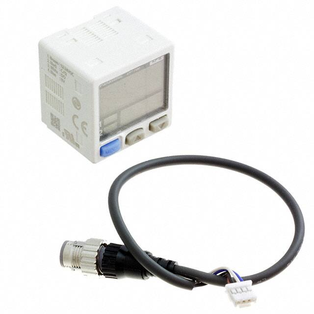


 工商网监
湘ICP备2023018690号
工商网监
湘ICP备2023018690号

