757
FIBER
SENSORS
Head-separated Dual Display Digital Pressure Sensor
For Liquid & Gas
DPC-L100 SERIES DPH-L100 SERIES
Related Information
■■General terms and conditions.............. F-7
■■Glossary of terms......................... P.1469~
■■Sensor selection guide.................. P.731~
■■General precautions....................... P.1472
LASER
SENSORS
PHOTOELECTRIC
SENSORS
Conforming to
EMC Directive
MICRO
PHOTOELECTRIC
SENSORS
AREA
SENSORS
LIGHT CURTAINS /
SAFETY
COMPONENTS
PRESSURE /
FLOW
SENSORS
INDUCTIVE
PROXIMITY
SENSORS
PARTICULAR
USE SENSORS
SENSOR
OPTIONS
SIMPLE
WIRE-SAVING
UNITS
WIRE-SAVING
SYSTEMS
MEASUREMENT
SENSORS
STATIC ELECTRICITY
PREVENTION
DEVICES
LASER
MARKERS
PLC
HUMAN MACHINE
INTERFACES
ENERGY CONSUMPTION
VISUALIZATION
COMPONENTS
FA COMPONENTS
MACHINE VISION
SYSTEMS
UV CURING
SYSTEMS
panasonic.net/id/pidsx/global
Digital
Auto reference With analog
output
High-precision detection of fluid and air pressure
Allows high-precision fluid pressure management
Compact stainless body
The analog voltage output of the sensor head can
achieve a high-precision sensing of ±1 % F.S. (at a
normal temperature of 23 °C 73.4 °F).
Compact size of HEX. 22 × 59 mm 0.866 × 2.323 in
(excluding the screws). The body is also stainless so it
can be used in various environments.
Oil-less single-layer diaphragm
59 mm 2.323 in
Oil is not encapsulated in the diaphragm of the pressure
sensing portion. No need to worry that oil will leak into
the medium when the sensor head is damaged.
Stainless diaphragm
(Integrated pressure transducer)
Main circuit
Piezo-electric
conversion
Selection
Guide
Pressure/
Digital Display
Pressure/
Head-separated
SUS630
HEX.22 mm 0.866 in
R1/4 male thread
Diaphragm: SUS630
Pressure port: SUS304
Throttle: SUSXM7
Strong against pressure surges from throttle loading
Controls pressure surges and reduces sensor failure.
Pressure port
SUS304
Flow
DPC-L100/
DPH-L100
DPS-400/
DPH-100
DPC-100/
DPH-100
Throttle
SUSXM7
Throttle
Product line
Color continuum
DPH-L113V
-0.1 to +1.0 MPa
For use with pressurized air and other media
(air mixed with water or oil)
DPH-L113
0 to +1.0 MPa
Air
Water
For use with pressurized fluid and other media
(water or chemical solutions)
DPH-L133
0 to +3.5 MPa
DPH-L114
0 to +10 MPa
Oil
For use with pressurized oil
and other media
DPH-L154
0 to +50 MPa
–0.1 0
+1
+3.5
Pressure range (MPa)
+10
+50
�Head-separated Dual Display Digital Pressure Sensor
DPC-L100 SERIES DPH-L100 SERIES
APPLICATIONS
758
FIBER
SENSORS
Transport of glass sheets after washing
(Air pressure with waterdrops)
Management of plastic filling
machine pressure
(Fluid pressure)
Management of press pressure
(Oil pressure)
LASER
SENSORS
PHOTOELECTRIC
SENSORS
MICRO
PHOTOELECTRIC
SENSORS
AREA
SENSORS
LIGHT CURTAINS /
SAFETY
COMPONENTS
PRESSURE /
FLOW
SENSORS
INDUCTIVE
PROXIMITY
SENSORS
PARTICULAR
USE SENSORS
The dual display means that the “current value” and the “threshold value”,
it makes direct setting of threshold value
Equipped with a 30 mm 1.181 in square compact-sized dual display.
Because the current value and the threshold value can be checked at the
same time, the threshold value can be set and checked smoothly without
having to switch screen modes. ON / OFF operations are still carried out
while the threshold values are being set, so setting to the same sensitivity
as dial control-type sensors is possible. And naturally a key lock function is
also equipped.
SENSOR
OPTIONS
Current value
SIMPLE
WIRE-SAVING
UNITS
WIRE-SAVING
SYSTEMS
MEASUREMENT
SENSORS
STATIC ELECTRICITY
PREVENTION
DEVICES
LASER
MARKERS
Threshold value
PLC
HUMAN MACHINE
INTERFACES
ENERGY CONSUMPTION
VISUALIZATION
COMPONENTS
3-color display (Red, Green, Orange)
Equipped with new functions optimal for fluid pressure
The main display changes color in line with changes
in the status of output ON / OFF operation, and it also
changes color while setting is in progress. The sensor
status can therefore be understood easily, and operating
errors can be reduced.
Equipped with functions optimal for fluid pressure
management while inheriting the operability of the
DP-100 series.
FA COMPONENTS
• Peak / Bottom hold 2 (output-linked)
UV CURING
SYSTEMS
Main
Display
OFF: Green (or Red)
ON: Red (or Green)
During normal operation
SET: Orange
During setting
When output turns on (or off), the controller’s digital display
(current value) is reset and peak / bottom hold operation starts.
For example, this functionality could be used to verify the
peak pressure for an industrial press each time a workpiece is
loaded.
• Current value hold
The controller’s digital display (current value) is held while
external input is on. By activating external input the moment you
wish to capture the pressure value, you can pause and verify
the display.
MOUNTING
An exclusive mounting bracket MS-DP1-2 that is suitable
for 1 to 6 mm 0.039 to 0.236 in panel thickness is
available.
Takes up
much
less space
Selection
Guide
Pressure/
Digital Display
Pressure/
Head-separated
Flow
DPC-L100/
DPH-L100
DPS-400/
DPH-100
DPC-100/
DPH-100
Tight installation to panels is possible
Tight installation is possible
MACHINE VISION
SYSTEMS
Front protection
cover available
MS-DP1-3
A single
mounting hole!
�759
FIBER
SENSORS
Head-separated Dual Display Digital Pressure Sensor
DPC-L100 SERIES DPH-L100 SERIES
PRODUCT CONFIGURATION
LASER
SENSORS
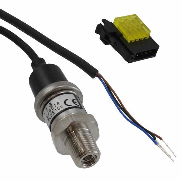
Connector (e-CON)
Sensor head
PHOTOELECTRIC
SENSORS
MICRO
PHOTOELECTRIC
SENSORS
AREA
SENSORS
PRESSURE /
FLOW
SENSORS
INDUCTIVE
PROXIMITY
SENSORS
PARTICULAR
USE
SENSORS
Sensor heads
Type
SIMPLE
WIRE-SAVING
UNITS
Compound pressure
Appearance
WIRE-SAVING
SYSTEMS
Positive pressure
STATIC
ELECTRICITY
PREVENTION
DEVICES
Rated pressure range
Model No.
-0.1 to +1.0 MPa
DPH-L113V
0 to +1.0 MPa
DPH-L113
0 to +3.5 MPa
DPH-L133
0 to +10 MPa
DPH-L114
0 to +50 MPa
DPH-L154
LASER
MARKERS
PLC
Controllers
Appearance
HUMAN
MACHINE
INTERFACES
ENERGY
CONSUMPTION
VISUALIZATION
COMPONENTS
Model No.
Comparative output
DPC-L101
NPN open-collector transistor
DPC-L101-P
PNP open-collector transistor
FA
COMPONENTS
MACHINE
VISION
SYSTEMS
UV
CURING
SYSTEMS
* CN-66A-C2
(Connector attached cable 2 m 6.562 ft) is attached.
Type without connector attached cable
Type without connector attached cable is available. When ordering this type, suffix “-J” to the Model No.
(e.g.) Type without connector attached cable of DPC-L101-P is “DPC-L101-P-J”.
Selection
Guide
Pressure/
Digital Display
Pressure/
Head-separated
Flow
DPC-L100/
DPH-L100
DPS-400/
DPH-100
DPC-100/
DPH-100
Connector attached
cable
ORDER GUIDE
SENSOR
OPTIONS
MEASUREMENT
SENSORS
Power supply
connector
Controller
LIGHT
CURTAINS /
SAFETY
COMPONENTS
Accessory
• CN-66A-C2 (Connector attached cable 2 m 6.562 ft)
Pressure port
Applicable fluid
R1/4 male thread
Gases and fluids that
do not corrode stainless
steel SUS304, SUS630,
or SUSXM7
�Head-separated Dual Display Digital Pressure Sensor
DPC-L100 SERIES DPH-L100 SERIES
OPTIONS
FIBER
SENSORS
Sensor head connector (e-CON)
Designation
Sensor head
connector
(e-CON)
Connector
attached cable
Power supply
connector
Model No.
CN-EP2 (Note 1)
5 pcs. per set
Description
••CN-EP2
MICRO
PHOTOELECTRIC
SENSORS
CN-66A-C2 (Note 2) Length 2 m 6.562 ft Controller power supply I/O cable.
CN-66A-C5
CN-66A
5 pcs. per set
0.2 mm² 6-core oil-resistant cabtyre
Length 5 m 16.404 ft cable with connector
Note: O
� ne is attached to each sensor
head according to standard.
Connector for controller power supply I/O cable.
Connector attached cable
••CN-66A-C2
••CN-66A-C5
MS-DP1-6
Allows sensors to be installed on the wall.
Multiple sensors can also be mounted closely.
Panel mounting
bracket
MS-DP1-2
Allows installation to panels with thickness of 1 to 6 mm
0.039 to 0.236 in. Multiple sensors can also be mounted closely.
MS-DP1-3
Protects the adjustment surfaces of controllers.
(Can be attached when using the panel mounting bracket)
Controller mounting bracket
••CN-66A
••MS-DP1-6
Connector pin
M3 (length 6 mm 0.236 in)
screws with washers
Accessory for
MS-DP1-6
(
Housing
LIGHT
CURTAINS /
SAFETY
COMPONENTS
PRESSURE /
FLOW
SENSORS
INDUCTIVE
PROXIMITY
SENSORS
SENSOR
OPTIONS
SIMPLE
WIRE-SAVING
UNITS
Note: �The connector attached cable CN-66A-C2
is supplied with the controller according to
standard.
Panel mounting bracket, Front protection
cover
••MS-DP1-2
••MS-DP1-3
WIRE-SAVING
SYSTEMS
MEASUREMENT
SENSORS
STATIC
ELECTRICITY
PREVENTION
DEVICES
LASER
MARKERS
PLC
)
HUMAN
MACHINE
INTERFACES
Front protection
cover
MS-DP1-3
Controller
mounting
bracket
MS-DP1-6
(Optional)
AREA
SENSORS
PARTICULAR
USE
SENSORS
Notes: 1) One is attached to each sensor head according to standard.
2) �The connector attached cable CN-66A-C2 is supplied with the controller according to standard.
Power supply connector
LASER
SENSORS
PHOTOELECTRIC
SENSORS
Connector for connecting sensor head controller
Controller mounting
bracket
Front protection
cover
760
ENERGY
CONSUMPTION
VISUALIZATION
COMPONENTS
FA
COMPONENTS
Panel mounting bracket
MS-DP1-2
MACHINE
VISION
SYSTEMS
UV
CURING
SYSTEMS
Recommended e-CON
Model No.: 1473562-4 (Manufactured by Tyco Electronics Japan G.K.)
Note: Contact the manufacturer for details of the recommended products.
Recommended power supply connector
Contact: SPHD-001T-P0.5, Housing: PAP-06V-S (Manufactured by J.S.T. Mfg. Co., Ltd.)
Note: Contact the manufacturer for details of the recommended products.
Recommended crimping tool
Model No.: YC-610R (Manufactured by J.S.T. Mfg. Co., Ltd.)
Note: Contact the manufacturer for details of the recommended products.
Selection
Guide
Pressure/
Digital Display
Pressure/
Head-separated
Flow
DPC-L100/
DPH-L100
DPS-400/
DPH-100
DPC-100/
DPH-100
�761
Head-separated Dual Display Digital Pressure Sensor
SPECIFICATIONS
FIBER
SENSORS
LASER
SENSORS
Sensor heads
PHOTOELECTRIC
SENSORS
MICRO
PHOTOELECTRIC
SENSORS
AREA
SENSORS
LIGHT
CURTAINS /
SAFETY
COMPONENTS
PRESSURE /
FLOW
SENSORS
INDUCTIVE
PROXIMITY
SENSORS
PARTICULAR
USE
SENSORS
Type
Item
Model No.
Compound pressure
Positive pressure
-0.1 to 1 MPa type
1 MPa type
3.5 MPa type
10 MPa type
50 MPa type
DPH-L113V
DPH-L113
DPH-L133
DPH-L114
DPH-L154
-0.1 to +1 MPa
0 to +1 MPa
0 to +3.5 MPa
0 to +10 MPa
0 to +50 MPa
2 MPa
7 MPa
20 MPa
75 MPa
Type of pressure
Rated pressure range
Pressure withstandability
Sealed gauge pressure (Note 4)
2 MPa
Applicable fluid
Gases and fluids that do not corrode SUS630, SUS304, or SUSXM7
Supply voltage
9 to 36 V DC
[9 to 32 V DC when using the attached connector (e-CON)]
Current consumption
Analog voltage output
SENSOR
OPTIONS
SIMPLE
WIRE-SAVING
UNITS
DPC-L100 SERIES DPH-L100 SERIES
20 mA or less
Output voltage: 1 to 5 V DC (over rated pressure range)
Accuracy: �±1.0 % F.S. (at 23 ±2 °C +73.4 ±35 °F)
±2.0 % F.S. (at -20 to 70 °C -4 to +158 °F)
(including linearity, hysteresis and repeatability)
Response time
1 ms or less
Protection
IP67 (IEC)
STATIC
ELECTRICITY
PREVENTION
DEVICES
LASER
MARKERS
PLC
HUMAN
MACHINE
INTERFACES
ENERGY
CONSUMPTION
VISUALIZATION
COMPONENTS
FA
COMPONENTS
MACHINE
VISION
SYSTEMS
UV
CURING
SYSTEMS
Environmental resistance
WIRE-SAVING
SYSTEMS
MEASUREMENT
SENSORS
Ambient temperature
-20 to +70 °C -4 to +158 °F (No dew condensation allowed),
Storage: -30 to +70°C -22 to +158 °F
Ambient humidity
-20 to +70 °C -4 to +158 °F
Voltage withstandability
150 V AC for one min. between all supply terminals connected together and enclosure
100 MΩ, or more, with 50 V DC megger between all supply terminals connected together and enclosure
Vibration resistance
10 to 2,000 Hz frequency, acceleration 200 m/s2, in X di‑rection for four hours, in Y and Z directions for two hours each (Note 5)
Shock resistance
1,000 m/s2 acceleration in X, Y and Z directions for three times each
Grounding method
Capacitor earth (Enclosure-supply terminal)
Pressure port
Material
R1/4 male thread (throttle embeded)
Diaphragm: Stainless steel (SUS630), Pressure port: Stainless steel (SUS304), Throttle: Stainless steel (SUSXM7)
Connecting method
Connector
Cable
0.2 mm2 3-core heat resistant cabtyre cable 2 m 3.562 ft long
Extension up to total 10 m 32.808 ft is possible with 0.2 mm2, or more, cable.
Net weight: 100 g approx., Gross weight: 150 g approx.
Accessory
Pressure/
Head-separated
Connector (e-CON): 1 pc.
Notes: 1) Where measurement conditions have not been specified precisely, the conditions used were an ambient temperature of +23 °C +73.4 °F.
2) The sensor head can be used independently.
3) Oil is used in the factory inspection process for models DPH-L114 and DPH-L154. There may be some residual oil inside the pressure port.
4) The sensor’s internal mechanism is sealed based on an air pressure of 1,013 hPa.
5) The X, Y, and Z directions are defined as follows:
Flow
DPC-L100/
DPH-L100
DPS-400/
DPH-100
DPC-100/
DPH-100
-20 to +125 °C -4 to +257 °F
Insulation resistance
Weight
Pressure/
Digital Display
-20 to +80 °C -4 to +176 °F (Pressure port: -20
to +125 °C -4 to +257 °F, No dew condensation
allowed),Storage: -30 to +100 °C -22 to +212 °F
e-CON connector (accesory): -20 to +75 °C
-4 to +167 °F
(Storage: -30 to +75 °C -22 to +167 °F)
35 to 85 % RH, Storage: 35 to 85 % RH
Medium temperature range
Cable extension
Selection
Guide
Output voltage: 1 to 5 V DC (over rated pressure range)
Accuracy: �±1.0 % F.S. (at 23 ±2 °C +73.4 ±35 °F)
±2.0 % F.S. (at -20 to 125 °C -4 to +158 °F)
(including linearity, hysteresis and repeatability)
X
Z
Y
�Head-separated Dual Display Digital Pressure Sensor
DPC-L100 SERIES DPH-L100 SERIES
SPECIFICATIONS
FIBER
SENSORS
LASER
SENSORS
Model No.
Controllers
Item
DPC-L101
NPN output
Rated pressure range
Set pressure range
Set resolution
Display
Displayable pressure range
Supply voltage
Power consumption
Comparative outputs
(Comparative output 1, 2)
DPH-L113V
DPH-L113
Hysteresis
Inputs
Sensor head input
External input
DPH-L154
0 to +1 MPa
0 to +3.5 MPa
0 to +10 MPa
0 to +50 MPa
-1.070 to +1.070 MPa
-10.91 to +10.91 kgf/cm²
-10.70 to +10.70 bar
-155.2 to +155.2 psi
-3.74 to +3.74 MPa
-38.1 to +38.1 kgf/cm²
-37.4 to +37.4 bar
-542 to +542 psi
-10.70 to +10.70 MPa
-109.1 to +109.1 kgf/cm²
-107.0 to +107.0 bar
-1552 to +1552 psi
-53.5 to +53.5 MPa
-545 to +545 kgf/cm²
-535 to +535 bar
-1980 to +7760 psi
0.001 MPa
0.001 MPa
0.01 MPa
0.01 MPa
0.1 MPa
4 digits +4 digits 3-color LCD display (Display refresh rate: 250 ms, 500 ms, 1,000 ms, selectable by key operation)
-0.155 to +1.022 MPa
-1.58 to +10.42 kgf/cm²
-1.55 to +10.22 bar
-22.4 to +148.2 psi
-0.050 to +1.020 MPa
-0.51 to +10.40 kgf/cm²
-0.50 to +10.20 bar
-7.2 to +148.0 psi
-0.17 to +3.57 MPa
-1.7 to +36.4 kgf/cm²
-1.7 to +35.7 bar
-24 to +518 psi
-0.50 to +10.20 MPa
-5.1 to +104.0 kgf/cm²
-5.0 to +102.0 bar
-72 to +1480 psi
-2.5 to +51.0 MPa
-25 to +520 kgf/cm²
-25 to +510 bar
-360 to +7400 psi
12 to 24 V DC ±10 % Ripple P-P 10 % or less
Normal operation: 960 mW or less (Current consumption 40 mA or less at 24 V supply voltage)
ECO mode (STD): 720 mW or less (Current consumption 30 mA or less at 24 V supply voltage)
ECO mode (FULL): 600 mW or less (Current consumption 25 mA or less at 24 V supply voltage)
Excluding the current consumption of sensor head and analog output current
NPN open-collector transistor (2 outputs)
• Maximum sink current: 50 mA
• Applied voltage: 30 V DC or less
(between comparative output and 0 V)
• Residual voltage: 1 V or less (at 50 mA sink current)
PNP open-collector transistor (2 outputs)
• Maximum source current: 50 mA
• Applied voltage: 30 V DC or less
(between comparative output and +V)
• Residual voltage: 1 V or less (at 50 mA source current)
Minimum 1 digit (variable) (however, 2 digits when using psi unit)
Within ±0.2 % F.S.
5 ms, 10 ms, 25 ms, 50 ms, 100 ms, 250 ms, 500 ms, 1,000 ms, 5,000 ms, selectable by key operation
Incorporated
• Output current: 1 to 5 V DC
• Zero point: �within 1 V ±0.5 % F.S.
(excluding DPH-L113V)
within 1.364 V ±0.5 % F.S. (DPH-L113V)
• Span: within 4 V ±0.5 % F.S.
• Linearity: within ±0.1 % F.S.
• Output impedance: 1 kΩ approx.
• Output current: 4 to 20 mA
• Zero point: �within 4 mA ±1.0 % F.S.
(excluding DPH-L113V)
within 5.455 mA ±1.0 % F.S. (DPH-L113V)
• Span: within 16 mA ±1.5 % F.S.
• Linearity: within ±0.1 % F.S.
• Load resistance: 250 Ω (max.)
Input voltage range: 1 to 5 V DC (over rated pressure range)
ON voltage: 0.4 V DC or less
OFF voltage: 5 to 30 V DC, or open
Input impedance: 10 kΩ approx.
Input time: 1 ms or more
Environmental resistance
Vibration resistance
Shock resistance
Temperature characteristics
Material
Connecting method
Weight
Accessories
INDUCTIVE
PROXIMITY
SENSORS
PARTICULAR
USE
SENSORS
SENSOR
OPTIONS
SIMPLE
WIRE-SAVING
UNITS
WIRE-SAVING
SYSTEMS
MEASUREMENT
SENSORS
PLC
HUMAN
MACHINE
INTERFACES
ENERGY
CONSUMPTION
VISUALIZATION
COMPONENTS
FA
COMPONENTS
MACHINE
VISION
SYSTEMS
UV
CURING
SYSTEMS
ON voltage: 5 V to +V DC
OFF voltage: 0.6 V DC or less, or open
Input impedance: 10 kΩ approx.
Input time: 1 ms or more
IP40 (IEC)
Insulation resistance
PRESSURE /
FLOW
SENSORS
LASER
MARKERS
Orange LED (Comparative output 1 operation indicator, comparative output 2 operation indicator: Lights up when each comparative output is ON )
Voltage withstandability
LIGHT
CURTAINS /
SAFETY
COMPONENTS
EASY mode / Hysteresis mode / Window comparator mode
Protection
Ambient humidity
AREA
SENSORS
NO / NC, selectable by key operation
Operation indicator
Ambient temperature
MICRO
PHOTOELECTRIC
SENSORS
STATIC
ELECTRICITY
PREVENTION
DEVICES
Short-circuit protection
Analog output
DPH-L114
-0.1 to +1 MPa
Repeatability
Response time
DPH-L133
-1.177 to +1.177 MPa
-12.00 to +12.00 kgf/cm²
-11.77 to +11.77 bar
-170.6 to +170.6 psi
Output operation
Output modes
PHOTOELECTRIC
SENSORS
DPC-L101-P
PNP output
Applicable sensor head
Cable length
762
-10 to +50 °C +14 to +122 °F (No dew condensation or icing allowed), Storage: -10 to +60 °C +14 to +140 °F
35 to 85 % RH, Storage: 35 to 85 % RH
500 V AC for one min. between all supply terminals connected together and enclosure
50 MΩ, or more, with 500 V DC megger between all supply terminals connected together and enclosure
10 to 500 Hz frequency, amplitude 3 mm 0.118 in or maximum acceleration 196 m/s2, in X, Y and Z directions for two hours each (when panel mounting
bracket is mounted: 10 to 150 Hz frequency, amplitude 0.75 mm 0.030 in or maximum acceleration 49 m/s2, in X, Y and Z directions for two hours each)
100 m/s2 acceleration in X, Y and Z directions for three times each
Within ±0.5 % F.S. (ambient temperature range based on +20 °C +68 °F)
Enclosure: PBT (glass fiber reinforced), LCD display: Acrylic, Mounting threaded part: Brass (nickel plated), Switch part: Silicone rubber
Connector
Total length up to 100 m 328.1 ft (less than 30 m 98.4 ft when conforming to CE marking) is possible with 0.3 mm2, or more, cable.
Net weight: 25 g approx. (excluding connector attached cable), Gross weight: 140 g approx.
CN-66A-C2 (Connector attached cable 2 m 6.562 ft), Pressure unit label: 1 set
Notes: 1) Where measurement conditions have not been specified precisely, the conditions used were an ambient temperature of +20 °C +68 °F.
2) The values specified above are applied only to the controller.
Selection
Guide
Pressure/
Digital Display
Pressure/
Head-separated
Flow
DPC-L100/
DPH-L100
DPS-400/
DPH-100
DPC-100/
DPH-100
�763
Head-separated Dual Display Digital Pressure Sensor
I/O CIRCUIT AND WIRING DIAGRAMS
FIBER
SENSORS
DPC-L101
I/O circuit diagram
CN2 terminal No.
MICRO
PHOTOELECTRIC
SENSORS
LIGHT
CURTAINS /
SAFETY
COMPONENTS
PRESSURE /
FLOW
SENSORS
INDUCTIVE
PROXIMITY
SENSORS
Sensor head
internal circuit
10kΩ D 2
1kΩ
D3
Tr1
ZD1
ZD2
Tr2
(Brown) +V
(Pink) External *1
input
(Gray) Analog
voltage / current output
Load
(Note 1,2)
Load +
(Black) Comparative
output 1
–
50 mA max.
(White)
Comparative output 2
(Blue) 0 V
Controller internal circuit
Intermediate cable
Terminal No.
Color code
(Brown) +V
12 to 24 V DC
±10 %
50 mA max.
User’s circuit
Notes: 1) Set the output load resistance during analog current output to 250 Ω (max.).
2) Note that a voltage of 5 V or higher is generated during analog current output.
SIMPLE
WIRE-SAVING
UNITS
Sensor head
internal circuit
*1
Non-voltage contact or NPN open-collector transistor
STATIC
ELECTRICITY
PREVENTION
DEVICES
or
LASER
MARKERS
High (5 to 30 V DC, or open): Invalid
Low (0.4 V DC or less): Valid
PLC
(Black) Analog
voltage output
(1 to 5 V)
+
–
9 to 36 V DC
(Blue) 0 V
User’s circuit
Notes: 1) �When the sensor head is used
independently, devices connected to
the analog output must have an input
impedance set at 10 kΩ or more and
load capacity 1,000 pF or less.
2) �No short-circuit protection circuit is
provided for analog voltage output.
Do not connect directly to a power
supply.
3) �The pressure port and internal circuitry
are connected by a capacitor.
Do not apply voltage in excess of
the specifications’ dielectric strength
between the pressure port and wiring.
4) �The transparent tube attached to the
cable is not used and should be cut off
at the base.
Symbols …D1 to D3 : Reverse supply polarity protection diode
ZD1, ZD2 : Surge absorption zener diode
Tr1, Tr2 : NPN output transistor
WIRE-SAVING
SYSTEMS
MEASUREMENT
SENSORS
Unused
0V
PARTICULAR
USE
SENSORS
SENSOR
OPTIONS
Color code of connector attached cable
D1
Analog
voltage
input
For independent use of sensor head
CN1 terminal No.
+V
Sensor head main circuit
AREA
SENSORS
NPN output type
Sensor head main circuit
PHOTOELECTRIC
SENSORS
Controller main circuit
LASER
SENSORS
DPC-L100 SERIES DPH-L100 SERIES
HUMAN
MACHINE
INTERFACES
ENERGY
CONSUMPTION
VISUALIZATION
COMPONENTS
I/O circuit diagram
Pressure/
Head-separated
Flow
DPC-L100/
DPH-L100
DPS-400/
DPH-100
DPC-100/
DPH-100
For independent use of sensor head
Color code of connector attached cable
+V
Terminal No.
(Brown) +V
Sensor head main circuit
Pressure/
Digital Display
CN1 terminal No.
CN2 terminal No.
UV
CURING
SYSTEMS
Selection
Guide
PNP output type
Unused
Analog
voltage
input
0V
Sensor head
internal circuit
Intermediate cable
D1
Tr1
10kΩ D2
ZD1
Tr2
ZD2
1kΩ
D3
(Pink) External
*1
input
(Black) Comparative
50 mA max.
output 1
(White) Comparative
50 mA max.
output 2
(Gray) Analog
voltage / current output
(Note 1, 2)
(Blue) 0 V
Controller internal circuit
Color code
(Brown) +V
+
–
Load
Load
User’s circuit
Notes: 1) Set the output load resistance during analog current output to 250 Ω (max.).
2) Note that a voltage of 5 V or higher is generated during analog current output.
Symbols …D1 to D3 : Reverse supply polarity protection diode
ZD1, ZD2 : Surge absorption zener diode
Tr1, Tr2 : PNP output transistor
*1
Non-voltage contact or PNP open-collector transistor
or
High (5 to +V DC, or open): Invalid
Low (0.6 V DC or less, or open): Valid
12 to 24 V DC
±10 %
Sensor head main circuit
MACHINE
VISION
SYSTEMS
DPC-L101-P
Controller main circuit
FA
COMPONENTS
Sensor head
internal circuit
(Black) Analog
voltage output
(1 to 5 V)
+
–
9 to 36 V DC
(Blue) 0 V
User’s circuit
Notes: 1) �When the sensor head is used
independently, devices connected to
the analog output must have an input
impedance set at 10 kΩ or more and
load capacity 1,000 pF or less.
2) �No short-circuit protection circuit is
provided for analog voltage output.
Do not connect directly to a power
supply.
3) �The pressure port and internal circuitry
are connected by a capacitor.
Do not apply voltage in excess of
the specifications’ dielectric strength
between the pressure port and wiring.
4) �The transparent tube attached to the
cable is not used and should be cut off
at the base.
�Head-separated Dual Display Digital Pressure Sensor
DPC-L100 SERIES DPH-L100 SERIES
764
I/O CIRCUIT AND WIRING DIAGRAMS
FIBER
SENSORS
LASER
SENSORS
Terminal arrangement diagram
1
2
3
4
5
6
Connector for power supply
I/O cable connection
Connector for power supply I/O cable (CN1)
Connector for sensor head (CN2)
1 +V
2 Analog voltage / current output
3 0 V
4 Comparative output 1
5 Comparative output 2
6 External input
auto-reference function / remote zero-adjustment
function / current value hold function)
1 Sensor head supply voltage
2 Analog voltage input
3 0 V
4 Unused
2
3
MICRO
PHOTOELECTRIC
SENSORS
AREA
SENSORS
LIGHT
CURTAINS /
SAFETY
COMPONENTS
PRESSURE /
FLOW
SENSORS
Connector for sensor
head connection
1
PHOTOELECTRIC
SENSORS
INDUCTIVE
PROXIMITY
SENSORS
4
PARTICULAR
USE
SENSORS
PRECAUTIONS FOR PROPER USE
• Never use this product as a sensing device
for personnel protection.
• In case of using sensing devices for
personnel protection, use products which
meet laws and standards, such as OSHA,
ANSI or IEC etc., for personnel protection
applicable in each region or country.
• The DPH-L100 series is designed for use with
air and non-corrosive gas. It cannot be used
with liquid or corrosive and inflammable gases.
Part description
Main display
Output 1 operation indicator
Output 2 operation indicator
Sub display
Refer to p.1472 for general precautions.
Others
• Never remove the throttle.
• Use within the rated pressure range.
• Do not apply pressure exceeding the pressure
withstandability value. The diaphragm will get damaged
and correct operation shall not be maintained.
• Do not use during the initial transient time (controller: 0.5
sec. approx, sensor head: 50 ms approx.) after the power
supply is switched on.
• Avoid dust, dirt, and steam.
• Take care that the sensor does not come in direct
contact with water, oil, grease, or organic solvents, such
as, thinner, etc.
• Do not insert wires, etc., into the pressure port. The
diaphragm will get damaged and correct operation shall
not be maintained.
• Do not operate the keys with pointed or sharp objects.
SENSOR
OPTIONS
SIMPLE
WIRE-SAVING
UNITS
WIRE-SAVING
SYSTEMS
MEASUREMENT
SENSORS
STATIC
ELECTRICITY
PREVENTION
DEVICES
LASER
MARKERS
PLC
HUMAN
MACHINE
INTERFACES
ENERGY
CONSUMPTION
VISUALIZATION
COMPONENTS
FA
COMPONENTS
MACHINE
VISION
SYSTEMS
UV
CURING
SYSTEMS
Mode selection key
Set value DOWN key
Set value UP key
Wiring
• Make sure that the power supply is off while wiring.
• Verify that the supply voltage variation is within the
rating.
• If power is supplied from a commercial switching
regulator, ensure that the frame ground (F.G.) terminal of
the power supply is connected to an actual ground.
• In case noise generating equipment (switching regulator,
inverter motor, etc.) is used in the vicinity of this
sensor, connect the frame ground (F.G.) terminal of the
equipment to an actual ground.
• Do not run the wires together with high-voltage lines or
power lines or put them in the same raceway. This can
cause malfunction due to induction.
• Incorrect wiring will cause problems with operation.
Selection
Guide
Pressure/
Digital Display
Pressure/
Head-separated
Flow
DPC-L100/
DPH-L100
DPS-400/
DPH-100
DPC-100/
DPH-100
�765
FIBER
SENSORS
LASER
SENSORS
Head-separated Dual Display Digital Pressure Sensor
DIMENSIONS (Unit: mm in)
Sensor head
22
0.866
MICRO
PHOTOELECTRIC
SENSORS
14
6
0.551 0.236
73
(2.874
)
18.5
12
(0.728
) (0.472
)
11.5 0.453
AREA
SENSORS
(0.924.3
57 )
LIGHT
CURTAINS /
SAFETY
COMPONENTS
INDUCTIVE
PROXIMITY
SENSORS
The CAD data in the dimensions can be downloaded from our website.
DPH-L1□
PHOTOELECTRIC
SENSORS
PRESSURE /
FLOW
SENSORS
DPC-L100 SERIES DPH-L100 SERIES
ø0.7 ø0.028
throttle
R1/4
male thread
ø20
ø0.787
ø20
ø0.787
Cap
ø25
ø0.984
ø4.3 ø0.169 cable 2 m 6.562 ft long
3-core × 0.2 mm2
insulator diameter: ø1.0 ø0.039
DPC-L101(-P)
Controller
15.8
0.622
PARTICULAR
USE
SENSORS
7.9
0.311
SENSOR
OPTIONS
SIMPLE
WIRE-SAVING
UNITS
WIRE-SAVING
SYSTEMS
30
1.181
25.6
1.008
MEASUREMENT
SENSORS
STATIC
ELECTRICITY
PREVENTION
DEVICES
FA
COMPONENTS
MACHINE
VISION
SYSTEMS
3.8
0.150
Pressure/
Digital Display
Pressure/
Head-separated
Flow
DPC-L100/
DPH-L100
DPS-400/
DPH-100
DPC-100/
DPH-100
9.05
0.356
1.5
0.059
MS-DP1-6
Controller mounting bracket (Optional)
Assembly dimensions
9.5
0.374
(R)
14.5
0.571
4.2
0.165
21
0.827
4.2
0.165
14.5
0.571
(R)
9.5 25.5
0.374 1.004
21
0.827
UV
CURING
SYSTEMS
Selection
Guide
18
0.709
2-M3 female thread,
4 0.157 deep
8.9
0.350
7.3
0.287
PLC
ENERGY
CONSUMPTION
VISUALIZATION
COMPONENTS
20
0.787
6.4
0.252
20.2
30 0.795
1.181
LASER
MARKERS
HUMAN
MACHINE
INTERFACES
3.7
0.146
25.5
1.004
20
0.787
2-ø3.5 ø0.138
mounting hole
2
0.079
34.3 30
1.350 1.181
10.5
0.413
45
( 1.772
)
10
0.394
18
0.709
29.95
1.179
Material: Cold rolled carbon steel (SPCC)
(Trivalent uni-chrome plated)
Two M3 (length 6 mm 0.236 in) screws with
washers are attached.
8.9
0.350
30
( 1.181
)
30
1.181 45
1.772
1.5
0.059
30
1.181
3.7
0.146
30
1.181
2
0.079
9.05
0.356
6.4
0.252
15.8
0.622
�Head-separated Dual Display Digital Pressure Sensor
DPC-L100 SERIES DPH-L100 SERIES
DIMENSIONS (Unit: mm in)
766
The CAD data in the dimensions can be downloaded from our website.
MS-DP1-2 MS-DP1-3
Panel mounting bracket (Optional), Front protection cover (Optional)
Mounting drawing with DPC-L101(-P)
Vertical mounting
MICRO
PHOTOELECTRIC
SENSORS
Horizontal mounting
15.8
0.622
Panel mounting bracket
(
)
(
)
7.2
0.283
(
34.5
1.358
)
20
0.787
6
0.236
8.7
0.343
33.4
1.315
24
0.945
18.3
0.720
(
PRESSURE /
FLOW
SENSORS
)
11
0.433
INDUCTIVE
PROXIMITY
SENSORS
)
39.3
1.547
34.5
1.358
3.7
0.146
6.4
0.252
A
)
20
0.787
3.7
0.146
PARTICULAR
USE
SENSORS
SENSOR
OPTIONS
6.4
0.252
6
0.236
A
8.7
0.343
50
1.969
33.4
1.315
Panel thickness dimension
1 to 6 0.039 to 0.236
18.3
0.720
7.2
0.283
(
34.5
1.358
Panel thickness dimension
1 to 6 0.039 to 0.236
52
2.047
max.
M3 female thread,
4 0.157deep
52
2.047
max.
9.05
0.356
9.05
0.356
HUMAN
MACHINE
INTERFACES
ENERGY
CONSUMPTION
VISUALIZATION
COMPONENTS
View A
Panel cut-out dimensions
When 1 unit is installed
When “n” units are installed horizontally in series
When “n” units are installed vertically in series
−0
31−0.4
−0
−0
31−0.4
−0
1.220 −0.016
55 2.165
or more
−0
31−0.4
−0
1.220 −0.106
CN-66A-C2 CN-66A-C5
35
(1.378
)
UV
CURING
SYSTEMS
31 1.220 × n +
3.5 0.138 × (n-1)
Note: �The panel thickness should be
1 to 6 mm 0.039 to 0.236 in.
(0.3158 )
FA
COMPONENTS
MACHINE
VISION
SYSTEMS
−0
1.220−0.016
31 1.220 × n + 3.5 0.138 × (n-1)
31−0.4
−0
1.220 −0.106
MEASUREMENT
SENSORS
PLC
( )
View A
WIRE-SAVING
SYSTEMS
LASER
MARKERS
33.4
1.315
( )
SIMPLE
WIRE-SAVING
UNITS
STATIC
ELECTRICITY
PREVENTION
DEVICES
8.9
0.350
8.9
0.350
50 33.4
1.969 1.315
LIGHT
CURTAINS /
SAFETY
COMPONENTS
Front protection cover
Front protection cover
(
AREA
SENSORS
Panel mounting bracket
11
0.433
39.3
1.547
34.5
1.358
LASER
SENSORS
PHOTOELECTRIC
SENSORS
Assembly dimensions
15.8
0.622
FIBER
SENSORS
55 2.165
or more
Note: The panel thickness should be 1 to 6 mm 0.039 to 0.236 in.
Connector attached cable (Optional, CN-66A-C2 is attached to the controller)
Pressure/
Digital Display
Pressure/
Head-separated
Flow
• Length L
L
50
(1.969
)
Selection
Guide
( )
8
0.315
ø4.8 ø0.189 cable
6-core × 0.2 mm2
insulator diameter: ø1.2 ø0.047
Model No.
Length L
CN-66A-C2
2,000 78.740
CN-66A-C5
5,000 196.850
DPC-L100/
DPH-L100
DPS-400/
DPH-100
DPC-100/
DPH-100
�