DS2Y
Miniature relay
DS2Y RELAYS
FEATURES
TYPICAL APPLICATIONS
1. 2 Form C contact
2. High sensitivity-200 mW nominal
operating power
3. High breakdown voltage
1500 V FCC surge between open
contacts
4. DIP-2C type matching 16 pin IC
socket
5. Sealed construction
6. Sealed according to RTIII (IP67)
1. Telecommunication equipment
2. Office equipment
3. Computer peripherals
4. Security alarm systems
5. Medical equipment
ORDERING INFORMATION
DS2Y-S
Operating function
Nil: Single side stable
Nominal coil voltage
DC 1.5, 3, 5, 6, 9, 12, 24, 48 V
Polarity
Nil: Standard polarity
Note: UL/CSA approved type is standard.
TYPES
Contact arrangement
Nominal coil voltage
2 Form C
1.5V DC
3V DC
5V DC
6V DC
9V DC
12V DC
24V DC
48V DC
Single side stable type
Part No.
DS2Y-S-DC1.5V
DS2Y-S-DC3V
DS2Y-S-DC5V
DS2Y-S-DC6V
DS2Y-S-DC9V
DS2Y-S-DC12V
DS2Y-S-DC24V
DS2Y-S-DC48V
Standard packing: Tube: 50 pcs.; Case: 500 pcs.
ds_61005_en_ds2y: 280114D
1
�DS2Y
RATING
1. Coil data
Single side stable type
Nominal operating
current
[10%] (at 20C 68F)
Coil resistance
[10%] (at 20C 68F)
1.5V DC
132.7mA
11.3
3V DC
5V DC
6V DC
9V DC
12V DC
24V DC
48V DC
66.7mA
40mA
33.3mA
22.2mA
16.7mA
8.3mA
6.3mA
45
125
180
405
720
2,880
7,680
Nominal coil
voltage
Pick-up voltage
(at 20C 68F)
70%V or less of
nominal voltage
(Initial)
Drop-out voltage
(at 20C 68F)
10%V or more of
nominal voltage
(Initial)
Nominal operating
power
Max. applied voltage
(at 50C 122F)
200mW
200%V of
nominal voltage
300mW
2. Specifications
Characteristics
Contact
Rating
Item
Arrangement
Initial contact resistance, max.
Contact material
Max. switching power
Max. switching voltage
Max. switching current
Max. carrying current
Minimum operating power
Nominal operating power
Specifications
2 Form C
Max. 50 m (By voltage drop 6 V DC 1A)
Ag+Au clad
60 W, 62.5 VA (resistive load)
220 V DC, 250 V AC
2A
3A
Approx. 98 mW (147 mW: 48 V)
Approx. 200 mW (300 mW: 48 V)
Insulation resistance (Initial)
Min. 100M (at 500V DC)
Measurement at same location as “Initial breakdown voltage” section.
Between open contacts
Between contact sets
Between contact and coil
FCC surge breakdown voltage between contacts
and coil
Temperature rise (at 20C 68F)
Breakdown voltage
(Initial)
Electrical
characteristics
Operate time [Set time] (at 20C 68F)
Release time [Reset time] (at 20C 68F)
Functional
Destructive
Functional
Vibration resistance
Destructive
Mechanical
Electrical
Shock resistance
Mechanical
characteristics
Expected life
Conditions
Conditions for operation, transport and storage*
Max. operating speed (at rated load)
Unit weight
750 Vrms for 1min. (Detection current: 10mA.)
1,000 Vrms for 1min. (Detection current: 10mA.)
1,000 Vrms for 1min. (Detection current: 10mA.)
1,500 V
Max. 65C with nominal coil voltage across coil and at nominal switching capacity
Approx. 4 ms [approx. 3 ms]
(Nominal coil voltage applied to the coil, excluding contact bounce time.)
Approx. 3 ms [approx. 3 ms]
(Nominal coil voltage applied to the coil, excluding contact bounce time.) (without diode)
Min. 490 m/s2 (Half-wave pulse of sine wave: 11 ms; detection time: 10s.)
Min. 980 m/s2 (Half-wave pulse of sine wave: 6 ms.)
10 to 55 Hz at double amplitude of 3.3 mm (Detection time: 10s.)
10 to 55 Hz at double amplitude of 5 mm
Min. 108
5105 (1 A 30 V DC), 105 (2 A 30 V DC)
Ambient temperature: –40C to +70C –40F to +158F
Humidity: 5 to 85% R.H. (Not freezing and condensing at low temperature)
60 times/min.
Approx. 4g .14oz
* Refer to “6. Usage, Storage and Transport Conditions“ in AMBIENT ENVIRONMENT section in Relay Technical Information.
2
ds_61005_en_ds2y: 280114D
�DS2Y
REFERENCE DATA
1. Maximum switching capacity
2. Coil temperature rise (Single side stable)
3. Operate/release time for single side stable
(Without diode)
Tested sample: DS2Y-S-DC12V, 5 pcs.
Measured portion: Inside the coil
Ambient temperature: 21C to 25C 70F to 77F
Tested sample: DS2Y-S-DC12V, 10 pcs.
Ambient temperature: 20C 68F
1,000 V
5
Operate time
Release time
100 V
10 V
4
2A
Time, ms
Temperature rise, °C
Contact voltage
3A
30
0A
3
Mean value
Mean value
2
20
1
10 mA
10 µA
100 mA
100
1A
Switching current
110
Coil applied voltage, %V
0
4-(2) Influence of adjacent mounting
Tested sample: DS2Y-S-DC12V, 10 pcs.
Ambient temperature: 20C 68F
Tested sample: DS2Y-S-DC12V, 10 pcs.
Ambient temperature: 20C 68F
TEST METHOD
1. Apply nominal voltage to No. (1) and (3) DS2Y
relays.
2. Measure pick-up voltage and drop-out voltage of
No. (2) relay when inter-relay distance ( ) changes.
TEST METHOD
1. Apply nominal voltage to No. (1) and (3) DS2Y
relays.
2. Measure pick-up voltage and drop-out voltage of
No. (2) relay when inter-relay distance ( ) changes.
(1)
OFF
10
(2)
(3)
OFF
Pick-up/Drop-out voltage, V
Pick-up/Drop-out voltage, V
4-(1) Influence of adjacent mounting
8
ON
ON
Pick-up voltage
6
OFF
OFF
4
Drop-out voltage
ON
ON
2
0
80
100
120
Coil applied voltage, %V
10
(1)
OFF
(2)
(3)
OFF
8
Pick-up voltage
ON
ON
OFF
OFF
ON
ON
6
4
Drop-out voltage
2
0
5
10
15
.197 .394 .591
Inter-relay distance, mm inch
5
10
15
.197 .394 .591
Inter-relay distance, mm inch
DIMENSIONS (mm inch)
CAD Data
Data from our Web site.
Download CAD
Single side stable
CAD Data External dimensions
PC board pattern (Copper-side view)
(Deenergized position)
8-0.9 dia.
8-.035 dia.
9.9
.390
20
.787
2.54
.100
9.3
.366
5.08 5.08
.200 .200
7.62
.300
2.0
.078
0.6
.024
5.6
.220
7.62
.300
9
11
13
N.O. N.C. COM
16
–
N.O. N.C. COM
8
6
4
+
1
2.54
.100
0.6
.024
0.6
.024
Schematic (Bottom view)
3.4
.134
7.62
.300
0.3
.012
matching 16 pin IC socket
Tolerance: 0.1 .004
Direction indication*
*A polarity bar shows the relay direction.
General tolerance: 0.3 .012
For Cautions for Use, see Relay Technical Information.
ds_61005_en_ds2y: 280114D
3
�
很抱歉,暂时无法提供与“DS2Y-SL2-DC6V”相匹配的价格&库存,您可以联系我们找货
免费人工找货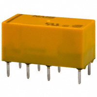


 工商网监
湘ICP备2023018690号
工商网监
湘ICP备2023018690号
