0
登录后你可以
  • 下载海量资料
  • 学习在线课程
  • 观看技术视频
  • 写文章/发帖/加入社区
会员中心
创作中心
发布
  • 发文章

  • 发资料

  • 发帖

  • 提问

  • 发视频

创作活动
ECC-T3F180JG

ECC-T3F180JG

  • 厂商:

    NAIS(松下)

  • 封装:

    SMD

  • 描述:

    贴片电容(MLCC) Nonstandard SMD 18pF ±5% 3KV SL/GP

  • 详情介绍
  • 数据手册
  • 价格&库存
ECC-T3F180JG 数据手册
High Voltage Ceramic Capacitors (SMD) High Voltage Ceramic Capacitors For Surface Mounting Discontinued 1 to 5 kVDC ■ Features ■ Recommended Application ● Resin molded SMD type for reflow solderings ● High reliability through use of disc capacitor element ● Wide rated voltage ranges from 1 kV to 5 kV, through a disc element which withstand high voltage and outcurve terminals ● Wide rated voltage range 1 to 5 kV ● Ballast circuit of LCD backlighting inverter (For 3 to 5 kVDC Char.SL/GP) ● Snubber circuit of switching power supply (For 1 to 2 kVDC Char.B/Y5P) ■ Explanation of Part Numbers 1 2 3 4 5 6 7 8 9 10 11 E C C T 3 F 4 7 0 J G Product Code Code Class ECC Class1 ECK Class2 Packaging Style Code Style T Taped type Rated Voltage Code Rated Voltage 1 kVDC 3A 2 kVDC 3D 3 kVDC 3F 4 kVDC 3G 5 kVDC 3H ■ Construction Nominal Capacitance Ex. Capacitance 100 10 pF 470 47 pF 101 100 pF 221 220 pF Cap. Tolerance Code Tol. D ±0.5 pF J ±5 % K ±10 % M ±20 % 12 Temp. Char. Code Temp. Char. G SL/GP B B/Y5P Suffix Code Style code Nil 1 M 2 2 3 Y 4 ■ Dimensions in mm (not to scale) ● style 1, 3 H ● Inside Terminal Electrode Molded Resin S S E W L Terminal Ceramic Element A B ● Outside Terminal ● style 2, 4 This Figure applied to Style Code 2, 4 (Add dim.L1) L Electrode Molded Resin L1 Symbol Style 1 Ceramic Element Terminal Dim (mm) Style 2 Style 3 Style 4 L1 — L W H 10.8±0.5 6.8±0.5 6.3±0.3 2.5±0.3 — S E A B 7.1±0.5 6.3±0.3 2.5±0.3 1.45±0.30 2.5±0.2 (2.0) (3.7) — 2.5±0.2 (2.0) (3.7) 5.7±0.5 4.5±0.3 2.3max. 0.85±0.30 2.5±0.2 (1.7) (3.1) 9.4±0.3 5.5±0.5 4.5±0.3 2.3±0.2 — Design and specifications are each subject to change without notice. Ask factory for the current technical specifications before purchase and/or use. Should a safety concern arise regarding this product, please be sure to contact us immediately. 2.5±0.2 (1.7) (3.1) Dec. 2007 High Voltage Ceramic Capacitors (SMD) ■ Specifications Characteristics Operating Temperature Range Rated Voltage Dielectric Withstanding Voltage Capacitance Q or Dissipation Factor (tan δ) Insulation Resistance Temperature Characteristics Char. SL/GP Char. B/Y5P –25 to 105 °C 2 to 3 kVDC 4 to 5 kVDC 5 kVDC 1 to 2 kVDC 200 % of Rated Voltage 150 % of Rated Voltage 120 % of Rated Voltage 200 % of Rated Voltage for 1 to 5 seconds for 1 to 5 seconds for 1 to 5 seconds for 1 to 5 seconds Within the specified tolerance, when measured Within the specified tolerance, when measured at 1 MHz±20 %, 1 to 5 Vrms. and 20 °C at 1 kHz±20 %, 1 to 5 Vrms. and 20 °C 30 pF or under Q > 400+20 C (C:Cap.pF) tan δ < 0.025 over 30 pF Q > 1000 at 1 kHz±20 %,1 to 5 Vrms. and 20 °C at 1 MHz±20 %,1 to 5 Vrms. and 20 °C 10000 M 액 min. at 500 VDC and 1 minute electrification Temperature Coefficient: Max. Cap. Change:±10 % +350 to –1000 ppm/ °C (Temperature Range : –25 to 85 °C) (Temperature Range : 20 to 85 °C) ■ Packaging Methods (Taping) ● Minimum Quantity/Packing Unit Type Packaging Style 1 to 5 kVDC (style 1) 5 kVDC (style 2) 4 kVDC (style 3) 5 kVDC (style 4) Embossed Carrier Taping Embossed Carrier Taping Embossed Carrier Taping Embossed Carrier Taping Minimum Packing Packing Quantity Carton Dimensions in Carton Quantity in mm L҂W҂H Part Number 5 to 470 pF 2000 pcs./reel 6000 pcs. 350҂350҂62 5 to 27 pF 2000 pcs./reel 4000 pcs. 350҂350҂62 ECCT3G첸첸첸JG2 10 to 27 pF 3000 pcs./reel 9000 pcs. 350҂350҂62 ECCT3H첸첸첸첸첸Y 5 to 15 pF 3000 pcs./reel 6000 pcs. 350҂350҂62 EC첸T3첸첸첸첸첸첸 ECCT3H첸첸첸첸첸M ● Reel ● Embossed Carrier Taping style 1, 3, 4 (W=12 mm) Chip pocket φD0 C P2 P0 E Feeding hole t1 E P1 Tape running direction B B F W A D r t2 Chip component style 2 Feeding hole t1 t Chip pocket φD0 P2 P0 E W A B F W A t2 Chip component P1 Tape running direction Unit:(mm) Unit:(mm) Symbol A B C D E style 1, 3 Dim. (mm) style 2 style 4 330±5 60 min. 13.0±0.5 21.0±1.0 2.0±0.5 W t r 13.5±1.5 25.5±1.5 2.0±0.5 R1.0 17.5±1.5 P0 φD0 t1 t2 1.5 6.5 7.5 12.0 5.5 1.75 8.0 2.0 4.0 +0.1 0.3 3.2 style1 ±0.2 ±0.2 ±0.3 ±0.1 ±0.10 ±0.1 ±0.1 ±0.1 ±0.1 ±0.3 Symbol A B W F E P1 P2 –0 Dim. (mm) 1.5 0.3 3.2 6.65 11.2 24.0 11.5 1.75 12.0 2.0 4.0 +0.1 style2 ±0.20 ±0.2 ±0.3 ±0.1 ±0.10 ±0.1 ±0.1 ±0.1 ±0.1 ±0.3 –0 1.5 0.3 2.8 4.8 6.0 12.0 5.5 1.75 8.0 2.0 4.0 +0.1 style3 ±0.2 ±0.2 ±0.3 ±0.1 ±0.10 ±0.1 ±0.1 ±0.1 ±0.1 ±0.3 –0 1.5 0.3 2.85 4.7 10.0 16.0 7.5 1.75 8.0 2.0 4.0 +0.1 style4 ±0.2 ±0.5 ±0.3 ±0.1 ±0.10 ±0.1 ±0.1 ±0.1 –0 ±0.1 ±0.30 Design and specifications are each subject to change without notice. Ask factory for the current technical specifications before purchase and/or use. Should a safety concern arise regarding this product, please be sure to contact us immediately. Dec. 2007 High Voltage Ceramic Capacitors (SMD) ● Leader Part and Taped End Not loaded 40 mm min. Chip component position Not loaded 20 mm min. Leader tape 400 mm min. ■ Ratings and Characteristics ● Rated Voltage 1 to 5 kVDC Rated Voltage 5 kVDC 4 kVDC 3 kVDC 2 kVDC 1 kVDC Part Number Capacitance (pF) Cap. Tolerance (%) Temp. Char ECCT3H050DGM ECCT3H100JGM ECCT3H120JGM ECCT3H150JGM ECCT3H180JGM ECCT3H220JGM ECCT3H270JGM ECCT3H050DGY ECCT3H080DGY ECCT3H100JGY ECCT3H120JGY ECCT3H150JGY ECCT3G100DG2 ECCT3G120JG2 ECCT3G150JG2 ECCT3G180JG2 ECCT3G220JG2 ECCT3G270JG2 ECCT3G330JG ECCT3G390JG ECCT3G470JG ECCT3F100DG2 ECCT3F120JG2 ECCT3F150JG2 ECCT3F180JG2 ECCT3F220JG2 ECCT3F270JG2 ECCT3F330JG2 ECCT3F390JG ECCT3F470JG ECCT3F560JG ECCT3D680JG ECKT3D101KB ECKT3D121KB ECKT3D151KB ECKT3D181KB ECKT3D221KB ECKT3D271KB ECKT3D331KB ECKT3A391KB ECKT3A471KB 5 10 12 15 18 22 27 5 8 10 12 15 10 12 15 18 22 27 33 39 47 10 12 15 18 22 27 33 39 47 56 68 100 120 150 180 220 270 330 390 470 ±0.5 pF ±5 ±5 ±5 ±5 ±5 ±5 ±0.5 pF ±0.5 pF ±5 ±5 ±5 ±0.5 pF ±5 ±5 ±5 ±5 ±5 ±5 ±5 ±5 ±0.5 pF ±5 ±5 ±5 ±5 ±5 ±5 ±5 ±5 ±5 ±5 ±10 ±10 ±10 ±10 ±10 ±10 ±10 ±10 ±10 SL/GP SL/GP SL/GP SL/GP SL/GP SL/GP SL/GP SL/GP SL/GP SL/GP SL/GP SL/GP SL/GP SL/GP SL/GP SL/GP SL/GP SL/GP SL/GP SL/GP SL/GP SL/GP SL/GP SL/GP SL/GP SL/GP SL/GP SL/GP SL/GP SL/GP SL/GP SL/GP B/Y5P B/Y5P B/Y5P B/Y5P B/Y5P B/Y5P B/Y5P B/Y5P B/Y5P Style Style 2 Style 4 Style 3 Style 1 Style 3 Style 1 Notes ✽ This part number indicates taped type. ✽ Capacitance 9 pF or under is available by special order. Design and specifications are each subject to change without notice. Ask factory for the current technical specifications before purchase and/or use. Should a safety concern arise regarding this product, please be sure to contact us immediately. Sep. 2006 High Voltage Ceramic Capacitors (SMD) ■ Typical Characteristics ● Temperature Characteristics Char. SL/GP ( Capacitance Change (%) Capacitance Change (%) (Temp.Coeff.:+350 to –1000 ppm/°C) +10 +5 0 –5 –10 –15 –20 0 20 40 60 Temperature (˚C) 80 100 Temp.Range:–25 to 85 °C max.Cap.Change:±10 % 0 – 10 –20 0 20 40 60 Temperature (˚C) Rated Voltage 4 kVDC 3000 3000 3000 2000 2000 2000 700 33pF 500 Voltage (Vp-p) 5000 1000 10pF 22pF 33pF 47pF 1000 700 500 47pF 500 300 300 200 200 10 20 30 200 300 500 50 70 100 Frequency (kHZ) The graphs above show the maximum permissable voltage when using a capacitor with an AC sine wave voltage. When measuring this voltage in room temperature (25 °C), the capacitor self-heat generation will rise a maximum of 20 °C. When using a pulse voltage or an AC voltage other than a sine wave, confirm that the capacitor self-heat generation is less than 20 °C in an ambient room temperature of 25 °C. The self-heat generation temperature is the difference between the surface temperature and the ambient room temperature. As for the situation when the self-heat generation temperature is more than 25 °C, refer to the figure on the right. 10 20 30 200 300 500 50 70 100 Frequency (kHZ) Permission self generation of heat temperature vs. ambient temperature 25 Permission self generation of heat temperature (˚C) 200 300 500 50 70 100 Frequency (kHZ) 10pF 22pF 700 200 20 30 100 1000 300 10 80 Rated Voltage 5 kVDC 5000 10pF 22pF ) +10 5000 Voltage (Vp-p) Voltage (Vp-p) ● Characteristics of Voltage-Frequency Rated Voltage 3 kVDC 120 Char. B/Y5P 20 15 10 5 0 20 40 60 80 100 120 ambient temperature (˚C) ■ Application Examples ● LCD Backlighting Inverter ● Primary circuit and Snubber circuit of Switching Power Supply 3 to 5 kV, 10 to 47 pF 1kV/2kV,100 to 470 pF Type BC or Type FC 1000 to 4700 pF Lamp AC In put DC Out put 2kV,100 to 330 pF Design and specifications are each subject to change without notice. Ask factory for the current technical specifications before purchase and/or use. Should a safety concern arise regarding this product, please be sure to contact us immediately. Feb. 2006
ECC-T3F180JG
物料型号:Panasonic的高压陶瓷电容器有多种型号,包括ECKT3A391KB、ECKT3A471KB、ECKT3D680JG等,覆盖1kVDC至5kVDC的额定电压范围。

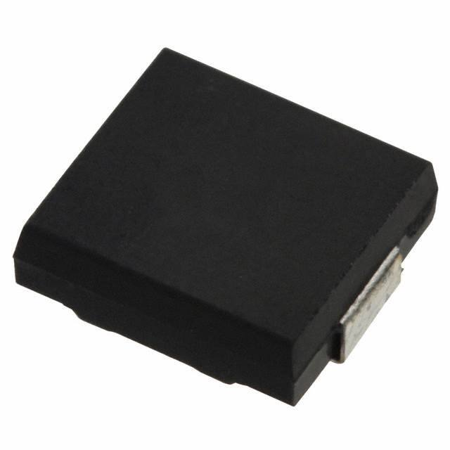
器件简介:这些电容器是树脂封装的SMD类型,适用于回流焊接,具有高可靠性,使用了圆盘电容器元件和外凸端子。

引脚分配:电容器有内端子和外端子两种风格,具体尺寸和引脚分配在文档中有详细描述。

参数特性: - 工作温度范围:SL/GP特性为-25至105°C,B/Y5P特性为-25至85°C。 - 额定电压:1至5kVDC,具有不同的介电耐压和电容公差。 - 电容值:从9pF到4700pF不等,具有不同的公差等级。 - 品质因数(Q)或耗散因子(tan):对于30pF或更小的电容,Q值大于400;对于30pF以上的电容,Q值大于1000。 - 绝缘电阻:最小为10000 MΩ,在500VDC和1分钟通电条件下。

功能详解:电容器适用于多种电路,如LCD背光逆变器的镇流电路(3至5kVDC,Char.SL/GP)和开关电源的消振电路(1至2kVDC,Char.B/Y5P)。

应用信息:电容器可用于LCD背光逆变器和开关电源的初级电路和消振电路,具体应用包括不同电压和电容值的组合。

封装信息:提供了不同的封装风格和包装方法,包括卷带包装,最小包装单位和纸箱尺寸。
ECC-T3F180JG 价格&库存

很抱歉,暂时无法提供与“ECC-T3F180JG”相匹配的价格&库存,您可以联系我们找货

免费人工找货