物料型号:文档列出了Panasonic多层陶瓷电容器(通用型)的系列型号,包括ECJ系列。
器件简介:这些电容器具有小尺寸和宽电容范围,适用于需要低损耗和高稳定性电容的调谐电路和滤波电路。
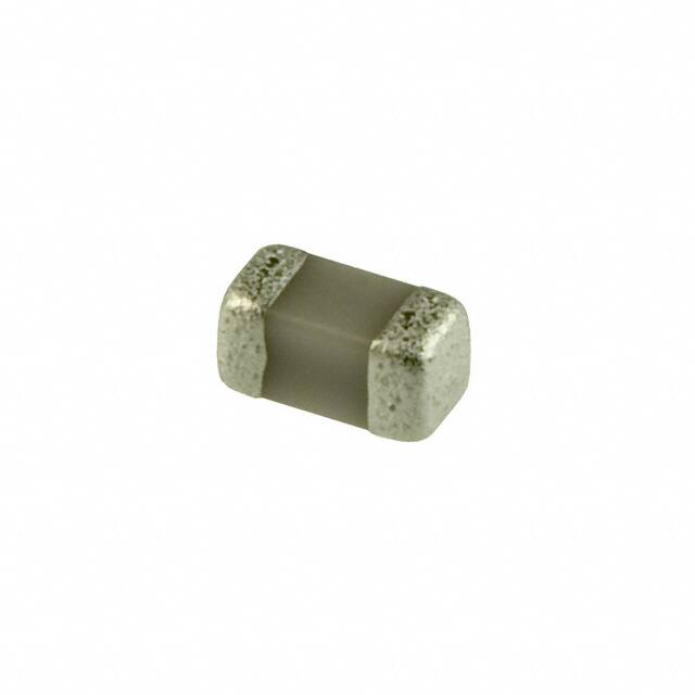
引脚分配:文档中提到了电容器的构造,包括陶瓷介质、内部电极、端电极、基底电极、中间电极和外部电极。
参数特性:
- 温度特性:分为Class 1(T.C. Type)和Class 2(Hi-K Type)。
- 额定电压:包括DC 50V、DC 25V、DC 16V、DC 10V和DC 6.3V等。
- 电容公差:根据不同的电容值有不同的公差标准。
- 温度系数:在20°C至85°C之间计算。
功能详解:电容器具有高湿度抵抗力、长寿命、优异的可焊性和抗焊热性,符合RoHS标准。
应用信息:适用于耦合和旁路应用。
封装信息:提供了不同尺寸代码的电容器尺寸,包括0201、0402、0603和0805等。
包装规格:详细列出了不同封装风格的电容器的包装方式和标准包装数量。
注意事项:在购买和/或使用前,应向工厂询问当前的技术规格。如果出现安全问题,请立即联系。