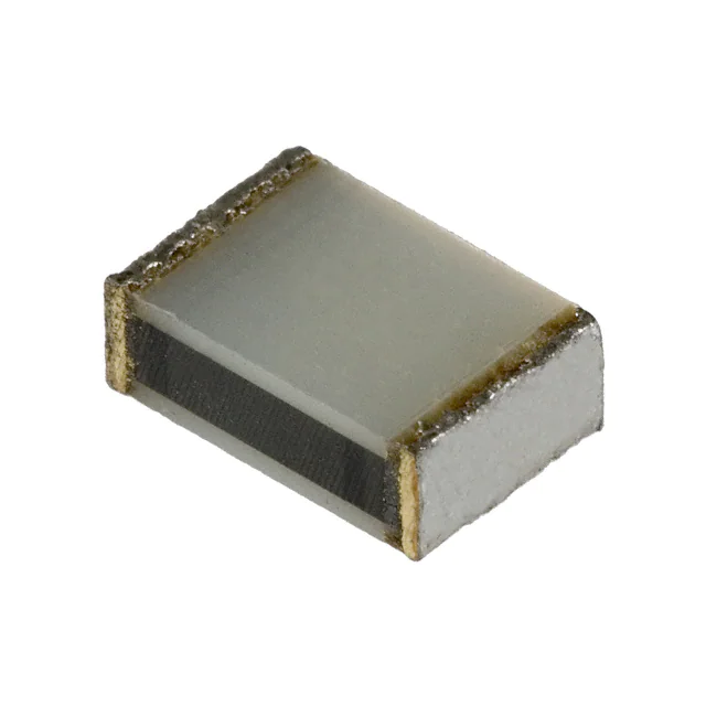
Film Chip Capacitor
Film Chip Capacitor
Type:
ECWU(C)
Stacked metallized PEN film as dielectric with simple
mold - less construction
■Features
Small in size
Applicable for reflow soldering
■Recommended Applications
Coupling
By - pass
General purpose
■Explanation of Part Numbers
1
2
3
4
E
C
W
U
Product code
Dielectric
&
construction
5
6
7
8
9
10
11
12
C
Rated voltage
Nominal capacitance
Cap. Tol. Suffix
Suffix
Tape width
1C 16VDC
1H 50VDC
1 100VDC
2 250VDC
J ±5%
K ±10%
9
V
Z
12mm
16mm
24mm
■Specifications
Category temp.range
Rated voltage
Capacitance range
Capacitance tolerance
16VDC, 50VDC: - 55 to + 105:
100VDC, 250VDC: - 40 to + 85:
16VDC, 50VDC, 100VDC, 250VDC
0.12 to 0.47 µF (E12)
16VDC
50VDC
0.056 to 0.22 µF (E12)
100VDC
0.012 to 1.0 µF (E12)
250VDC
0.001 to 1.0 µF (E12)
16VDC,50VDC
± 5%(J)
100VDC,250VDC
± 10%(K) (100VDC, C<
=0.15 µF ± 5%(J), ± 10%(K))
Withstand voltage
Between terminals
16VDC, 50VDC:Rated volt. (VDC)x175% 1 to 5s
100VDC, 250VDC:Rated volt. (VDC)x150% 60s
Dissipation factor
<
= 1.0%(20:,1kHz)
C<
= 0.33 µF
> 3000MΩ • (20:,10VDC, 60s)
16VDC:=
> 3000MΩ • (20:,50VDC, 60s)
50VDC:=
> 3000MΩ • (20:,100VDC,60s)
100VDC, 250VDC:=
C>0.33 µF
16VDC:1000MΩ • µF min. (20:,10VDC, 60s)
100VDC, 250VDC:1000MΩ • µF min. (20:,100VDC,60s)
Insulation resistance
Reflow soldering
Soldering conditions
16VDC, 50VDC:240: max. and 30 sec max. at more than 210˚C (Temp. at cap. surface)
100VDC, 250VDC:230: max. and 30 sec max.at more than 210˚C (Temp.at cap.surface)
Design and specifications are subject to change without notice. Ask factory for technical specifications before purchase and/or use.
Whenever a doubt about safety arises from this product, please contact us immediately for technical consultation.
�Film Chip Capacitor
■Dimensions in mm (not to scale)
■Construction
L
Size code
L
E1
E2
E3a
E3
D1
D2
D3
D4
D5
B
Z
X
Y
V
U
T
S
H
W
Element
(stacked)
Outer electrode
0.35± 0.2
0.35± 0.2
Tol.
W
Tol.
4.8
3.3
4.8
3.3
4.8
3.3
4.8
3.3
6.0
4.1 ± 0.3
± 0.2
4.1
6.0
4.1
6.0
4.1
6.0
6.0
4.1
6.0
5.0
7.1
5.0
7.7 ± 0.4 5.5
7.1
6.3
± 0.4
6.3
9.8
8.0
9.8
± 0.5
8.0
15.2
15.2
10.0
H Tol.
1.4
2.0
2.4
2.8
1.8 ± 0.2
2.0
2.4
2.8
3.2
❈
± 0.3
❈Refer to the column "Rating, Dimensions & Quantity".
■Taping Specification for Automatic Insertion(Mounting)
Refer to the PDF file of taping specifications.
■ Rating, Dimensions & Quantity/Reel
●Capacitance tolerance : ± 5 % (J)
Cap.
(µF)
0.056
0.068
0.082
0.1
0.12
0.15
0.18
0.22
0.27
0.33
0.39
0.47
Rated volt. 16VDC
Part No
ECWU1C124JC9
ECWU1C154JC9
ECWU1C184JC9
ECWU1C224JC9
ECWU1C274JC9
ECWU1C334JC9
ECWU1C394JC9
ECWU1C474JC9
Rated volt. 50VDC
Dimensions (mm)
L
4.8
4.8
4.8
4.8
6.0
6.0
6.0
6.0
W
H
3.3
3.3
3.3
3.3
4.1
4.1
4.1
4.1
1.4
2.0
2.0
2.4
1.8
2.0
2.4
2.8
Size
code
E1
E2
E2
E3a
D1
D2
D3
D4
Q'ty
3000
2000
Part No
ECWU1H563JC9
ECWU1H683JC9
ECWU1H823JC9
ECWU1H104JC9
ECWU1H124JC9
ECWU1H154JC9
ECWU1H184JC9
ECWU1H224JC9
Dimensions (mm)
L
4.8
4.8
4.8
4.8
6.0
6.0
6.0
6.0
W
3.3
3.3
3.3
3.3
4.1
4.1
4.1
4.1
H
2.0
2.0
2.4
2.8
1.8
2.0
2.4
2.8
Size
code
E2
E2
E3a
E3
D1
D2
D3
D4
3000
2000
■Example for Land Dimensions (mm)
Electrode
Land
C
A
B
Size code
E1,E2,E3a,E3
D1,D2,D3,D4,D5
B
Z
X
Y
V
U
T
S
Land dimensions
Reflow soldering
A
B
C
2.6
3.8
3.8
4.5
5.1
4.5
7.2
7.2
12.6
12.6
6.6
7.8
7.8
9.0
9.7
9.0
11.9
11.9
17.3
17.3
3.0
3.8
4.6
4.6
5.0
5.7
5.7
7.2
7.2
9.0
Design and specifications are subject to change without notice. Ask factory for technical specifications before purchase and/or use.
Whenever a doubt about safety arises from this product, please contact us immediately for technical consultation.
Q'ty
3000
2000
3000
2000
�Film Chip Capacitor
■ Rating, Dimensions & Quantity/Reel
●Capacitance tolerance : ± 5% (J), ± 10% (K)
Cap.
(µF)
0.001
0.0012
0.0015
0.0018
0.0022
0.0027
0.0033
0.0039
0.0047
0.0056
0.0068
0.0082
0.01
0.012
0.015
0.018
0.022
0.027
0.033
0.039
0.047
0.056
0.068
0.082
0.1
0.12
0.15
0.18
0.22
0.27
0.33
0.39
0.47
0.56
0.68
0.82
1.0
Rated volt. 100VDC
Part
No
Dimensions (mm)
L
W
H
Rated volt. 250VDC
Size
code
Q'ty
Please use 100VDC rating ECWU(X)
ECWU1123MC9
ECWU1153MC9
ECWU1183MC9
ECWU1223MC9
ECWU1273MC9
ECWU1333MC9
ECWU1393MC9
ECWU1473MC9
ECWU1563MC9
ECWU1683MC9
ECWU1823MC9
ECWU1104MC9
ECWU1124MC9
ECWU1154MC9
ECWU1184KC9
ECWU1224KC9
ECWU1274KC9
ECWU1334KC9
ECWU1394KCV
ECWU1474KCV
ECWU1564KCV
ECWU1684KCV
ECWU1824KCV
ECWU1105KCV
▲
4.8
4.8
4.8
4.8
4.8
4.8
4.8
4.8
4.8
4.8
4.8
6.0
6.0
6.0
7.1
7.1
7.1
7.1
7.7
7.7
9.8
9.8
9.8
9.8
3.3
3.3
3.3
3.3
3.3
3.3
3.3
3.3
3.3
3.3
3.3
4.1
4.1
4.1
5.0
5.0
5.0
5.0
5.5
5.5
6.3
6.3
6.3
6.3
1.4
1.4
1.4
1.4
1.4
1.4
1.4
2.0
2.0
2.4
2.8
1.8
2.4
2.8
2.0
2.4
2.9
3.5
3.4
4.0
3.0
3.6
4.3
5.1
E1
E1
E1
E1
E1
E1
E1
E2
E2
E3a
E3
D1
D3
D4
Z
Z
Z
Z
X
X
V
V
V
V
3000
2000
3000
2000
1500
1000
Part
No
ECWU2102KC9
ECWU2122KC9
ECWU2152KC9
ECWU2182KC9
ECWU2222KC9
ECWU2272KC9
ECWU2332KC9
ECWU2392KC9
ECWU2472KC9
ECWU2562KC9
ECWU2682KC9
ECWU2822KC9
ECWU2103KC9
ECWU2123KC9
ECWU2153KC9
ECWU2183KC9
ECWU2223KC9
ECWU2273KC9
ECWU2333KC9
ECWU2393KC9
ECWU2473KC9
ECWU2563KC9
ECWU2683KC9
ECWU2823KC9
ECWU2104KC9
ECWU2124KCV
ECWU2154KCV
ECWU2184KCV
ECWU2224KCV
ECWU2274KCV
ECWU2334KCV
ECWU2394KCV
ECWU2474KCV
ECWU2564KCZ
ECWU2684KCZ
ECWU2824KCZ
ECWU2105KCZ
Dimensions (mm)
L
4.8
4.8
4.8
4.8
4.8
4.8
4.8
4.8
4.8
4.8
4.8
4.8
4.8
4.8
4.8
4.8
4.8
4.8
4.8
6.0
6.0
6.0
6.0
6.0
6.0
7.1
7.1
7.1
7.1
9.8
9.8
9.8
9.8
15.2
15.2
15.2
15.2
W
3.3
3.3
3.3
3.3
3.3
3.3
3.3
3.3
3.3
3.3
3.3
3.3
3.3
3.3
3.3
3.3
3.3
3.3
3.3
4.1
4.1
4.1
4.1
5.0
5.0
6.3
6.3
6.3
6.3
6.3
6.3
8.0
8.0
8.0
8.0
10.0
10.0
H
1.4
1.4
1.4
1.4
1.4
1.4
1.4
1.4
1.4
1.4
1.4
1.4
1.4
1.4
1.4
2.0
2.0
2.4
2.8
2.0
2.4
2.8
3.2
3.2
3.8
2.8
3.5
4.1
5.1
3.9
4.8
4.4
5.3
3.7
4.4
4.2
5.1
Size
code
E1
E1
E1
E1
E1
E1
E1
E1
E1
E1
E1
E1
E1
E1
E1
E2
E2
E3a
E3
D2
D3
D4
D5
B
B
Y
Y
Y
Y
V
V
U
U
T
T
S
S
Capacitance tolerance code
❈ Please consult us for capacitance tolerance ± 5%(J).
Design and specifications are subject to change without notice. Ask factory for technical specifications before purchase and/or use.
Whenever a doubt about safety arises from this product, please contact us immediately for technical consultation.
Q'ty
3000
2000
3000
2000
1500
1000
750
�ECWU (C) Type
DC100V series (Stacked Metallized Film)
Electrical Characteristics < Typical Data >
Temperature Characteristics
Frequency Characteristics
at 1kHz
10
10
Capacitance change(%)
Capacitance change(%)
1.0uF
5
From 0.012uF to 1.0uF
0
-5
-10
0.47uF
5
0.10uF
0.047uF
0
0.012uF
-5
-10
1
-60 -40 -20 0 20 40 60 80 100120 140
10
1000
10000
Frequency (kHz)
Temperature(Dgree C)
at 1kHz
10
10
8
8
Dissipation factor(%)
Dissipation factor(%)
100
6
4
2
From 0.012uF to 1.0uF
0
1.0uF
6
0.47uF
0.10uF
4
0.047uF
2
0.012uF
0
-60 -40 -20 0 20 40 60 80 100 120 140
1
10
Temperature (Degree C)
100
1000
10000
Frequency (kHz)
at DC 100V
10000
1000
1.E+11
From 0.012uF to 0.047uF
1.E+10
1.0uF
1.E+09
1.E+08
1.E+07
Impedance(ohm)
Insuration resistance(ohm)
1.E+12
0.0
47
uF
100
0.0
0.1
1.0
u
10
F
12
uF
0u
F
0.4
7u
F
1
0.1
0.01
1.E+06
-60 -40 -20 0 20 40 60 80 100 120140
Temperature (Degree C)
0.001
1
10
100
1000
10000 100000
Frequency(kHz)
�ECWU (C) Type
DC100V series (Stacked Metallized Film)
Applicable Specifications
Permissible current
Permissible current
3
3
Effective value (A)
Effective value (A)
0.68 uF
2
0.068 uF, 0.056 uF
0.039 uF, 0.033 uF
1.0 uF
0.82 uF
0.56 uF, 0.47 uF
2
0.39 uF
0.15 uF
0.082 uF
0.027 uF, 0.022 uF
1
1
0.047 uF
0.018 uF, 0.015 uF
0.33 uF, 0.27 uF
0.012 uF
0.22 uF, 0.18 uF
0.12 uF, 0.10 uF
0
0
1
10
100
1
1000
Permissible voltage
Permissible voltage
(at sine wave)
10
0.012
0.015
0.018
0.022
0.027
0.033
0.039
0.056
0.068
0.082
(at sine wave)
100
Effective value (V)
Effective value (V)
1000
Frequency (kHz)
Frequency (kHz)
100
100
10
10
uF
uF
uF
uF
uF
uF
uF, 0.047 uF
uF
uF
uF
0.22 uF
0.27 uF
0.33 uF
0.39 uF
0.47 uF
0.56 uF
0.10 uF
0.12 uF
0.68 uF
0.82 uF
1
1
10
100
Frequency (kHz)
1000
1.0 uF
1
1
100
10
Frequency (kHz)
0.15 uF
0.18 uF
1000
* Please consult Panasonic if your condition exceeds the above spec.
*Permissible voltage graph is the case of sine waveform. When you use this product, peak voltage must not exceed DC rated voltage.
*The current value (Aop) is calculated using "nominal capacitance." In fact, it changes by the tolerance of a capacitance value, capacitance change, etc.
�ECWU (C) Type
DC100V series (Stacked Metallized Film)
Applicable Specifications
Pulse Handling Capability (dv/dt)
Pulse Handling Capability (dv/dt)
(Max 10000cycles)
(Max 10000cycles)
Rating
Voltage
DC
100V
Capacitance
Value(uF)
Code
0.012
123
0.015
Current(0-P )
dv/dt(V/us)
(A)
Rating
Voltage
Capacitance
Value(uF)
Code
3.8
0.10
104
123
4.8
0.12
124
0.018
183
5.8
0.15
154
31.5
0.022
223
7.0
0.18
184
21.6
0.027
273
8.6
0.22
224
dv/dt(V/us)
Current(0-P )
(A)
21.0
210
25.2
26.4
120
0.033
333
320
10.6
0.039
393
12.5
0.047
473
15.0
DC
100V
0.27
274
32.4
0.33
334
39.6
0.39
394
39.0
100
0.056
563
17.9
0.47
474
47.0
0.68
683
21.8
0.56
564
39.2
0.82
823
26.2
0.68
684
47.6
70
0.82
824
57.4
1.0
105
70.0
Voltage Derating by Temperature
60
DC Rated Voltage (V)
50
40
30
20
10
0
-60 -40 -20 0 20 40 60 80 100 120140
Surface Temperature of Capacitor(Degree C)
* Please consult Panasonic if your condition exceeds the above spec.
*Permissible voltage graph is the case of sine waveform. When you use this product, peak voltage must not exceed DC rated voltage.
*The current(0-P ) value is calculated using nominal capacitance.
�ECWU (C) Type
DC16V series (Stacked Metallized Film)
Electrical Characteristics < Typical Data >
Temperature Characteristics
at 1kHz
10
10
Capacitance change(%)
Capacitance change(%)
Frequency Characteristics
5
0.47uF
0
0.22uF
-5
0.22uF
5
0.47uF
0
-5
-10
-10
-60 -40 -20 0 20 40 60 80 100120 140
Temperature (Degree C)
1
10
100
1000
Frequency (kHz)
10000
10
8
8
Dissipation factor(%)
Dissipation factor(%)
at 1kHz
10
6
4
2
0.22uF
6
0.47uF
4
2
0.47uF
0.22uF
0
0
-60 -40 -20 0 20 40 60 80 100120140
1
1000
10000
10
100
1000
Frequency (kHz)
10000
10000
1.E+10
0.22uF
0.47uF
1.E+08
Impedance(ohm)
Insuration resistance(ohm)
at DC 10V
1.E+11
1.E+09
100
Frequency (kHz)
Temperature (Degree C)
1.E+12
10
1000
100
10
1
1.E+07
0.1
1.E+06
0.01
-60 -40 -20 0 20 40 60 80 100120 140
Temperature (Degree C)
0.22uF
0.47uF
1
�ECWU (C) Type
DC16V series
(Stacked Metallized Film)
Applicable Specifications
Permissible current
Permissible voltage
(at sine wave)
100
2
0.47 uF
0.39
0.33
0.27
0.22
0.18
uF
uF
uF
uF
uF
0.15 uF
0.12 uF
Effective value (V)
Effective value (A)
3
10
1
0.27 uF
0.33 uF
0.39 uF
0
10
100
Frequency (kHz)
1000
(Max 10000cycles)
Current(0-P )
(A)
0.12
124
0.15
154
0.18
184
10.8
0.22
224
13.2
0.27
274
10.8
0.33
334
0.39
394
15.6
0.47
474
18.8
16
7.2
40
9.0
13.2
DC Rated Voltage (V)
DC
16V
Code
60
1000
20
Capacitance
Value(uF)
dv/dt(V/us)
100
Frequency (kHz)
Voltage Derating by Temperature
Pulse Handling Capability (dv/dt)
Rating
Voltage
0.47 uF
1
10
0.12
0.15
0.18
0.22
12
8
4
0
-60 -40 -20 0 20 40 60 80 100 120 140
Surface Temperature of Capacitor(Degree C)
* Please consult Panasonic if your condition exceeds the above spec.
*Permissible voltage graph is the case of sine waveform. When you use this product, peak voltage must not exceed DC rated voltage.
*The current(0-P ) value is calculated using nominal capacitance.
uF
uF
uF
uF
�ECWU (C) Type
DC50V series (Stacked Metallized Film)
Electrical Characteristics < Typical Data >
Temperature Characteristics
at 1kHz
10
5
0.22uF
0.10uF
0
-5
Capacitance change(%)
10
Capacitance change(%)
Frequency Characteristics
-10
5
0.22uF
0.10uF
0
-5
-10
-60 -40 -20 0 20 40 60 80 100 120140
1
Temperature (Degree C)
10
100
1000
10000
Frequency (kHz)
10
8
8
Dissipation factor(%)
Dissipation factor(%)
at 1kHz
10
6
4
2
6
0.22uF
4
0.10uF
2
0.22uF
0.10uF
0
0
-60 -40 -20 0 20 40 60 80 100120 140
1
Temperature (Degree C)
100
1000
10000
1000
10000
Frequency (kHz)
at DC 50V
10000
1.E+11
1000
0.22uF
0.10uF
1.E+10
1.E+09
1.E+08
1.E+07
Impedance(ohm)
Insuration resistance(ohm)
1.E+12
10
100
0.10uF
10
0.22uF
1
0.1
1.E+06
0.01
-60 -40 -20 0
20 40 60 80 100 120 140
Temperature (Degree C)
1
10
100
Frequency (kHz)
�ECWU (C) Type
DC50V series
(Stacked Metallized Film)
Applicable Specifications
Permissible current
Permissible voltage
(at sine wave)
100
2
0.22 uF
0.18 uF
0.15 uF
0.12 uF
0.10 uF
0.082 uF
0.068 uF
0.056 uF
1
Effective value (V)
Effective value (A)
3
10
0.056 uF
0.068 uF
0.082 uF
0.10 uF
0.12 uF
0.15 uF
0.18 uF
0.22 uF
0
10
100
1000
1
10
100
Frequency (kHz)
Voltage Derating by Temperature
Pulse Handling Capability (dv/dt)
60
(Max 10000cycles)
DC
50V
Capacitance
Value(uF)
Code
0.056
563
0.068
683
0.082
823
15.6
0.10
104
19.0
0.12
124
15.6
0.15
154
0.18
184
23.4
0.22
224
28.6
dv/dt(V/us)
Current(0-P )
(A)
50
10.6
190
130
12.9
19.5
DC Rated Voltage (V)
Rating
Voltage
1000
Frequency (kHz)
40
30
20
10
0
-60 -40 -20 0 20 40 60 80 100 120 140
Surface Temperature of Capacitor(Degree C)
* Please consult Panasonic if your condition exceeds the above spec.
*Permissible voltage graph is the case of sine waveform. When you use this product, peak voltage must not exceed DC rated voltage.
*The current(0-P ) value is calculated using nominal capacitance.
�ECWU (C) Type
DC250V series (Stacked Metallized Film)
Electrical Characteristics < Typical Data >
Temperature Characteristics
at 1kHz
5
10
From 1000pF to 1.0uF
0
-5
Capacitance change(%)
Capacitance change(%)
10
Frequency Characteristics
-10
5
1.0uF
0.10uF
0
0.010uF
1000pF
-5
-10
1
-60 -40 -20 0 20 40 60 80 100 120140
10
Temperature (Degree C)
1000
10000
Frequency (kHz)
at 1kHz
10
Dissipation factor(%)
10
Dissipation factor(%)
100
8
6
4
2
From 1000pF to 1.0uF
8
6
1.0uF
0.10uF
4
0.010uF
2
1000pF
0
0
-60 -40 -20 0 20 40 60 80 100120 140
1
10
Temperature (Degree C)
100
1000
10000
Frequency (kHz)
at DC 100V
10000
1000
1.E+11
From 1000pF to 0.10uF
1.E+10
1.E+09
1.0uF
1.E+08
Impedance(ohm)
Insuration resistance(ohm)
1.E+12
1000pF
100
0.010uF
10
1.0uF
1.E+07
0.1
1.E+06
0.01
-60 -40 -20 0 20 40 60 80 100120 140
Temperature (Degree C)
0.10uF
1
1
10
100
1000 10000 100000
Frequency (kHz)
�ECWU (C) Type
DC250V series (Stacked Metallized Film)
Applicable Specifications
Permissible current
Permissible current
1
3
0.027 uF
0.010uF, 8200pF
0.022 uF
0.018 uF
0.5
5600pF, 4700pF
0.015 uF
0.012 uF
Effective value (A)
Effective value (A)
0.68 uF, 0.39uF
1.0 uF
0.82 uF
0.18uF, 0.27uF
2
0.47 uF
0.12 uF, 0.15uF
0.56 uF
0.33 uF
0.22 uF
6800 pF
1
3900 pF
3300 up
2700 pF
2200 pF
1800 pF
1500 pF
1200 pF
1000 pF
0.10 uF
0.056
0.047
0.033
0.039
uF
uF
uF
uF
0.068uF, 0.082uF
0
100
10
1
0
0.1
1000
1
10
Permissible voltage
1000
Permissible voltage
(at sine wave)
(at sine wave)
100
1000pF
10
10
0.033 uF
~
0.027 uF
Effective value (V)
100
~
Effective value (V)
100
Frequency (kHz)
Frequency (kHz)
1
1
1.0 uF
0.1
0.1
1
10
Frequency (kHz)
100
1000
0.1
0.1
1
10
Frequency (kHz)
100
* Please consult Panasonic if your condition exceeds the above spec.
*Permissible voltage graph is the case of sine waveform. When you use this product, peak voltage must not exceed DC rated voltage.
*The current(0-P ) value is calculated using nominal capacitance.
1000
�ECWU (C) Type
DC250V series (Stacked Metallized Film)
Applicable Specifications
Pulse Handling Capability (dv/dt)
(Max 10000cycles)
Rating
Voltage
Capacitance
Value(uF)
Code
Capacitance
Value(uF)
Code
0.0010
102
0.62
0.039
393
9.36
0.0012
122
0.74
0.047
473
11.28
0.0015
152
0.92
0.056
563
13.44
0.0018
182
1.11
0.068
683
dv/dt(V/us)
Current(0-P )
(A)
Rating
Voltage
dv/dt(V/us)
240
Current(0-P )
(A)
16.32
615
DC
250V
0.0022
222
1.35
0.082
823
19.68
0.0027
272
1.66
0.10
104
24.00
0.0033
332
2.03
0.12
124
28.80
0.0039
392
2.40
0.15
154
28.50
0.0047
472
1.69
0.18
184
0.0056
562
2.02
0.22
224
41.80
0.0068
682
2.45
0.27
274
31.05
0.0082
822
2.95
0.33
334
DC
250V
190
34.20
37.95
115
0.010
103
3.60
0.39
394
44.85
0.012
123
4.32
0.47
474
54.05
0.015
153
5.40
0.56
564
36.40
0.018
183
6.48
0.68
684
360
44.20
65
0.022
223
7.92
0.82
824
53.30
0.027
273
9.72
1.0
105
65.00
0.033
333
11.88
DC Rated Voltage (V)
300
Voltage Derating by Temperature
250
200
150
125
100
50
0
-60 -40 -20 0 20 40 60 80 100 120 140
Surface Temperature of Capacitor(Degree C)
* Please consult Panasonic if your condition exceeds the above spec.
*Permissible voltage graph is the case of sine waveform. When you use this product, peak voltage must not exceed DC rated voltage.
*The current(0-P ) value is calculated using nominal capacitance.
�


 工商网监
湘ICP备2023018690号
工商网监
湘ICP备2023018690号
