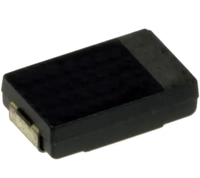
Conductive Polymer Aluminum
Electrolytic Capacitors
Surface Mount Type
CS/CT/CX series
Features
● High voltage (35 V max.)
● Low profile (Height 1.0 mm max.)
・2 to 6.3 V : On sale
● High ripple current (5600 mA rms max.)
・ 10 to 35 V : Not recommended for new design
● RoHS compliance, Halogen free
※ Click
here for Replacement (10 to 35 V)
Specifications
Series
CS
CT
Category temp. range
CX
–55 ℃ to +105 ℃
Rated voltage range
4.0 V to 35 V
Rated cap. range
10 μF to 120 μF
2.0 V to 35 V
15 μF to 180 μF
15 μF to 560 μF
Capacitance tolerance
±20 % (120 Hz / +20 ℃)
DC leakage current
I ≦ 0.1 CV(μA) [2.0 V to 6.3 V, 2 min], I ≦ 0.3 CV(μA) [10 V to 35 V, 2 min]
Dissipation factor (tan δ)
≦ 0.06 (120 Hz / + 20 ℃)
Surge voltage (V)
Rated voltage × 1.25 [2.0 V to 16 V], × 1.15 [20 V to 35 V] (15 ℃ to 35 ℃)
+105 ℃ 2000 h, rated voltage applied
Capacitance change
Within ±20 % of the initial value
Endurance
Dissipation factor (tan δ)
≦ 2 times of the initial limit
≦ 3 times of the initial limit : 2.0 V to 6.3 V
Within the initial limit : 10 V to 35 V
DC leakage current
+60 ℃, 90 % RH, 500 h, No-applied voltage
Capacitance change
of initial measurd value
Damp heat
(Steady state)
Dissipation factor (tan δ)
DC leakage current
2.0 V to 2.5 V
4.0 V, 10 V to 35 V
6.3 V
+70 %, –20 %
+60 %, –20 %
+50 %, –20 %
≦ 2 times of the initial limit
Within the initial limit : 2.0 V to 6.3 V
≦ 3 times of the initial limit : 10 V to 35 V
Dimensions (not to scale)
Capacitance (μF)
⊕
⊖
Polarity bar (Positive)
H
Marking
P
P
W1
W2
W2
L
Lot No.
R. voltage code
Unit:mm
R. voltage code
d
2.0
e
g
Unit:V
Series
L±0.2
W1±0.2 W2±0.1
H±0.1
P±0.3
6.3
D
20
CS
7.3
4.3
2.4
1.1
1.3
2.5
j
A
10
E
25
CT
7.3
4.3
2.4
1.4
1.3
4.0
C
16
V
35
CX
7.3
4.3
2.4
1.9
1.3
✽ Externals of figure are the reference.
Design and specifications are each subject to change without notice. Ask factory for the current technical specifications before purchase and/or use.
Should a safety concern arise regarding this product, please be sure to contact us immediately.
30-Jun-20
�CS/CT/CX series
Characteristics list
■ 2.0 V to 6.3 V
Series
CS
CT
Rated
voltage
(V)
Case size (mm)
Specification
Capacitance
(μF)
L
W
H
Ripple
current*1
(mA rms)
ESR*2
(mΩ max.)
Part number
Min.
Packaging
Q’ty*3
(pcs)
4.0
120
7.3
4.3
1.1
5100
15
EEFCS0G121R
3500
6.3
68
7.3
4.3
1.1
5100
15
EEFCS0J680R
3500
4.0
180
7.3
4.3
1.4
5100
15
EEFCT0G181R
3500
6.3
100
7.3
4.3
1.4
5100
15
EEFCT0J101R
3500
220
7.3
4.3
1.9
5100
15
EEFCX0D221R
3500
270
7.3
4.3
1.9
5600
12
EEFCX0D271XR
3500
7.3
4.3
1.9
5100
15
EEFCX0D331R
3500
7.3
4.3
1.9
5600
12
EEFCX0D331XR
3500
2.0
2.5
CX
330
390
7.3
4.3
1.9
5100
15
EEFCX0D391R
3500
470
7.3
4.3
1.9
5100
15
EEFCX0D471R
3500
560
7.3
4.3
1.9
5100
15
EEFCX0D561R
3500
220
7.3
4.3
1.9
5100
15
EEFCX0E221R
3500
330
7.3
4.3
1.9
5100
15
EEFCX0E331R
3500
390
7.3
4.3
1.9
5100
15
EEFCX0E391R
3500
470
7.3
4.3
1.9
5100
15
EEFCX0E471R
3500
150
7.3
4.3
1.9
5100
15
EEFCX0G151R
3500
7.3
4.3
1.9
5100
15
EEFCX0G181R
3500
7.3
4.3
1.9
5600
12
EEFCX0G181XR
3500
7.3
4.3
1.9
5100
15
EEFCX0G221R
3500
7.3
4.3
1.9
5600
12
EEFCX0G221XR
3500
7.3
4.3
1.9
5100
15
EEFCX0G271R
3500
180
4.0
220
270
6.3
330
7.3
4.3
1.9
5100
15
EEFCX0G331R
3500
100
7.3
4.3
1.9
5100
15
EEFCX0J101R
3500
120
7.3
4.3
1.9
5100
15
EEFCX0J121R
3500
7.3
4.3
1.9
5100
15
EEFCX0J151R
3500
150
7.3
4.3
1.9
5600
12
EEFCX0J151XR
3500
180
7.3
4.3
1.9
5100
15
EEFCX0J181R
3500
220
7.3
4.3
1.9
5100
15
EEFCX0J221R
3500
*1: Ripple current (100 kHz / +45 ℃)
*2: ESR (100 kHz / +20 ℃)
*3: Please contact us when 500 pcs packing is necessary.
◆ Please refer to each page in this catarog for “Reflow conditions” and “Taping specifications”.
Temperature coefficient of ripple current
Temperature
2.0 V to 6.3 V
Coefficient
T ≦ 45 ℃
1.0
45 ℃ < T ≦ 85 ℃
0.7
85 ℃ < T ≦ 105 ℃
0.25
◆ Ripple current should be controlled so that surface temperature of capacitor does not exceed the category temperature.
Design and specifications are each subject to change without notice. Ask factory for the current technical specifications before purchase and/or use.
Should a safety concern arise regarding this product, please be sure to contact us immediately.
30-Jun-20
�CS/CT/CX series
Characteristics list
■ 10 V to 35 V
Series
Rated
voltage
(V)
10
16
CS
20
25
CT
For replacement
Not Recommended for New Design
Case size (mm)
Specification
Capacitance
Min.
Packaging
Q’ty*3
(pcs)
L
W
H
Ripple
current*1
(mA rms)
ESR*2
(mΩ max.)
47
7.3
4.3
1.1
3200
40
EEFCS1A470R
3500
15
7.3
4.3
1.1
3200
40
EEFCS1C150R
3500
22
7.3
4.3
1.1
3200
40
EEFCS1C220R
3500
33
7.3
4.3
1.1
3200
40
EEFCS1C330R
3500
10
7.3
4.3
1.1
3200
40
EEFCS1D100R
3500
15
7.3
4.3
1.1
3200
40
EEFCS1D150R
3500
(μF)
Part number
22
7.3
4.3
1.1
3200
40
EEFCS1D220R
3500
10
7.3
4.3
1.1
3200
40
EEFCS1E100R
3500
15
7.3
4.3
1.1
3200
40
EEFCS1E150R
3500
35
10
7.3
4.3
1.1
3200
40
EEFCS1V100R
3500
10
68
7.3
4.3
1.4
3200
40
EEFCT1A680R
3500
16
47
7.3
4.3
1.4
3200
40
EEFCT1C470R
3500
33
7.3
4.3
1.4
3200
40
EEFCT1D330R
3500
47
7.3
4.3
1.4
3200
40
EEFCT1D470R
3500
25
22
7.3
4.3
1.4
3200
40
EEFCT1E220R
3500
35
15
7.3
4.3
1.4
3200
40
EEFCT1V150R
3500
47
7.3
4.3
1.9
3200
40
EEFCX1A470R
3500
20
10
16
CX
20
25
35
68
7.3
4.3
1.9
3200
40
EEFCX1A680R
3500
100
7.3
4.3
1.9
3200
40
EEFCX1A101R
3500
15
7.3
4.3
1.9
3200
40
EEFCX1C150R
3500
22
7.3
4.3
1.9
3200
40
EEFCX1C220R
3500
33
7.3
4.3
1.9
3200
40
EEFCX1C330R
3500
47
7.3
4.3
1.9
3200
40
EEFCX1C470R
3500
68
7.3
4.3
1.9
3200
40
EEFCX1C680R
3500
22
7.3
4.3
1.9
3200
40
EEFCX1D220R
3500
33
7.3
4.3
1.9
3200
40
EEFCX1D330R
3500
47
7.3
4.3
1.9
3200
40
EEFCX1D470R
3500
56
7.3
4.3
1.9
3200
40
EEFCX1D560R
3500
15
7.3
4.3
1.9
3200
40
EEFCX1E150R
3500
22
7.3
4.3
1.9
3200
40
EEFCX1E220R
3500
33
7.3
4.3
1.9
3200
40
EEFCX1E330R
3500
15
7.3
4.3
1.9
3200
40
EEFCX1V150R
3500
22
7.3
4.3
1.9
3200
40
EEFCX1V220R
3500
*1: Ripple current (100 kHz / +45 ℃)
*2: ESR (100 kHz / +20 ℃)
*3: Please contact us when 500 pcs packing is necessary.
◆ Please refer to each page in this catarog for “Reflow conditions” and “Taping specifications”.
Temperature coefficient of ripple current
Temperature
10 V to 35 V
Coefficient
T ≦ 45 ℃
1.0
45 ℃ < T ≦ 85 ℃
0.8
85 ℃ < T ≦ 105 ℃
0.5
◆ Ripple current should be controlled so that surface temperature of capacitor does not exceed the category temperature.
Design and specifications are each subject to change without notice. Ask factory for the current technical specifications before purchase and/or use.
Should a safety concern arise regarding this product, please be sure to contact us immediately.
30-Jun-20
�Guidelines and precautions regarding the
technical information and use of our products
described in this online catalog.
■ If you want to use our products described in this online catalog for applications requiring special
qualities or reliability, or for applications where the failure or malfunction of the products may directly
jeopardize human life or potentially cause personal injury (e.g. aircraft and aerospace equipment,
traffic and transportation equipment, combustion equipment, medical equipment, accident prevention,
anti-crime equipment, and/or safety equipment), it is necessary to verify whether the specifications of
our products fit to such applications. Please ensure that you will ask and check with our inquiry desk
as to whether the specifications of our products fit to such applications use before you use our products.
■ The quality and performance of our products as described in this online catalog only apply to our
products when used in isolation. Therefore, please ensure you evaluate and verify our products under
the specific circumstances in which our products are assembled in your own products and in which our
products will actually be used.
■ Please ensure the safety by means of protection circuit, redundant circuit etc. in your system design
in order to prevent the occurrence of life crisis and other serious damages due to the failure of our
products.
■ The products and product specifications described in this online catalog are subject to change for
improvement without prior notice. Therefore, please be sure to request and confirm the latest product
specifications which explain the specifications of our products in detail, before you finalize the design
of your applications, purchase, or use our products.
■ The technical information in this online catalog provides examples of our products' typical operations
and application circuits. We do not guarantee the non-infringement of third party's intellectual property
rights and we do not grant any license, right, or interest in our intellectual property.
■ If any of our products, product specifications and/or technical information in this online catalog is to
be exported or provided to non-residents, the laws and regulations of the exporting country,
especially with regard to security and export control, shall be observed.
■ The switchover date for compliance with the RoHS Directive/REACH Regulations varies depending
on the part number or series of our products.
■ When you use the inventory of our products for which it is unclear whether those products are
compliant with the RoHS Directive/REACH Regulation, please select "Sales Inquiry" in the website
inquiry form and contact us.
Please note that we do not owe any liability and responsibility if our products are used beyond
the description of this catalog or without complying with precautions in this catalog.
25-Nov-22
�Notices / Items to be observed
Notices
■ Applicable laws and regulations
・This product complies with the RoHS Directive (Restriction of the use of certain hazardous substances in electrical and
electronic equipment (DIRECTIVE 2011/65/EU and(EU)2015/863)).
・ No Ozone Depleting Chemicals(ODC's), controlled under the Montreal Protocol Agreement, are used in producing
this product. We do not use PBBs or PBDEs as brominated flame retardants.
・ Export procedure which followed export related regulations, such as foreign exchange and a foreign trade method,
on the occasion of export of this product.
・ These products are not dangerous goods on the transportation as identified by UN(United Nations) numbers or UN
classification.
■ Limited applications
・ This capacitor is designed to be used for electronics circuits such as audio/visual equipment, home appliances,
computers and other office equipment, optical equipment, measuring equipment.
・ An advanced specification must be signed individually for high-reliability use that might threaten human life or
property due to a malfunction of the capacitor.
■ Intellectual property rights and licenses
・ The technical information in this specification provides examples of our products' typical operations and application
circuits. We do not guarantee the non-infringement of third party's intellectual property rights and we do not grant
any license, right, or interest in our intellectual property.
Items to be observed
■ For specification
・ This specification guarantees the quality and performance of the product as individual components.
The durability differs depending on the environment and the conditions of usage.
Before use, check and evaluate their compatibility with actual conditions when installed in the products.
When safety requirements cannot be satisfied in your technical examination, inform us immediately.
・ Do not use the products beyond the specifications described in this document.
■ Upon application to products where safety is regarded as important
Install the following systems for a fail-safe design to ensure safety if these products are to be used in equipment where
a defect in these products may cause the loss of human life or other signification damage, such as damage to vehicles
(automobile, train, vessel), traffic lights, medical equipment, aerospace equipment, electric heating appliances,
combustion/ gas equipment, rotating rotating equipment, and disaster/crime prevention equipment.
(1) The system is equipped with a protection circuit and protection device.
(2) The system is equipped with a redundant circuit or other system to prevent an unsafe status in the event
of a single fault.
■ Conditions of use
・ Before using the products, carefully check the effects on their quality and performance, and determined whether or not they
can be used. These products are designed and manufactured for general-purpose and standard use in general electronic
equipment. These products are not intended for use in the following special conditions.
(1) In liquid, such as Water, Oil, Chemicals, or Organic solvent.
(2) In direct sunlight, outdoors, or in dust.
(3) In vapor, such as dew condensation water of resistive element, or water leakage, salty air, or air with a high
concentration corrosive gas, such as Cl2, H2S, NH3, SO2, or NOx.
(4) In an environment where strong static electricity or electromagnetic waves exist.
(5) Mounting or placing heat-generating components or inflammables, such as vinyl-coated wires, near these products.
(6) Sealing or coating of these products or a printed circuit board on which these products are mounted, with resin and
other material.
(7) Using resolvent, water or water-soluble cleaner for flux cleaning agent after soldering. (In particular, when using water or
a water-soluble cleaning agent, be careful not to leave water residues)
(8) Using in the atmosphere where strays acid or alkaline.
(9) Using in the atmosphere where there are excessive vibration and shock.
(10) Using in the atmosphere where there are low pressure or decompression.
・ Please arrange circuit design for preventing impulse or transitional voltage.
Do not apply voltage, which exceeds the full rated voltage when the capacitors receive impulse voltage, instantaneous high
voltage, high pulse voltage etc.
・ Our products there is a product are using an electrolyte solution. Therefore, misuse can result in rapid deterioration of
characteristics and functions of each product. Electrolyte leakage damages printed circuit and affects performance,
characteristics, and functions of customer system.
16-Apr-21
�Conductive Polymer Aluminum Electrolytic Capacitors
Application Guidelines(SP-Cap)
1. Circuit design
1.1 Prohibited circuits for use
Do not use the SP-Cap with the following circuit.
(1) High-impedance voltage retention circuits
(2) Coupling circuits
(3) Time-constant circuit
(4) Circuit which are greatly affected by leakage current
(5) 2 or more SP-Cap connected serially
1.2 Voltage and polarity
The application of over- voltage and reverse voltage described below can cause increases in leakage current
and short circuits. Applied voltage, refers to the voltage value including the peak value of the transitional
Instantaneous voltage and the peak value of ripple voltage, not just steady line voltage.
Design your circuit so than the peak voltage does not exceed the stipulated voltage.
【Over-Voltage】
Do not apply over-voltage in excess of the rated voltage. Do not apply voltage, which exceeds the full
rated voltage when the SP-Cap receive impulse voltage, instantaneous high voltage, high pulse voltage
etc.
【Reverse-Voltage】
Do not apply reverse-voltage
1.3 Ripple current
Use the SP-Cap within the stipulated permitted ripple current.
When excessive ripple current is applied to the SP-Cap, if causes increases in leakage current and short
circuits due to self-heating.
Even when using the SP-Cap under the permissible ripple current, reverse voltage may occur if the DC bias
voltage is low.
1.4 Leakage current
There is a risk of leakage current characteristics increasing even if the following use environments are within
the stipulated range. However, even if the leakage current increases, the SP-Cap self-repairing function will
reduce the leakage current in most cases when a voltage is applied.
(1) After reflow
(2) Shelf conditions such as high temperature with no load, high temperature high humidity with no load and
sudden temperature changes.
1.5 Temperature
(1) Use at or under the rated (guaranteed) temperature.
Operation at temperatures exceeding specifications causes large changes in the SP-Cap electrical
properties, and deterioration than can potentially lead to failure.
When calculating the operating temperature of the SP-Cap, be sure to include not only the ambient
temperature and internal temperature of the unit, but also radiation from heat generating elements inside
the unit (power transistors, resistors, etc.), and self-heating due to ripple current.
(2) Specified ESR is a value at the time of shipping from factory. ESR may change upon use conditions.
1.6 Failure rate
The majority of failure modes are short circuits or increases in leakage current.
The main factors of failure are mechanical stress, heat stress and electric stress due to re-flow and heat from
the use temperature environment.
Even within the stipulated limits, it is possible to lower the failure rate by reducing use conditions such as
temperature and voltage. Please be sure to have ample margin in your design.
【Expected Failure Rate】
(a) Date based on our reliability tests: 8.2 Fit or less (Based on applied rated voltage at 105 °C)
(b) Market failure rate: 0.13 Fit or less (Based on c=0, Reliability standard : 60 %)
1.7 Mounting area consideration
Isolate the surface of PCB under the mounted SP-Cap.
16-Apr-21
�Conductive Polymer Aluminum Electrolytic Capacitors
2. Mounting
2.1 When mounting
(1) Check the SP-Cap ratings (capacitance and voltage) before mounting.
(2) Check the SP-Cap polarity before mounting.
(3) Check the land size for the SP-Cap before mounting.
(4) When using a mounter, if the pressure for mounting is too high, then the current leak may increase,
shortcircuiting may occur, or the SP-Cap may break down or come off.
2.2 Soldering
(1) Reflow soldering
Be performed by one of following methods.
(a) Ambient heat conduction reflow (IR / Hot-air)
Please refer to the page of “Mounting Specifications”.
(b) Vapor phase reflow (but only allowable for CX, CT, SX, ST, GX, LX, LT and HX series).
Please contact Panasonic for details of allowable vapor phase reflow condition.
(2) Wave soldering and dip soldering
Please remind SP-Cap is NOT compatible.
(3) Hand soldering
Excessive force stress to the SP-Cap should be avoided
Conditions
Tip temperature of soldering iron
:350 °C max.
Exposure time
:10 s max.
※ Once removed from the printed circuit board for any reason, please do not use the SP-Cap again.
2.3 Land size
Refer to the land size of “Mounting specifications” for appropriate design dimensions.
Circuit board design requires examination of the most suitable dimensions taking conditions such as circuit
board, parts and reflow into consideration.
2.4 Mechanical stress
Do not apply excessive force to the SP-Cap this can damage the electrodes and badly affect the SP-Cap
mount ability. It can also cause the increase of leakage current, separation of the lead wire and element,
and damage to the SP-Cap body, all of which can badly affect the electrical performance of the SP-Cap.
2.5 Circuit board cleaning
SP-Cap should be cleaned after soldering in accordance with the following conditions.
Temperature
:Less than 60 °C
Time
:Within 5min
Be sure to sufficiently wash and dry (20 min at 100 °C) the board afterward.
【Recommended Cleaning Solvents】
Pine Alpha ST-100S, Clean-thru 750H / 750L / 710M, Aqua Cleaner 210SEP, Sunelec B-12
DK Beclear CW-5790, Techno Cleaner 219, Cold Cleaner P3-375, Telpene Cleaner EC-7R
Technocare FRW-17 / FRW-1 / FRV-1, AXREL 32, IPA (Isopropyl alcohol)
(1) Consult our factory when performing processes with cleaning solvents other than those listed above
or deionized water.
(2) The use of ozone depleting cleaning agents are not recommended in the interest of protecting the
environment.
(3) In the case of using ultrasonic cleaning, the terminals may be broken. Therefore, please test before
using in mass production.
3. Usage environment of equipment
Avoid using equipment to which SP-Cap are fi ted in the following environments.
(1) In liquid, such as Water, Oil, Chemicals, or Organic solvent.
(2) In direct sunlight, outdoors, or in dust.
(3) In vapor, such as dew condensation water of resistive element, or water leakage, salty air, or air with
a high concentration corrosive gas, such as Cl2, H2S, NH3, SO2, or NO2.
(4) In an environment where strong static electricity or electromagnetic waves exist.
(5) Mounting or placing heat-generating components or inflammables, such as vinyl-coated wires, near
these SP-Cap.
(6) Sealing or coating of these SP-Cap or a printed circuit board on which these SP-Cap are mounted,
with resin and other material.
(7) Acid or alkaline environments.
(8) Environment subject to excessive vibration and shock.
16-Apr-21
�Conductive Polymer Aluminum Electrolytic Capacitors
4. Storage
SP-Cap should be stored in a moisture proof environment. Storage conditions before and after opening the
moisture proof packaging as follows.
(If these conditions are exceeded, the package may absorb moisture and there is a risk of damage to the
exterior due to heat stress during mounting.)
【Environment of Storage】
Temperature
:5 ℃ to 30 ℃
Humidity
:Less than 70 %
Maximum storage term before opening the package
:2 years after manufactured
Maximum storage condition after opening the package
:7 days after opening
SP-Cap should be all used within the storage term after opening the package.
5. Transportation
Take sufficient care during handling because excessive vibration, or shock can cause the reliability of the
SP-Cap to decrease.
6. Emergency procedures
If the SP-Cap is overheated, the resin case may emit smoke. If this occurs, immediately switch off the
unit’s main power supply to stop operation. Keep your face and hands away from the SP-Cap the
temperature may be high enough to cause the SP-Cap to ignite and burn.
7. Discarding
Since SP-Cap are composed of various metals and resins, treat them as industrial waste when arranging
for their disposal.
The precautions in using aluminum electrolytic capacitors follow the "Safety application
guide for the use in fixed aluminum electrolytic capacitors for electronic equipment",
RCR-2367D issued by JEITA in October 2017.
Please refer to the above application guide for details.
✽ Intellectual property right
We, Panasonic Group are providing the product and service that customers can use without anxiety,
working positively on the protection of our products under intellectual property rights.
Representative patents relating to SP-Cap are as follows :
US Patent No. 7136276, No. 7787234
16-Apr-21
�


 工商网监
湘ICP备2023018690号
工商网监
湘ICP备2023018690号


