SAW Resonators
SAW Resonators
n n n n MS03 n
n n n n MS12 n
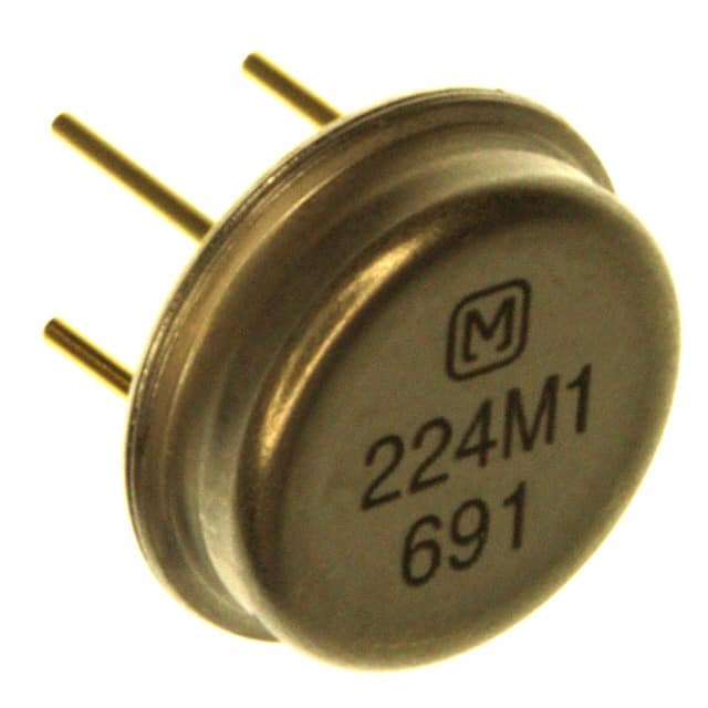
Saw Resonator, UHF, Frequency 200–700 MHz
EFOH
EFOH
EFO-H
SAW Resonators are capable of fundamental wave oscillation,
and are particularly suited for simplification, size reduction,
and stabilization of circuit, compared with conventional LC
oscillation and quartz crystal oscillation.
■ Features
• Capable of fundamental oscillation
■ Recommended Applications
• Capable of fundamental oscillation
• Superior temperature characteristics
• Superior temperature characteristics
• Suited for simplification, size reduction, and
stabilization of the circuit
• Suited for simplification, size reduction, and
stabilization of the circuit
• Wide frequency range: 200 to 700 MHz (available for
requested frequency)
• Wide frequency range: 200 to 700 MHz (available for
requested frequency)
■ Explanation of Part Numbers
E
F
O
H
Product Code
EFO Resonators
Type
H
SAW
M
Nominal Frequency
295M
310M
312M
318M
295 MHz
310 MHz
312 MHz
318 MHz
S
Material/Package
S Quartz crystal
Round can type
Type
0
1
Design No.
2 port
1 port
Frequency Tolerance
Nil.
±250 kHz
A to Z Special
Examples
■ Ratings and Characteristics
2 Port Type—Operating temperature range: –20 to 80°C / Phase shift: 180°
Part No.
EFOH200MS03
EFOH214MS03
EFOH220MS03
EFOH2243S03
EFOH225MS03
EFOH235MS03
EFOH245MS03
EFOH250MS03
EFOH270MS03
EFOH287MS03
EFOH290MS03
EFOH295MS03
EFOH300MS03
Center Frequency
200.000 ±0.250
214.000 ±0.250
220.000 ±0.250
224.300 ±0.250
224.700 ±0.250
235.400 ±0.250
245.000 ±0.250
250.000 ±0.250
270.000 ±0.250
287.995 ±0.250
290.000 ±0.250
295.000 ±0.250
300.000 ±0.250
Insertion Loss (dB)
15 max.
Loaded Q
700 min.
Capacitance (pF)
1.3 ±0.3
Temperature
Characteristics
Max. frequency drift:
–150 to 50 ppm/ °C
(–20 to 80°C)
(continued on following page)
Design and specifications are subject to change without notice. Ask factory for technical specifications before purchase and/or use.
Whenever a doubt about safety issues arises from this product, please inform us immediately for technical consultation.
�SAW Resonators
■ Ratings and Characteristics (cont’d)
2 Port Type (cont’d)—Operating temperature range: –20 to 80°C / Phase shift: 180°
Part No.
EFOH301MS03
EFOH304MS03
EFOH3043S03
EFOH3046S03
EFOH306MS03
EFOH307MS03
EFOH310MS03
EFOH311MS03
EFOH312MS03
EFOH314MS03
EFOH3145S03
EFOH3148S03
EFOH315MS03
EFOH318MS03
EFOH3195S03
EFOH330MS03
EFOH350MS03
EFOH370MS03
EFOH379MS03
EFOH384MS03
EFOH390MS03
EFOH395MS03
EFOH400MS03
EFOH402MS03
EFOH403MS03
EFOH407MS03
EFOH410MS03
EFOH411MS03
EFOH417MS03
EFOH418MS03
EFOH419MS03
EFOH423MS03
EFOH425MS03
EFOH430MS03
EFOH4332S03
EFOH4337S03
EFOH338S03
EFOH434MS03
EFOH450MS03
EFOH453MS03
EFOH458MS03
EFOH470MS03
EFOH490MS03
EFOH510MS03
EFOH530MS03
EFOH550MS03
EFOH570MS03
EFOH590MS03
EFOH610MS03
EFOH630MS03
EFOH650MS03
EFOH674MS03
Center Frequency
300.700 ±0.250
303.875 ±0.250
304.300 ±0.250
304.600 ±0.250
306.000 ±0.250
307.300 ±0.250
310.000 ±0.250
310.700 ±0.250
312.000 ±0.250
314.200 ±0.250
314.575 ±0.250
314.870 ±0.250
315.000 ±0.250
318.000 ±0.250
319.500 ±0.250
330.000 ±0.250
350.000 ±0.250
370.000 ±0.250
379.000 ±0.250
384.000 ±0.250
390.000 ±0.250
395.000 ±0.250
400.000 ±0.250
402.080 ±0.250
403.550 ±0.250
407.350 ±0.250
410.000 ±0.250
410.700 ±0.250
417.000 ±0.250
418.000 ±0.250
419.000 ±0.250
423.220 ±0.250
425.000 ±0.250
430.000 ±0.250
433.200 ±0.250
433.750 ±0.250
433.890 ±0.250
433.920 ±0.250
450.000 ±0.250
450.000 ±0.250
458.850 ±0.250
470.000 ±0.250
490.000 ±0.250
510.000 ±0.250
530.000 ±0.250
550.000 ±0.250
570.000 ±0.250
590.000 ±0.250
610.000 ±0.250
630.000 ±0.250
650.000 ±0.250
674.000 ±0.250
Insertion Loss (dB)
Loaded Q
Capacitance (pF)
Temperature
Characteristics
700 min.
15 max.
Max. frequency drift:
–150 to 50 ppm/°C
(–20 to 80°C)
1.3 ± 0.3
500 min.
Design and specifications are subject to change without notice. Ask factory for technical specifications before purchase and/or use.
Whenever a doubt about safety issues arises from this product, please inform us immediately for technical consultation.
�SAW Resonators
■ Ratings and Characteristics (cont’d)
1 Port Type (cont’d)—Operating temperature range: –20 to 80°C
Part No.
EFOH100MS11
EFOH160MS11
EFOH168MS11
EFOH176MS11
EFOH192MS11
EFOH200MS12
EFOH224MS12
EFOH225MS12
EFOH235MS12
EFOH240MS12
EFOH246MS12
EFOH264MS11
EFOH266MS11
EFOH280MS16
EFOH290MS12
EFOH293MS12
EFOH300MS11
EFOH300MS12
EFOH301MS12
EFOH303MS11
EFOH304MS11
EFOH304MS12
EFOH3043S16
EFOH308MS12
EFOH310MS12
EFOH312MS12
EFOH313MS12
EFOH314MS12
EFOH315MS16
EFOH316MS16
EFOH318MS12
EFOH320MS11
EFOH325MS12
EFOH328MS11
EFOH330MS12
EFOH333MS11
EFOH334MS12
EFOH345MS16
EFOH355MS12
EFOH360MS12
EFOH364MS12
Resonant Frequency
100.000 ±0.250
160.000 ±0.250
168.000 ±0.250
176.000 ±0.250
192.250 ±0.250
200.000 ±0.250
224.500 ±0.250
224.700 ±0.250
235.200 ±0.250
240.000 ±0.250
246.150 ±0.250
264.000 ±0.250
266.000 ±0.250
280.000 ±0.250
290.000 ±0.250
293.650 ±0.250
300.000 ±0.250
300.00 ±0.250
300.700 ±0.250
303.000 ±0.250
303.875 ±0.250
303.875 ±0.250
304.300 ±0.250
308.000 ±0.250
310.000 ±0.250
312.000 ±0.250
313.500 ±0.250
314.200 ±0.250
315.000 ±0.250
316.025 ±0.250
318.000 ±0.250
320.000 ±0.250
325.700 ±0.250
328.000 ±0.250
330.000 ±0.250
333.000 ±0.250
334.000 ±0.250
345.000 ±0.250
355.700 ±0.250
360.000 ±0.250
364.000 ±0.250
Resonant Resistance
90 Ω max.
50 Ω max.
50 Ω max.
50 Ω max.
50 Ω max.
30 Ω max.
30 Ω max.
30 Ω max.
30 Ω max.
30 Ω max.
30 Ω max.
40 Ω max.
40 Ω max.
30 Ω max.
30 Ω max.
30 Ω max.
40 Ω max.
30 Ω max.
30 Ω max.
40 Ω max.
40 Ω max.
40 Ω max.
30 Ω max.
30 Ω max.
30 Ω max.
30 Ω max.
30 Ω max.
30 Ω max.
30 Ω max.
30 Ω max.
30 Ω max.
40 Ω max.
30 Ω max.
40 Ω max.
30 Ω max.
40 Ω max.
30 Ω max.
30 Ω max.
30 Ω max.
30 Ω max.
30 Ω max.
Capacitance (pF)
2.5 ±0.5
2.5 ±0.5
2.5 ±0.5
2.5 ±0.5
2.5 ±0.5
3.0 ±0.5
3.0 ±0.5
2.5 ±0.5
2.5 ±0.5
3.0 ±0.5
2.5 ±0.5
1.4 ±0.5
1.4 ±0.5
2.0 ±0.5
2.0 ±0.5
2.0 ±0.5
1.4 ±0.5
2.0 ±0.5
2.0 ±0.5
1.4 ±0.5
1.4 ±0.5
1.4 ±0.5
2.0 ±0.5
2.0 ±0.5
2.0 ±0.5
2.0 ±0.5
2.0 ±0.5
2.0 ±0.5
2.0 ±0.5
2.0 ±0.5
2.0 ±0.5
1.4 ±0.5
2.0 ±0.5
1.4 ±0.5
2.0 ±0.5
1.4 ±0.5
2.0 ±0.5
2.0 ±0.5
2.0 ±0.5
2.0 ±0.5
2.0 ±0.5
Temperature
Characteristics
Max. frequency drift:
–150 to 50 ppm/°C
(–20 to 80°C)
Note: Also available are types other than above standard products in the frequency range of 200 to 700 MHz. Other frequencies are also available. Please consult Panasonic.
(continued on following page)
Design and specifications are subject to change without notice. Ask factory for technical specifications before purchase and/or use.
Whenever a doubt about safety issues arises from this product, please inform us immediately for technical consultation.
�SAW Resonators
■ Ratings and Characteristics (cont’d)
1 Port Type (cont’d)—Operating temperature range: –20 to 80°C
Part No.
EFOH380MS11
EFOH389MS12
EFOH396MS11
EFOH400MS11
EFOH404MS12
EFOH407MS12
EFOH417MS12
EFOH418MS16
EFOH419MS12
EFOH422MS12
EFOH423MS16
EFOH4332S12
EFOH434MS16
EFOH458MS11
EFOH460MS12
EFOH479MS16
EFOH490MS16
Resonant Frequency
380.000 ±0.250
389.000 ±0.250
396.000 ±0.250
400.000 ±0.250
404.000 ±0.250
407.300 ±0.250
417.000 ±0.250
418.000 ±0.250
419.000 ±0.250
422.500 ±0.250
423.220 ±0.250
433.200 ±0.250
433.920 ±0.250
458.650 ±0.250
460.000 ±0.250
460.000 ±0.250
460.000 ±0.250
Resonant Resistance
40 Ω max.
30 Ω max.
40 Ω max.
40 Ω max.
30 Ω max.
30 Ω max.
30 Ω max.
30 Ω max.
30 Ω max.
30 Ω max.
30 Ω max.
30 Ω max.
30 Ω max.
40 Ω max.
30 Ω max.
30 Ω max.
30 Ω max.
Temperature
Characteristics
Capacitance (pF)
1.4 ±0.5
2.0 ±0.5
1.4 ±0.5
1.4 ±0.5
2.0 ±0.5
2.0 ±0.5
2.0 ±0.5
2.0 ±0.5
2.0 ±0.5
2.0 ±0.5
2.0 ±0.5
2.0 ±0.5
2.0 ±0.5
1.4 ±0.5
2.0 ±0.5
2.0 ±0.5
2.0 ±0.5
Max. frequency drift:
–150 to 50 ppm/°C
(–20 to 80°C)
Note: Also available are types other than above standard products in the frequency range of 200 to 700 MHz. Other frequencies are also available. Please consult Panasonic.
■ Dimensions in mm (not to scale)
■ Test Circuits Diagram
SAW Resonator
φ 9.1
2
2.5 min. 3.0 max.
1
3–φ0.45
3
5.08 ± 0.20
2
1
3
Terminal
(1) Input or Output
(2) Output or Input
(3) Ground
Standard measuring voltage: –6 dBm between pins 1 and 2 (0.112 Vrms)
S: Standard signal generator (Output impedance 50 Ω)
C: Frequency counter
DET: Detector (Input impedance 50 Ω)
Design and specifications are subject to change without notice. Ask factory for technical specifications before purchase and/or use.
Whenever a doubt about safety issues arises from this product, please inform us immediately for technical consultation.
�SAW Resonators
■ Typical Characteristics
EFOH315MS03
0
0
10
10
Attenuation (dB)
Attenuation (dB)
EFOH315MS12
20
30
40
20
30
40
314.5
315.0
Frequency (MHz)
315.5
314.5
315.0
Frequency (MHz)
■ Application Example
25C3356
8.2 kΩ
100 Ω
1 pF
L1
C1
4700 pF
SAW Resonator
22k X 8
1
006P
100 µF
0.1 µF
11 12 13
1 2 3 4 5 6 7 9
9V
MC145026
16
14 15
1.2 kΩ
150 kΩ
330 kΩ
470 pF
L3
4.7 kΩ
5.6 kΩ
2.2 kΩ
70 pF
TC1
L2 2200 pF
1Ω
Oscillation Circuit (Transmitting circuit for remote control)
8
DIP SWITCH
Spectrum of Frequency (Output Wave Form)
Modulated Wave Form
0
0
Oscillation Frequency: 239.92631MHz
–20
Output Level (dBm)
Output Level (dBm)
Center Frequency: 239.966 MHz
–40
–20
–40
–60
–60
–80
–80
Frequency (50 kHz/div.)
Time (5 ms/div.)
Design and specifications are subject to change without notice. Ask factory for technical specifications before purchase and/or use.
Whenever a doubt about safety issues arises from this product, please inform us immediately for technical consultation.
315.5
�SAW Resonators
■ Application Example (cont’d)
Local Oscillation Circuit
(Local Oscillation Circuit for Receiver)
Local Oscillation Output
2.2kΩ
2pF
2SC2223
1 pF
1 kΩ
1000 pF
470 pF
6 pF
470 pF
1 pF
2.2 kΩ
330 kΩ
100 Ω
2SC3356
4.7 kΩ
8.2 kΩ
47Ω
Vcc
Saw Resonator
■ Application Notes
1. Electrostatic Discharge. The SAW filters and SAW
resonators, which have extremely narrow spacings
between their interdigitated electrodes, shall be free from
high voltage spikes such as “Electrostatic Discharges,” to
prevent failures and damages of the devices. The
following countermeasures are recommended: (a)
ground human body via earth band; (b) set electricity
rejecting sheet to working table.
6. Abnormal Mechanical Stresses. Abnormal/excess
mechanical stress such as pulling or bending forces shall
not be applied to the SAW filters and resonators for
preventing failures and damages of the devices.
2. Grounding of the Equipment. Direct
impression/application of line voltage to the SAW filters
and resonators shall cause short circuits between their
interdigitated electrodes.
8. Soldering to the Metallic Cases. The metallic cases of
the SAW filters and resonators shall not be soldered for
the purpose of grounding. Soldering to the metallic cases
may cause deterioration or damage in mechanical and
electrical characteristics.
3. Operating Temperature Range. The SAW filters and
resonators shall not be operated beyond the specified
“Operating Temperature Range” in the catalog and the
specifications.
4. R.F. Input Power. The SAW filters and resonators shall
not be operated beyond the specified “Maximum R.F.
Input Power Ratings” listed in specifications.
5. Application of DC Voltage. Application of DC voltage to
the SAW filters and resonators shall cause failures and
deterioration of the devices. DC voltage shall be cut by a
capacitor.
7. Ultrasonic Cleaning. Ultrasonic cleaning may cause
deterioration and damage in mechanical and electrical
characteristics of the devices, and shall not be applied to
the SAW filters and resonators.
9. Operating and Storage Conditions. The SAW filters and
resonators shall not be operated and stored under the
following environmental conditions: (a) exposed directly
to water or salt water; (b) exposed directly to sunlight; (c)
under conditions of humidity and dust; (d) under
conditions of corrosive atmosphere such as hydrogen
sulfide, sulfurous acid, chlorine, or ammonia.
Design and specifications are subject to change without notice. Ask factory for technical specifications before purchase and/or use.
Whenever a doubt about safety issues arises from this product, please inform us immediately for technical consultation.
�Ceramic Resonators (Chip Type)
■ Typical Characteristics
■ Recommended Land Dimensions
Type P
(EFOS4004B5)
Ceramic Resonator, Chip Type
Land
c
Solder resist
c
Oscillation Frequency Drift (%)
0.4
0.2
b
b
2a
0
b
2a
Type S
–0.2
Ceramic Resonator, Chip Type
–20
0
40
20
60
Solder resist
Land
80
c
–0.4
b
Solder resist
c
Temperature (°C)
b
b
a
■ Packaging Specifications
b
a
b
Solder resist
b
a
b
a
■ Application Notes
Soldering Conditions
Standard Packing Quantity
Style
Embossed Taping
Bulk
Quantity
2,500 pcs./reel
500 pcs./bag
Reflow soldering shall be done at 220°C for less than
10 seconds, and peak temperature of 240°C. Flow
soldering method and dip soldering method shall not
be applied.
■ Dimensions for Reel in mm (not to scale)
T
Dimensions (mm)
φA
330
φB
50 min.
C
13.0 ± 0.5
D
21.0 ± 0.8
E
2.0 ± 0.2
W
16.4
T
22.4 max.
t
3 max.
r
1.0
E
φB
φC
D
r
φA
W
t
+2.0
0
Design and specifications are subject to change without notice. Ask factory for technical specifications before purchase and/or use.
Whenever a doubt about safety issues arises from this product, please inform us immediately for technical consultation.
�
很抱歉,暂时无法提供与“EFO-H224MS12”相匹配的价格&库存,您可以联系我们找货
免费人工找货