Power Inductors
Choke Coils
Series : Pin terminal
Type : 09D, 11D, 12D, 16B, 18B,
Type 09D
Type 11D
Type 12D
Type 16B
Type 18B
Type 10E–L
10E, 12E, 15E, 18E
Pin terminal inductors featuring small size
and high performance
Features
● High - µ and High Bm cores
● Wide inductor range
● Magnetic shield type (E Type)
● RoHS compliant
Recommended Applications
● Appliance,
Office automation equipment,
Amusement machine, Power circuit for electric
device
Type 12E–L
Type 15E–L
Type 18E–L
Explanation of Part Numbers
1
2
3
4
5
6
7
8
9
E
L
C
0
9
D
2
R
2
Product code
Style
09
Core
D
Terminal
11
Core size
12
Terminal board
or
15
Construction
10
✽
Inductance
Core
Case
Terminal
B
Core
Terminal board
Terminal
E
Core (Magnetic Shielded)
Terminal board
Terminal
11
Packaging Design No.
✽
Taping
D
Other
Omission
E, F etc.
Case size
16
18
Core
P
Direct terminal by wire
Available I-L Characteristics
L (µH)
10000
L (µH)
10000
5000
5000
10E
15E
12E
18E
1000
1000
09D
500
16B
18B
500
100
100
50
50
10
10
5
5
1
1
10
50
100
500
1000
5000 10000
10
50
100
500
1000
IDC(mA)
Design and specifications are each subject to change without notice. Ask factory for the current technical specifications before purchase and/or use.
Should a safety concern arise regarding this product, please be sure to contact us immediately.
02
5000 10000
IDC(mA)
Oct. 2014
�Power Inductors
Performance Characteristics by Series
Type
09D
Regular
11D
✽
✽
12D
Construction
Extermal
Dimensions
D×H (mm)
09.5×8.9
(with case)
011.5×13.9
(with case)
Inductance
0.1
1.0
10
100
18B
10E–L
2.2
10000
0.16 to 5.3
012.5×16.5
0.27 to 1.9
18E–L
10000
016.0×23.0
0.26 to 8.5
3.3
10000
3.3
10000
020.0×27.0
0.36 to 8.5
010.0×13.0
0.10 to 2.9
8200
013.0×18.5
Shield
15E–L
016.0×22.0
(3 pin terminal)
019.0×25.1
(4 pin terminal)
IDC (A)
0.08 to 3.5
10000
3.9
12E–L
1000
2.2
100
16B
Current
(µH)
10000
0.13 to 4.4
4.7
10000
5.6
10000
5.6
10000
0.30 to 5.4
0.33 to 5.9
✽ : Taping Available
Design and specifications are each subject to change without notice. Ask factory for the current technical specifications before purchase and/or use.
Should a safety concern arise regarding this product, please be sure to contact us immediately.
02
Oct. 2014
�Power Inductors
Examples Type 09D
Part No.
[Dimensions in mm]
(not to scale)
4.0±1.0 8.9 max.
f9.5 max.
5.0±0.5
2–f0.6
Recommended PWB
piercing plan
2–f1.00±0.05
5.0±0.1
Connection Schematic
S
F
Inductance
(µH)
Tolerance
(%)
Test Freq.
(kHz)
RDC.(Ω)
[at 20 °C]
(Tol.±20 %)
IDC.✽
[at 20 °C]
(A)max.
ELC09D2R2□F
2.2
0.012
3.50
ELC09D2R7□F
2.7
0.013
3.30
ELC09D3R3□F
3.3
0.015
3.20
ELC09D3R9□F
3.9
0.016
3.10
ELC09D4R7□F
4.7
0.018
3.00
ELC09D5R6□F
5.6
ELC09D6R8□F
6.8
±20
0.019
2.90
0.021
2.80
ELC09D8R2□F
8.2
0.024
2.60
ELC09D100□F
10.0
0.027
2.50
ELC09D120□F
12.0
0.031
2.30
ELC09D150□F
15.0
0.035
2.10
ELC09D180□F
18.0
0.038
2.00
ELC09D220□F
22.0
0.051
1.80
ELC09D270□F
27.0
0.058
1.60
ELC09D330□F
33.0
0.081
1.40
ELC09D390□F
39.0
0.087
1.30
ELC09D470□F
47.0
0.110
1.20
ELC09D560□F
56.0
0.130
1.10
ELC09D680□F
68.0
0.140
1.00
ELC09D820□F
82.0
0.160
0.90
ELC09D101□F
100.0
0.200
0.82
ELC09D121□F
120.0
0.250
0.77
ELC09D151□F
150.0
0.320
0.74
ELC09D181□F
180.0
0.360
0.61
ELC09D221□F
220.0
0.410
0.58
ELC09D271□F
270.0
0.500
0.52
ELC09D331□F
330.0
0.650
0.49
ELC09D391□F
390.0
0.860
0.46
10
±10
ELC09D471□F
470.0
0.980
0.39
ELC09D561□F
560.0
1.100
0.36
ELC09D681□F
680.0
1.400
0.34
ELC09D821□F
820.0
1.600
0.30
ELC09D102□F
1000.0
2.100
0.28
ELC09D122□F
1200.0
2.400
0.23
ELC09D152□F
1500.0
2.800
0.21
ELC09D182□F
1800.0
3.800
0.19
ELC09D222□F
2200.0
4.400
0.17
ELC09D272□F
2700.0
6.100
0.16
ELC09D332□F
3300.0
7.000
0.14
ELC09D392□F
3900.0
8.000
0.13
ELC09D472□F
4700.0
11.200
0.12
ELC09D562□F
5600.0
12.600
0.11
ELC09D682□F
6800.0
14.400
0.10
ELC09D822□F
8200.0
16.600
0.09
ELC09D103□F
10000.0
18.800
0.08
✽ Allowable DC Current: Smaller current value either when the inductance is –10 % or when the case temperature has risen 45 °C.
Design and specifications are each subject to change without notice. Ask factory for the current technical specifications before purchase and/or use.
Should a safety concern arise regarding this product, please be sure to contact us immediately.
02
Oct. 2014
�Power Inductors
Examples Type 11D
Part No.
[Dimensions in mm]
(not to scale)
3.5±1.0 13.9 max.
f11.5 max.
5.0±0.5
2–f0.6
Recommended PWB
piercing plan
2–f1.00±0.05
5.0±0.1
Connection Schematic
S
F
Inductance
(µH)
Tolerance
(%)
Test Freq.
(kHz)
R.DC.(Ω)
[at 20 °C]
(Tol.±20 %)
IDC.✽
[at 20 °C]
(A)max.
ELC11D2R2□F
2.2
0.013
5.30
ELC11D2R7□F
2.7
0.014
5.10
ELC11D3R3□F
3.3
0.015
4.90
ELC11D3R9□F
3.9
0.016
4.80
ELC11D4R7□F
4.7
0.018
4.70
ELC11D5R6□F
5.6
0.020
4.60
ELC11D6R8□F
6.8
0.022
4.40
±20
ELC11D8R2□F
8.2
0.024
3.90
ELC11D100□F
10.0
0.029
3.50
ELC11D120□F
12.0
0.030
3.40
ELC11D150□F
15.0
0.033
3.30
ELC11D180□F
18.0
0.037
3.10
ELC11D220□F
22.0
0.040
2.80
ELC11D270□F
27.0
0.048
2.70
ELC11D330□F
33.0
0.051
2.60
ELC11D390□F
39.0
0.057
2.50
ELC11D470□F
47.0
0.063
2.30
ELC11D560□F
56.0
0.071
2.10
ELC11D680□F
68.0
0.082
2.00
ELC11D820□F
82.0
0.090
1.90
ELC11D101□F
100.0
0.120
1.80
ELC11D121□F
120.0
0.160
1.60
ELC11D151□F
150.0
0.180
1.40
ELC11D181□F
180.0
0.200
1.30
ELC11D221□F
220.0
0.230
1.20
ELC11D271□F
270.0
0.320
1.10
ELC11D331□F
330.0
0.350
1.00
ELC11D391□F
390.0
0.400
0.95
10
±10
ELC11D471□F
470.0
0.490
0.82
ELC11D561□F
560.0
0.620
0.73
ELC11D681□F
680.0
0.780
0.64
ELC11D821□F
820.0
0.870
0.62
ELC11D102□F
1000.0
1.100
0.57
ELC11D122□F
1200.0
1.200
0.52
ELC11D152□F
1500.0
1.700
0.43
ELC11D182□F
1800.0
2.000
0.40
ELC11D222□F
2200.0
2.300
0.38
ELC11D272□F
2700.0
2.800
0.34
ELC11D332□F
3300.0
3.600
0.31
ELC11D392□F
3900.0
4.500
0.29
ELC11D472□F
4700.0
5.200
0.26
ELC11D562□F
5600.0
6.900
0.23
ELC11D682□F
6800.0
7.800
0.21
ELC11D822□F
8200.0
10.600
0.18
ELC11D103□F
10000.0
11.800
0.16
✽ Allowable DC Current: Smaller current value either when the inductance is –10 % or when the case temperature has risen 45 °C.
Design and specifications are each subject to change without notice. Ask factory for the current technical specifications before purchase and/or use.
Should a safety concern arise regarding this product, please be sure to contact us immediately.
03
Jun. 2016
�Power Inductors
Examples Type 12D
Part No.
[Dimensions in mm]
(not to scale)
16.5max.
14.0 max.
f12.0±0.5
3.5±0.8
f0.8
7.5±0.5
Recommended PWB
piercing plan
2–f1.20±0.05
7.5±0.1
Connection Schematic
S
F
Inductance
(µH)
Tolerance
(%)
Test Freq.
(kHz)
RDC.(Ω)
[at 20 °C]
(Tol.±20 %)
IDC.✽
[at 20 °C]
(A)max.
ELC12D101E
100
0.150
1.90
ELC12D121E
120
0.170
1.78
ELC12D151E
150
0.190
1.67
ELC12D181E
180
0.210
1.58
ELC12D221E
220
0.230
1.55
ELC12D271E
270
0.270
1.44
ELC12D331E
330
0.300
1.34
ELC12D391E
390
0.330
1.32
ELC12D471E
470
0.380
1.25
ELC12D561E
560
0.420
1.15
ELC12D681E
680
0.460
0.98
ELC12D821E
820
0.650
0.94
ELC12D102E
1000
0.720
0.87
ELC12D122E
1200
0.830
0.86
ELC12D152E
1500
1.270
0.64
ELC12D182E
1800
1.330
0.63
ELC12D222E
2200
1.500
0.60
ELC12D272E
2700
1.890
0.54
ELC12D332E
3300
2.370
0.48
ELC12D392E
3900
2.830
0.45
ELC12D472E
4700
3.190
0.41
ELC12D562E
5600
4.080
0.34
ELC12D682E
6800
5.740
0.29
ELC12D822E
8200
6.340
0.28
ELC12D103E
10000
7.200
0.27
±10
10
✽ Allowable DC Current: Smaller current value either when the inductance is –10 % or when the case temperature has risen 45 °C.
Design and specifications are each subject to change without notice. Ask factory for the current technical specifications before purchase and/or use.
Should a safety concern arise regarding this product, please be sure to contact us immediately.
02
Oct. 2014
�Power Inductors
Examples Type 16B
Part No.
[Dimensions in mm]
(not to scale)
16.0 max.
23.0 max.
f 13.0±0.5
4.5±0.5
f 1.0
7.5±0.5
Recommended PWB
piercing plan
2–f 1.50±0.05
7.5±0.1
Connection Schematic
S
F
Inductance
(µH)
ELC16B3R3L
3.3
ELC16B3R9L
3.9
Tolerance
(%)
Test Freq.
(kHz)
RDC.(Ω)
[at 20 °C]
(Tol.±30 %)✽✽
(Tol.±20 %)
✽✽
0.012
±25
✽✽
0.013
✽✽
IDC.✽
[at 20 °C]
(A)max.
8.50
8.00
ELC16B4R7L
4.7
0.015
ELC16B5R6L
5.6
0.016
7.40
ELC16B6R8L
6.8
0.018
6.70
ELC16B8R2L
8.2
0.019
6.10
ELC16B100L
10.0
0.022
5.60
ELC16B120L
12.0
0.023
5.50
ELC16B150L
15.0
0.026
5.40
ELC16B180L
18.0
0.028
5.10
ELC16B220L
22.0
0.031
4.60
ELC16B270L
27.0
0.034
4.30
ELC16B330L
33.0
0.039
4.00
ELC16B390L
39.0
0.042
3.90
ELC16B470L
47.0
0.045
3.80
ELC16B560L
56.0
0.051
3.40
ELC16B680L
68.0
0.057
3.20
ELC16B820L
82.0
0.064
3.00
ELC16B101L
100.0
0.072
2.60
ELC16B121L
120.0
0.080
2.50
ELC16B151L
150.0
0.103
2.20
ELC16B181L
180.0
0.115
2.10
ELC16B221L
220.0
0.130
1.90
ELC16B271L
270.0
0.170
1.60
ELC16B331L
330.0
0.200
1.50
ELC16B391L
390.0
0.250
1.30
ELC16B471L
470.0
0.280
1.20
ELC16B561L
560.0
0.380
1.10
ELC16B681L
680.0
0.430
1.00
ELC16B821L
820.0
0.580
0.88
ELC16B102L
1000.0
0.660
0.85
ELC16B122L
1200.0
0.740
0.82
ELC16B152L
1500.0
0.870
0.74
ELC16B182L
1800.0
1.220
0.60
ELC16B222L
2200.0
1.380
0.57
ELC16B272L
2700.0
1.570
0.54
ELC16B332L
3300.0
2.000
0.47
ELC16B392L
3900.0
2.400
0.42
ELC16B472L
4700.0
3.300
0.36
ELC16B562L
5600.0
3.700
0.34
ELC16B682L
6800.0
4.200
0.32
ELC16B822L
8200.0
5.600
0.28
ELC16B103L
10000.0
6.400
0.26
✽✽
±20
10
±10
7.80
✽ Allowable DC Current: Smaller current value either when the inductance is –10 % or when the case temperature has risen 45 °C.
Design and specifications are each subject to change without notice. Ask factory for the current technical specifications before purchase and/or use.
Should a safety concern arise regarding this product, please be sure to contact us immediately.
02
Oct. 2014
�Power Inductors
Examples Type 18B
Part No.
[Dimensions in mm]
(not to scale)
20.0 max.
5.0±1
27.0 max.
f 16.0 max.
f 1.0
f18.0 max.
7.5±0.5
Recommended PWB
piercing plan
2–f 1.50±0.05
7.5±0.1
Connection Schematic
S
F
Inductance
(µH)
Tolerance
(%)
Test Freq.
(kHz)
RDC.(Ω)
[at 20 °C]
(Tol.±20 %)
IDC.✽
[at 20 °C]
(A)max.
ELC18B3R3L
3.3
0.010
8.50
ELC18B3R9L
3.9
0.011
8.00
ELC18B4R7L
4.7
0.012
7.80
ELC18B5R6L
5.6
0.013
7.40
ELC18B6R8L
6.8
0.015
6.80
ELC18B8R2L
8.2
0.016
6.60
ELC18B100L
10.0
0.017
6.50
ELC18B120L
12.0
0.018
6.00
ELC18B150L
15.0
0.021
5.90
ELC18B180L
18.0
0.022
5.60
ELC18B220L
22.0
0.025
5.40
ELC18B270L
27.0
0.028
4.80
ELC18B330L
33.0
0.030
4.60
ELC18B390L
39.0
0.033
4.40
ELC18B470L
47.0
0.037
4.30
ELC18B560L
56.0
0.040
4.20
ELC18B680L
68.0
0.046
4.00
ELC18B820L
82.0
0.051
3.70
ELC18B101L
100.0
0.057
3.20
ELC18B121L
120.0
0.065
3.00
ELC18B151L
150.0
0.072
2.70
ELC18B181L
180.0
0.082
2.60
ELC18B221L
220.0
0.090
2.40
ELC18B271L
270.0
0.110
2.20
ELC18B331L
330.0
0.130
1.90
ELC18B391L
390.0
0.150
1.80
ELC18B471L
470.0
0.210
1.60
ELC18B561L
560.0
0.230
1.50
ELC18B681L
680.0
0.260
1.40
ELC18B821L
820.0
0.340
1.30
ELC18B102L
1000.0
0.390
1.10
ELC18B122L
1200.0
0.440
1.00
ELC18B152L
1500.0
0.580
0.85
ELC18B182L
1800.0
0.650
0.84
ELC18B222L
2200.0
0.880
0.75
ELC18B272L
2700.0
1.200
0.68
ELC18B332L
3300.0
1.400
0.60
ELC18B392L
3900.0
1.500
0.57
ELC18B472L
4700.0
1.700
0.55
ELC18B562L
5600.0
2.200
0.46
ELC18B682L
6800.0
2.800
0.45
ELC18B822L
8200.0
3.100
0.41
ELC18B103L
10000.0
3.900
0.36
±20
10
±10
✽ Allowable DC Current: Smaller current value either when the inductance is –10 % or when the case temperature has risen 45 °C.
Design and specifications are each subject to change without notice. Ask factory for the current technical specifications before purchase and/or use.
Should a safety concern arise regarding this product, please be sure to contact us immediately.
02
Oct. 2014
�Power Inductors
1.3 max.
2.0 max.
12.7
5.0±1.0
f4.0
Tape
running
direction
3.85
1.3 max.
12.7
1.3 max. 2.0 max.
5.0
500 pcs./reel
9.0
5.0 min.
18.0
11.0 max.
0.6
18.0
13.9 max.
Marking
1.0 max.
5.0
f11.5 max.
2.0 max.
3.0 max.
1.3 max.
12.7
9.0
5.0 min.
18.0
18.0
3.85
1.0 max.
11.0 max.
8.9 max.
f9.5 max.
Marking
Tape Dimensions in mm for Type 11D (not to scale)
12.7
2.0 max.
3.0 max.
Tape Dimensions in mm for Type 09D (not to scale)
5.0±1.0
0.6
f4.0
Tape
running
direction
500 pcs./reel
Safety Precautions
• When using our products, no matter what sort of equipment they might be used for, be sure to make a written
agreement on the specifications with us in advance. The design and specifications in this catalog are subject
to change without prior notice.
• Do not use the products beyond the specifications described in this catalog.
• This catalog explains the quality and performance of the products as individual components. Before use, check
and evaluate their operations when installed in your products.
• Install the following systems for a failsafe design to ensure safety if these products are to be used in equipment
where a defect in these products may cause the loss of human life or other significant damage, such as damage
to vehicles (automobile, train, vessel), traffic lights, medical equipment, aerospace equipment, electric heating
appliances, combustion/gas equipment, rotating equipment, and disaster/crime prevention equipment.
✽ Systems equipped with a protection circuit and a protection device
✽ Systems equipped with a redundant circuit or other system to prevent an unsafe status in the event of a single fault
Precautions for use
1. Rated current
The rated current is defined as the smaller value of either the current value when the inductance drops 10 %
down from its initial point, or when the average temperature of coil interior rises 45 °C up on power source.
Do not operate these coils beyond the specified rated current.
2. Mounting
1 Cores may be damaged when excessive force or shock is applied.
Do not use products which may have been dropped.
2 Be careful not to make contact with other parts and consider possible interaction between coils due to magnetic
interference.
3 Be careful of being too close to heat-radiating parts (high temperature).
4 Do not bend the pin-terminals during assembly.
The pin-terminals must connect correctly.
Do not apply them a shock to avoid causing an open or short circuit condition.
5 The float on PWB must not be after mounting.
3. Soldering
1 Use flux which will not effect copper wire. (Be sure to use proper amounts of chloride, pH and other solvents)
2 When using a soldering iron, wait at least 3 minutes before attempting to re-solder.
4. Storage
1 Avoid high temperatures, high moisture, gases and magnetic fields.
2 For long term storage of more than 1 year, use the prod ucts only after inspecting their outer structure.
(Look for possible rusting of the core and oxidation of the lead wire, which would affect its solderability.)
Package markings include the product number, quantity, and country of origin.
In principle, the country of origin should be indicated in English.
Design and specifications are each subject to change without notice. Ask factory for the current technical specifications before purchase and/or use.
Should a safety concern arise regarding this product, please be sure to contact us immediately.
02
Oct. 2014
�
很抱歉,暂时无法提供与“ELC-18B330L”相匹配的价格&库存,您可以联系我们找货
免费人工找货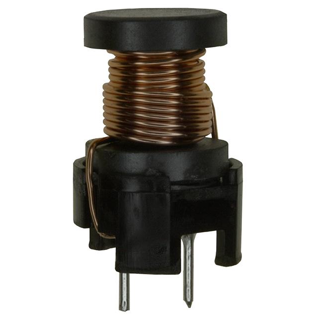


 工商网监
湘ICP备2023018690号
工商网监
湘ICP备2023018690号
