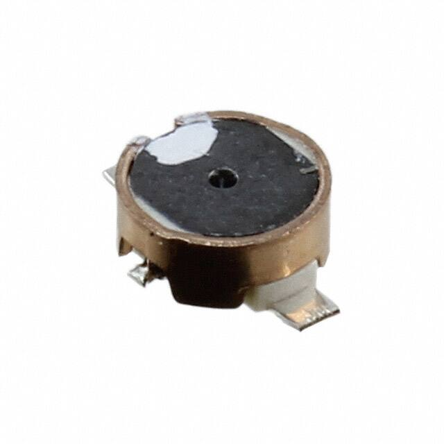
Voltage Step-up Coils
Chip type
ELT3KN series
High inductance Voltage Step-up coil chip series for
piezoelectric buzzers and DC/DC circuitry of EL panels
Features
● Small and thin
● High inductance
● RoHS compliant
Recommended applications
● Piezoelectric buzzer, Booster circuit for EL backlight (Watch, Electric thermometer, Portable device)
Standard packing quantity (Minimum quantity/Packing unit)
●1,000 pcs or 5,000 pcs / reel
Explanation of part numbers
1
2
3
4
5
6
7
8
9
10
E
L
T
3
K
N
0
0
4
C
Product code
Outer size
Construction
Design No.
Packaging
Code
Packaging
B
ø 180 Reel
C
ø370 Reel
5.5±0.2
➄
0.8±0.1
0.10±0.05
4.5±0.2
3.3±0.1
2.5±0.1
1.2±0.1
①
②
④
0.8±0.1
H
⑥
0.10±0.05
0.25±0.05
0.18±0.05
1.1±0.2
(3.1)
4.5±0.2
➄
3.1±0.2
1.2±0.1
(3.3)
5.5±0.2
1.4 max.
0.18±0.05
0.6±0.1
0.85±0.10
3.3±0.1
①
④
④
1.2±0.1
②
1.1±0.2
③
1.1±0.1
(3.3)
(3.1)
D
③
1.2±0.1
3.1±0.2
0.85±0.10
①
5.5±0.2
3.3±0.2
0.6±0.1
0.125±0.050
1.4±0.2
③
0.85±0.10
3.3±0.2
1.2±0.1
②
0.18±0.05
3.3±0.1
①
④
➄
5.5±0.2
B
➄
1.2±0.1
③
1.65±0.20
(3.1)
➄
3.3±0.1
②
2.0±0.2
1.5±0.1
0.18±0.05
③
④
①
E
②
②
④
0.6±0.1
1.2±0.1
3.3±0.2
①
3.3±0.1
C
3.3±0.2
0.6±0.1
3.3±0.1
1.2±0.1
A
0.85±0.10
Dimensions in mm (not to scale)
➄
Part Name: ①Core ②Terminal ③Ring ④Coil ⑤Terminal board ⑥Adhesive
Design and specifications are each subject to change without notice. Ask factory for the current technical specifications before purchase and/or use.
Should a safety concern arise regarding this product, please be sure to contact us immediately.
6-Aug-21
�Voltage Step-up Coils
Standard parts
Inductance
Part No.
(mH)
ELT3KN004◻
ELT3KN007◻
ELT3KN113◻
ELT3KN126◻
ELT3KN142◻
ELT3KN019◻
ELT3KN109◻
ELT3KN114◻
ELT3KN014◻
ELT3KN018◻
ELT3KN028◻
ELT3KN032◻
ELT3KN101◻
ELT3KN104◻
ELT3KN118◻
ELT3KN121◻
ELT3KN122◻
ELT3KN123◻
ELT3KN124◻
ELT3KN127◻
ELT3KN128◻
ELT3KN129◻
ELT3KN130◻
ELT3KN131◻
ELT3KN020◻
ELT3KN111◻
ELT3KN125◻
ELT3KN041◻
ELT3KN042◻
ELT3KN043◻
ELT3KN139◻
ELT3KN140◻
ELT3KN135◻
ELT3KN136◻
ELT3KN137◻
ELT3KN149◻
ELT3KN151◻
ELT3KN152◻
ELT3KN155◻
ELT3KN162◻
ELT3KN163◻
14.00
20.00
1.00
1.50
0.82
14.00
3.80
2.50
30.00
35.00
50.00
25.00
10.00
1.00
2.50
1.00
2.00
1.00
4.00
0.47
0.56
0.68
2.30
2.00
30.00
7.50
4.00
14.00
20.00
12.00
0.68
0.82
1.10
2.00
4.00
0.33
0.56
0.47
1.10
4.00
1.10
DC resistance
Tolerance(%)
(Ω)
125
170
34
49
24
125
115
83
150
235
250
185
285
35
64
22.5
44
25
85
14
15
17
51
44
150
177
85
125
175
117
19
22
32
55
117
11
17
14
38
117
32
±40
±10
±40
±10
±40
±35
±40
±10
±30
±10
±40
±10
Tolerance(%)
DC current
(mA) max.
1.7
1.4
25.0
29.0
30.0
1.7
15.0
15.0
1.9
1.9
1.4
10.0
1.4
30.0
20.0
40.0
20.0
30.0
15.0
50.0
45.0
34.0
23.0
20.0
2.5
10.0
15.0
1.7
1.4
1.7
40.0
30.0
30.0
20.0
15.0
60.0
50.0
50.0
25.0
15.0
30.0
±10
±15
±10
±20
±15
±10
±15
±10
±15
±10
±15
±10
±15
±10
±15
Magnetic
composition
Dimensions
Permalloy ring
A
Brass ring
Permalloy ring
B
Brass ring
Permalloy ring
C
Brass ring
Permalloy ring
D
Brass ring
Permalloy ring
E
Brass ring
H
Ring less
E
Brass ring
“□” shows the packaging specifications.
Applied diagram examples
VO
+1.5 V
For buzzer
For EL DC/DC
+3.0 V
V2
V1
SC
VO
Vi
Vi
Vi
Vi
V1
V2
Load
SC
Design and specifications are each subject to change without notice. Ask factory for the current technical specifications before purchase and/or use.
Should a safety concern arise regarding this product, please be sure to contact us immediately.
6-Aug-21
�Voltage Step-up Coils
Packaging methods (Taping)
● Standard packing quantity
Packaging
Quantity per reel
B
C
1,000 pcs
5,000 pcs
Kind of taping
B 1,000 pcs. Embossed carrier
Embossed carrier taping
● Embossed carrier tape dimensions in mm (not to scale)
t1
Chip pocket
B
F
A
W
E
Sprocket hole
øD0
Chip component
P1
Tape running direction
P2 P3
t2
Unit : mm
Part No.
A
B
W
E
F
P1
P2
P0
øD0
t1
t2
ELT3KN
3.7
6.4
12.0
1.75
5.5
8.0
2.0
4.0
1.5
0.3
2.6
● Reel dimensions in mm (not to scale)
T
C
B
E
D
W
A
t
Unit : mm
Packaging
A
B
C
D
E
W
t
T
B
180
60
13
21
2
13
1.1
15.2
C
370
60
13
21
2
14
2.0
18.0
● Leader Part, Vacant Position
Leader part
200 min.
50 min.
Vacant position
Tape end
50 min.
Vacant position
Design and specifications are each subject to change without notice. Ask factory for the current technical specifications before purchase and/or use.
Should a safety concern arise regarding this product, please be sure to contact us immediately.
6-Aug-21
�Voltage Step-up Coils
Soldering Conditions
Temperature (°C)
Reflow soldering conditions
T3
T2
T1
t1
t2
0
Time
● Pb free solder recommended temperature profile
Voltage Step-up Coils
Part No.
ELT3KN
Preheat
Soldering
T1 [℃]
t1 [s]
T2 [℃]
t2 [s]
150 to 170
60 to 120
230 ℃
30 max.
Peak Temperature
T3
T3 Limit
Time of
Reflow
245 ℃, 10 s 260 ℃, 10 s 2 times max.
Design and specifications are each subject to change without notice. Ask factory for the current technical specifications before purchase and/or use.
Should a safety concern arise regarding this product, please be sure to contact us immediately.
6-Aug-21
�Guidelines and precautions regarding the
technical information and use of our products
described in this online catalog.
■ If you want to use our products described in this online catalog for applications requiring
special qualities or reliability, or for applications where the failure or malfunction of the
products may directly jeopardize human life or potentially cause personal injury
(e.g. aircraft and aerospace equipment, traffic and transportation equipment, combustion
equipment, medical equipment, accident prevention, anti-crime equipment, and/or safety
equipment), it is necessary to verify whether the specifications of our products fit to such
applications. Please ensure that you will ask and check with our inquiry desk as to whether
the specifications of our products fit to such applications use before you use our products.
■ The quality and performance of our products as described in this online catalog only apply
to our products when used in isolation. Therefore, please ensure you evaluate and verify
our products under the specific circumstances in which our products are assembled in your
own products and in which our products will actually be used.
■ If you use our products in equipment that requires a high degree of reliability, regardless
of the application, it is recommended that you set up protection circuits and redundancy
circuits in order to ensure safety of your equipment.
■ The products and product specifications described in this online catalog are subject to
change for improvement without prior notice. Therefore, please be sure to request and
confirm the latest product specifications which explain the specifications of our products in
detail, before you finalize the design of your applications, purchase, or use our products.
■ The technical information in this online catalog provides examples of our products'
typical operations and application circuits. We do not guarantee the non-infringement of
third party's intellectual property rights and we do not grant any license, right, or interest
in our intellectual property.
■ If any of our products, product specifications and/or technical information in this online
catalog is to be exported or provided to non-residents, the laws and regulations of the
exporting country, especially with regard to security and export control, shall be observed.
■ The switchover date for compliance with the RoHS Directive/REACH Regulations varies
depending on the part number or series of our products.
■ When you use the inventory of our products for which it is unclear whether those products
are compliant with the RoHS Directive/REACH Regulation, please select "Sales Inquiry" in the
website inquiry form and contact us.
We do not take any responsibility for the use of our products outside the scope of the
specifications, descriptions, guidelines and precautions described in this online catalog.
01-Oct-19
�Voltage Step-up Coils
Safety Precautions
(Common precautions for Voltage Step-up Coils )
・ When using our products, no matter what sort of equipment they might be used for, be sure to make a written
agreement on the specifications with us in advance. The design and specifications in this catalog are subject to
change without prior notice.
・ Do not use the products beyond the specifications described in this catalog.
・ This catalog explains the quality and performance of the products as individual components. Before use, check and
evaluate their operations when installed in your products.
・ Install the following systems for a failsafe design to ensure safety if these products are to be used in equipment
where a defect in these products may cause the loss of human life or other significant damage, such as damage to
vehicles (automobile, train, vessel), traffic lights, medical equipment, aerospace equipment, electric heating
appliances, combustion/gas equipment, rotating equipment, and disaster/crime prevention equipment.
✽ Systems equipped with a protection circuit and a protection device.
✽ Systems equipped with a redundant circuit or other system to prevent an unsafe status in the event of a single fault.
Precautions for use
1. Operation range and environments
①These products are designed and manufactured for general and standard use in general electronic equipment
(e.g. AV equipment, home electric appliances, office equipment, information and communication equipment)
②These products are not designed for the use in the following special conditions. Before using the products,
carefully check the effects on their quality and performance, and determine whether or not they can be used.
・In liquid, such as water, oil, chemicals, or organic solvent
・In direct sunlight, outdoors, or in dust
・In salty air or air with a high concentration of corrosive gas, such as Cl2,H2S,NH3,SO2,or NOx
・In an environment where these products cause dew condensation
2. Handling
①Do not bring magnets or magnetized materials close to the product. The influence of their magnetic field can
change the inductance value.
②Do not apply strong mechanical shocks by either dropping or collision with other parts.
Excessive schock can damage the part.
3. Resoldering with a soldering iron
①Resoldering should be done within 3 seconds by soldering iron, the temperature with 350 °C or less and should
be cooling down after ward. Both side of terminals shall be fixed closely to PWB. And terminals shall not be
pressed in heating.
Don’t Press
② The wiring tab shall not be held by sharp-edged tool.
Wiring Tab
③ Iron shall not be put to the component itself.
4. Mounting side
① External force must be less than 4.9N while mounting.
② The wiring tab is expose the terminal, so please be careful when you design PWB pattern of coil circumference.
5. Cleaning
If you clean the inductor, please use own your ultrasonic cleaning to check specified conditions.
6. Storage conditions
Normal temperature(‒5 to 35 ℃), normal humidity(85 %RH max.),shall not be exposed to direct sunlight
and harmful gases and care should be taken so as not to cause dew.
<Package markings>
Package markings include the product number, quantity, and country of origin.
In principle, the country of origin should be indicated in English.
1-Apr-20
�