物料型号:
- 0603型:ERA 3Y
- 0805型:ERA 6Y
器件简介:
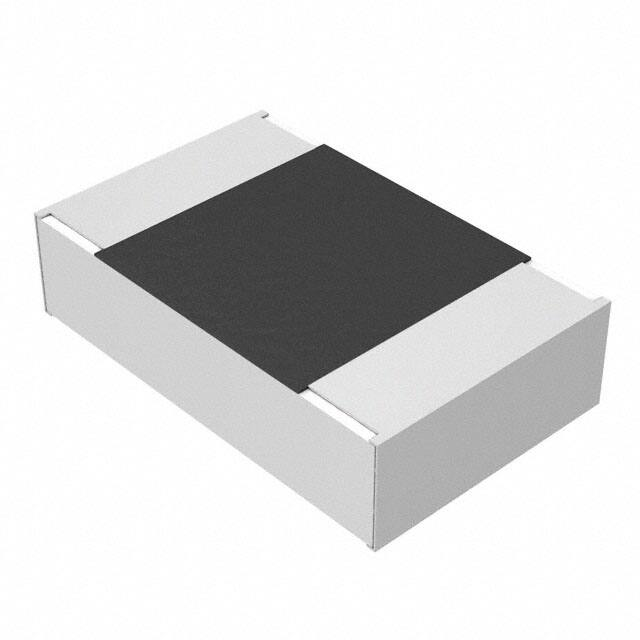
- 小型轻量
- 高可靠性
- 低温度系数(T.C.R.)和电流噪声,优秀的非线性特性
- 适用于回流焊和波峰焊
引脚分配:
- 未提供具体引脚分配信息,但通常片式电阻器为两个端子。
参数特性:
- 电阻公差:±0.1%,±0.5%
- T.C.R.:3Y型为±25ppm/°C,6Y型为±50ppm/°C
- 额定功率:ERA3Y为0.1W,ERA6Y为0.125W
- 最大工作电压:ERA3Y为75V,ERA6Y为100V
功能详解:
- 金属膜片式电阻器具有高可靠性,适合在多种电子设备中使用。
应用信息:
- 适用于需要高稳定性和可靠性的场合。
封装信息:
- 0603型尺寸:1.6mm x 0.8mm
- 0805型尺寸:2.0mm x 1.25mm
- 包装方式:冲孔载体胶带,ERA3Y型为4mm间距,每卷5000件。
设计和规格:
- 设计和规格如有变更,恕不另行通知。购买和/或使用前请向工厂咨询当前技术规格。
安全注意事项:
- 遵守额定功率和环境温度的降额曲线。
- 脉冲负载时,确保脉冲峰值在额定电压内。
- 不要使用卤素或其他高活性助焊剂。
- 使用烙铁时,不要接触电阻器本体。
- 避免过量的焊料导致机械应力增加。
- 避免对电阻器的保护涂层造成损伤。
- 不要对电阻器施加冲击或用硬工具夹持。
- 避免过度弯曲印刷电路板以保护电阻器免受异常应力。
- 不要长时间将电阻器浸泡在溶剂中。