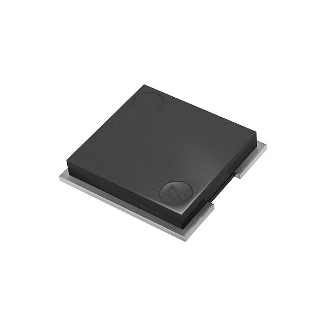
Current Sensing Resistors,
Metal Plate Type
ERJ MS, MB type
ERJ MS4, MB1 series
Features
● Ideal for current sensing solution
● Small case size with high power
● Metal plate bonding technology. Excellent long term stability
● Outer Resin with high heat dissipation. Wide temperature range (-65 ℃ to +170 ℃)
● AEC-Q200 compliant
● RoHS compliant
● ISO9001,ISO/TS16949 certified
■ As for packaging methods, land pattern, soldering conditions and safety precautions,
please see data files.
Explanation of part numbers
1
2
3
4
5
6
7
8
9
10
E
R
J
M
S
4
S
F
2
M
Product code
Type code
Metal plate
chip resistors
Code inch size Electrode type
S4S
2512
Standard
S4H
2512
Narrow
B1S
1020
Standard
Tolerance
F
±1 %
12
U
0
Resistance value
Resistance tolerance
Code
11
Packaging methods
Packaging
Part No.
Embossed carrier taping
4 mm pitch, 2,000 pcs
ERJMS4
Embossed carrier taping
4 mm pitch, 3,000 pcs
ERJMB1
Code
Shown by 3 digits or
letters.Decimal point is
expressed by M as
2.0 mΩ=2M0,
10.0 mΩ=10M
U
Ratings
Part No.
(inch size)
Power rating
(70 ℃)
(W)
Resistance
range
(mΩ)
Resistance
tolerance
(%)
T.C.R.
(×10-6/K)
ERJMS4S
(2512)
3
1, 2, 3, 4
F : ±1
±75
ERJMS4H
(2512)
3
2
5, 6
7, 8, 9, 10
F : ±1
F : ±1
±75
±75
ERJMB1S
(1020)
2
1, 2, 3, 4, 5
F : ±1
±75
Category
temperature
range
(℃)
Terminal temp.
upper limit
(℃)
AEC-Q200
Grade
130
–65 to +170
Grade 0
100
130
✽ Please contact us when resistors of irregular series are needed.
Power derating curve
120
than terminal temperature upper limit value of the
100
rated table, please reduce the rated power according
to the Power Derating Curve shown in the figure on the right.
<Supplemented>
In the case of the temperature measurement of the terminal portion of
the resistor, Please perform under the following conditions.
1)Terminal temperature measurement, please apply the temperature of
the higher of either the left or right electrode upper surface of the resistor.
2)Please measure the temperature of the resistor in the land pattern
Rated load (%)
If the terminal temperature of the resistor is more
-65 ℃
100 ℃
130 ℃
80
60
ERJMS4H
(7 to 10 mΩ)
40
20
0
170 ℃
-80
-40
0
40
80
120
160
200
Terminal temperature (°C)
printed of circuit board and plan to use by real conditions.
Design and specifications are each subject to change without notice. Ask factory for the current technical specifications before purchase and/or use.
Should a safety concern arise regarding this product, please be sure to contact us immediately.
1-Mar-20
�Current Sensing Resistors, Metal Plate Type
Construction
Protective Film
Surface Treatment
(Ni/Sn)
Electrode (Metal)
Resistive Element (Metal Plate)
Dimensions in mm (not to scale), Recommended land pattern
● ERJMS4S/ERJMS4H
● ERJMB1S
T
T
W
W
A
L
L
A
b
c
b
a
c
Land pattern
a
Land pattern
Unit : mm
Dimensions
Part No.
Recommended land pattern
L
W
A
T
a
ERJMS4S
6.40±0.25
3.20±0.25
2.20±0.25
1.20±0.15
2.7
3.4
2.0
120
ERJMS4H
6.40±0.25
3.20±0.25
1.25±0.25
1.20±0.15
1.7
3.4
4.0
115
ERJMB1S
2.55±0.25
5.00±0.25
0.68
+0.15/-0.20
0.90±0.15
1.15
5.5
1.1
40
6000
8000
Change of resistance (%)
Change of resistance (%)
0.5
0
-0.5
-1
-80 -60
-40 -20
0
20
40
60
80
Temperature (℃)
100 120 140 160 180
c
Long-term stability
Typical temp. dependence of electrical resistance
1
b
Mass (Weight)
(Reference)
(g/1000 pcs)
1
ERJMS4SF2M0U 140 ℃ Storage
0.5
0
-0.5
-1
0
2000
4000
Test time (hrs)
Design and specifications are each subject to change without notice. Ask factory for the current technical specifications before purchase and/or use.
Should a safety concern arise regarding this product, please be sure to contact us immediately.
1-Mar-20
�Current Sensing Resistors, Metal Plate Type
Maximum pulse energy respectively pulse power for continuous operation
Referance Data
Condition : Room Temperature, OFF : 10 s, 1000 cycle, Wave form : Square
Change of Resistance = ±1 %
● ERJMS4S/ERJMS4H
100
1000
10
10
ERJMS4S 1mΩ
ERJMS4S
1 mΩ
1
ERJMS4H 5mΩ
ERJMS4H
5 mΩ
0.1
1
0.1
0.01
ERJMS4H 10mΩ
ERJMS4H
10 mΩ
0.01
0.001
0.0001
Power (W)
Pulse Energy (J)
100
0.001
0.001
0.01
0.1
1
0.0001
10
Pulse width (s)
● ERJMB1S
100
1000
Pulse Energy (J)
1
10
1
0.1
ERJMB1S 1 mΩ
ERJMB1S
1 mΩ
0.1
ERJMB1S 3 mΩ
ERJMB1S
3 mΩ
0.01
ERJMB1S 5 mΩ
ERJMB1S
5 mΩ
0.01
0.001
0.0001
Power (W)
10
100
0.001
0.001
0.01
0.1
1
0.0001
10
Pulse width (s)
Design and specifications are each subject to change without notice. Ask factory for the current technical specifications before purchase and/or use.
Should a safety concern arise regarding this product, please be sure to contact us immediately.
1-Mar-20
�Current Sensing Resistors, Metal Plate Type
Performance (AEC-Q200)
● ERJMS4S/ERJMS4H
Performance
Typical value ⊿R
requirements ⊿R
Test item
Thermal shock
Overload
Solderability
Resistance to solvents
±1 %
±0.5 %
Low temperature storage and operation
Resistance to soldering heat
Moisture resistance
Shock
Vibration, High frequency
Life
Storage life at elevated temperature
High temperature characteristics
Frequency characteristics
● ERJMB1
Test condition
0.20 %
0.10 %
> 95% coverage
> 95% coverage
No damage
±0.5 %
±0.5 %
±0.5 %
±0.5 %
±0.5 %
±1 %
±1 %
±0.5 %
< 5 nH
No damage
0.03 %
0.10 %
0.10 %
0.10 %
0.05 %
0.30 %
0.30 %
0.05 %
< 2 nH
–55 ℃ / +155 ℃,1000 cycles
Rated power x 3,5 s
245 ℃, 3 s
MIL-STD-202 method 215, 2.1a, 2.1d
–65 ℃, 24 h
MIL-STD-202 method 210 (260 ℃, 10 s)
MIL-STD-202 method 106
MIL-STD-202 method 213-A
10 to 2000 (Hz)
70 ℃,Rated Power,2000 h
170 ℃, 2000 h
140 ℃, 2000 h
Inductance
Performance
Typical value ⊿R
requirements ⊿R
Test item
Thermal shock
Overload
Solderability
Resistance to solvents
±1 %
±1 %
> 95% coverage
Low temperature storage and operation
Resistance to soldering heat
Moisture resistance
Shock
Vibration, High frequency
Life
Storage life at elevated temperature
High temperature characteristics
Frequency characteristics
No damage
±0.5 %
±0.5 %
±0.5 %
±0.5 %
±0.5 %
±1 %
±1 %
±0.5 %
< 5 nH
Test condition
0.30 %
0.30 %
–55 ℃ / +155 ℃,1000 cycles
Rated power x 2.5,5 s
245 ℃, 3 s
MIL-STD-202 method 215, 2.1a, 2.1d
–65 ℃, 24 h
MIL-STD-202 method 210 (260 ℃, 10 s)
MIL-STD-202 method 106
MIL-STD-202 method 213-A
10 to 2000 (Hz)
70 ℃,Rated Power,2000 h
170 ℃, 2000 h
140 ℃, 2000 h
Inductance
> 95% coverage
No damage
0.03 %
0.10 %
0.10 %
0.10 %
0.05 %
0.30 %
0.30 %
0.05 %
< 2 nH
Temperature rise
● ERJMS4HF5M0U
100
90
80
70
Temperature Rise (°C)
Temperature Rise (°C)
80
70
60
50
40
30
20
10
0
● ERJMB1SF3M0U
60
50
40
30
20
10
0
0
1
2
Power(W)
3
①
②
Base material : FR-4 (t 1.6 mm)
0
1
2
Power(W)
Resistor
①
②
Soldering
PWB
Copper Thickness : 70 µm, Two layer
Sense terminal-Layout
Land
Sense terminal
Design and specifications are each subject to change without notice. Ask factory for the current technical specifications before purchase and/or use.
Should a safety concern arise regarding this product, please be sure to contact us immediately.
1-Mar-20
�Guidelines and precautions regarding the
technical information and use of our products
described in this online catalog.
■ If you want to use our products described in this online catalog for applications requiring special
qualities or reliability, or for applications where the failure or malfunction of the products may directly
jeopardize human life or potentially cause personal injury (e.g. aircraft and aerospace equipment,
traffic and transportation equipment, combustion equipment, medical equipment, accident prevention,
anti-crime equipment, and/or safety equipment), it is necessary to verify whether the specifications of
our products fit to such applications. Please ensure that you will ask and check with our inquiry desk
as to whether the specifications of our products fit to such applications use before you use our products.
■ The quality and performance of our products as described in this online catalog only apply to our
products when used in isolation. Therefore, please ensure you evaluate and verify our products under
the specific circumstances in which our products are assembled in your own products and in which our
products will actually be used.
■ If you use our products in equipment that requires a high degree of reliability, regardless of the
application, it is recommended that you set up protection circuits and redundancy circuits in order
to ensure safety of your equipment.
■ The products and product specifications described in this online catalog are subject to change for
improvement without prior notice. Therefore, please be sure to request and confirm the latest product
specifications which explain the specifications of our products in detail, before you finalize the design
of your applications, purchase, or use our products.
■ The technical information in this online catalog provides examples of our products' typical operations
and application circuits. We do not guarantee the non-infringement of third party's intellectual property
rights and we do not grant any license, right, or interest in our intellectual property.
■ If any of our products, product specifications and/or technical information in this online catalog is to
be exported or provided to non-residents, the laws and regulations of the exporting country,
especially with regard to security and export control, shall be observed.
■ The switchover date for compliance with the RoHS Directive/REACH Regulations varies depending
on the part number or series of our products.
■ When you use the inventory of our products for which it is unclear whether those products are
compliant with the RoHS Directive/REACH Regulation, please select "Sales Inquiry" in the website
inquiry form and contact us.
We do not take any responsibility for the use of our products outside the scope of the
specifications, descriptions, guidelines and precautions described in this online catalog.
16-Apr-21
�Fixed Resistors
Application Guidelines (Fixed Resistors)
Safety precautions
• When using our products, no matter what sort of equipment they might be used for, be sure to make a written
agreement on the specifications with us in advance. The design and specifications in this catalog are subject to
change without prior notice.
• Do not use the products beyond the specifications described in this catalog.
• This catalog explains the quality and performance of the products as individual components. Before use, check
and evaluate their operations when installed in your products under the actual conditions for use.
• Install the following systems for a failsafe design to ensure safety if these products are to be used in equipment
where a defect in these products may cause the loss of human life or other significant damage, such as
damage to vehicles (automobile, train, vessel), traffic lights, medical equipment, aerospace equipment,
electric heating appliances, combustion/gas equipment, rotating equipment, and disaster/crime prevention
equipment.
✽ Systems equipped with a protection circuit and a protection device.
✽ Systems equipped with a redundant circuit or other system to prevent an unsafe status in the event of a single fault.
✽ Systems equipped with an arresting the spread of fire or preventing glitch.
Precautions for use
• These products are designed and manufactured for general and standard use in general elec tron ic equipment.
(e.g. AV equipment, home electric appliances, office equipment, information and communication equipment)
For applications in which special quality and reliability are required, or if the failure or malfunction of the
products may directly jeopardize life or cause threat of personal injury (such as for aircraft and aerospace
equipment, traffic and transport equipment, combustion equipment, medical equipment, accident prevention
and anti-theft devices, and safety equipment), please be sure to consult with our sales representative in
advance and to exchange product specifications which conform to such applications.
• These products are not intended for use in the following special conditions. Before using the products, carefully
check the effects on their quality and performance, and determine whether or not they can be used.
1. In liquid, such as water, oil, chemicals, or organic solvent.
2. In direct sunlight, outdoors, or in dust.
3. In salty air or air with a high concentration of corrosive gas, such as Cl2, H2S, NH3, SO2, or NOX .
4. Electric Static Discharge (ESD) Environment.
These components are sensitive to static electricity and can be damaged under static shock (ESD).
Please take measures to avoid any of these environments.
Smaller components are more sensitive to ESD environment.
5. Electromagnetic and Radioactive Environment.
Avoid any environment where strong electromagnetic waves and radiation exist.
6. In an environment where these products cause dew condensation.
7. Sealing or coating of these products or a printed circuit board on which these products are mounted, with
resin or other materials.
• These products generate Joule heat when energized. Carefully position these products so that their heat will
not affect the other components.
• Carefully position these products so that their temperatures will not exceed the category temperature range
due to the effects of neighboring heat-generating components. Do not mount or place heat-generating
components or inflammables, such as vinyl-coated wires, near these products.
• Note that non-cleaning solder, halogen-based highly active flux, or water-soluble flux may deteriorate the
performance or reliability of the products.
• Carefully select a flux cleaning agent for use after soldering. An unsuitable agent may deteriorate the
performance or reliability. In particular, when using water or a water-soluble cleaning agent, be careful not to
leave water residues. Otherwise, the insulation performance may be deteriorated.
• Do not apply flux to these products after soldering. The activity of flux may be a cause of failures in these
products.
• Refer to the recommended soldering conditions and set the soldering condition. High peak temperature or
long heating time may impair the performance or the reliability of these products.
• Recommended soldering condition is for the guideline for ensuring the basic characteristics of the products,
not for the stable soldering conditions. Conditions for proper soldering should be set up according to individual
conditions.
• Do not reuse any products after removal from mounting boards.
• Do not drop these products. If these products are dropped, do not use them. Such products may have
received mechanical or electrical damage.
• If any doubt or concern to the safety on these products arise, make sure to inform us immediately and
conduct technical examinations at your side.
01-Oct-19
�Fixed Resistors
Precautions for storage
The performance of these products, including the solderability, is guaranteed for a year from the date of
arrival at your company, provided that they remain packed as they were when delivered and stored at
a temperature of 5 °C to 35 °C and a relative humidity of 45 % to 85 %.
Even within the above guarantee periods, do not store these products in the following conditions.
Otherwise, their electrical performance and/or solderability may be deteriorated, and the packaging
materials (e.g. taping materials) may be deformed or deteriorated, resulting in mounting failures.
1. In salty air or in air with a high concentration of corrosive gas, such as Cl2, H2S, NH3, SO2, or NOX .
2. In direct sunlight.
<Package markings>
Package markings include the product number, quantity, and country of origin.
In principle, the country of origin should be indicated in English.
AEC-Q200 Compliant
The products are tested based on all or part of the test conditions and methods defined in AEC-Q200.
Please consult with Panasonic for the details of the product specification and specific evaluation test results,
etc., and please review and approve Panasonic's product specification before ordering.
01-Oct-19
�Surface Mount Resistors
Application Guidelines (Surface Mount Resistors)
The following are precautions for individual products. Please also refer to the common precautions for Fixed
Resistors in this catalog.
1. Take measures against mechanical stress during and after mounting of Surface Mount Resistors
(hereafter called the resistors) so as not to damage their electrodes and protective coatings.
Be careful not to misplace the resistors on the land patterns. Otherwise, solder bridging may occur.
2. Keep the rated power and ambient temperature within the specified derating curve.
Some circuit boards, wiring patterns, temperatures of heat generated by adjacent components, or
ambient temper a tures can become factors in the rise of the temperature of the resistors, regardless of
the level of power applied. Therefore, check the conditions before use and op timize them so as not to
damage the boards and peripheral components.
Make sure to contact us before using the resistors under special conditions.
3. If a transient load (heavy load in a short time) like a pulse is expected to be applied, check and evaluate
the operations of the resistors when installed in your products before use. Never exceed the rated power.
Otherwise, the performance and/or reliability of the resistors may be impaired.
4. Transient voltage
If there is a possibility that the transient phenomenon (significantly high voltage applied in a short time)
may occur or that a high voltage pulse may be applied, make sure to evaluate and check the
characteristics of resistors mounted on your product rather than only depending on the calculated power
limit or steady-state conditions.
5. If the resistors are to be used in high frequency circuits, carefully check the operation before use.
Such circuits change the electrical characteristics of the resistors.
6.Before using halogen-based or other high-activity flux, check the possible effects of the flux residues on the
performance and reliability of the resistors.
7. When soldering with a soldering iron, never touch the resistors'bodies with the tip of the soldering iron.
When using a soldering iron with a high temperature tip, finish soldering as quickly as possible
(within three seconds at 350 °C max.).
8. Mounting of the resistors with excessive or insufficient wetting amount of solder may affect the
connection reliability or the performance of the resistors. Carefully check the effects and apply a proper
amount of solder for use.
9. When the resistors' protective coatings are chipped, flawed, or removed, the characteristics of the
resistors may be impaired. Take special care not to apply mechanical shock during automatic mounting
or cause damage during handling of the boards with the resistors mounted.
10. Do not apply shock to the resistors or pinch them with a hard tool (e.g. pliers and tweezers). Otherwise,
the resistors' protective coatings and bodies may be chipped, affecting their performance.
11. Avoid excessive bending of printed circuit boards in order to protect the resistors from abnormal stress.
12. Do not immerse the resistors in solvent for a long time.
Before using solvent, carefully check the effects of immersion.
13. Do not apply excessive tension to the terminals.
01-Oct-19
�


 工商网监
湘ICP备2023018690号
工商网监
湘ICP备2023018690号

