Detector Switches/ESE11
5N Detector Switches
Type:
ESE11
Features
Wide range of customizable fea tures including
operational directions
Light operating force
Wide available range for reflow soldering
Recommended Applications
Detection of media in portable electronic equipment
Detector Switch es
Explanation of Part Numbers
1
R a ting
2
3
4
5
6
9
50 0 mΩ max. (Initial)
Ins ula tion R es is ta nc e
10 0 MΩ min. (100 Vdc)
Dielec tric Withs ta nding Volta ge
10 0 Va c for 1 minute
O pera ting F orc e
3 50 mN ma x. (F ull Travel)
·
·
·
·
·
Type
Type
Type
Type
Type
SV
4.9 mm
MV
4.9 mm (MV2, 7 : 5.4 mm)
SH
5.25 mm
MH
4.25 mm
HS, SF 3.6 mm
P oles a nd T hrows
Full Travel (Pushing distance)
8
50 µA 3 Vdc to 10 mA 5 Vdc (R es is tive loa d)
C onta c t R es is ta nc e
Mounting Height
7
1-pole 1-throw
·
·
·
·
·
Type
Type
Type
Type
Type
SV
MV
SH
MH
HS, SF
6.1 mm (2.4 mm)
6.1 mm (2.4 mm)
3.0 mm (2.4 mm)
1.7 mm (2.4 mm)
6.3 mm (2.4 mm)
O pera ting L ife
50 0 0 0 c yc les min.
Tempera ture R a nge
‒10 °
C to +70 °
C
H ea t R es is ta nc e
+8 0 °
C for 9 6 hours
L ow Tempera ture R es is ta nc e
‒25 °
C for 9 6 hours
H umidity R es is ta nc e
+4 0 °
C 9 0 % to 95 % R H for 9 6 hours
Design and speci cations are each subject to change without notice. Ask factory for the current technical speci cations before purchase and/or use.
Should a safety concern arise regarding this product, please be sure to contact us immediately.
00
– ES43 –
Oct. 2012
�Detector Switches/ESE11
ESE11SV □
ESE11MV □
ESE11SH □
ESE11MH □
ESE11HS □
ESE11SF □
Minimum Quantity/Packing Unit
200 pcs.
Polyethylene Bag (Bulk)
800 pcs.
Embossed Taping (Reel Pack)
ESE11MV □T
(Excluding : ESE11MV2)
Quantity/
Carton
ESE11MH □T
1500 pcs.
Embossed Taping (Reel Pack)
ESE11SV □
ESE11MV □
ESE11SH □
ESE11MH □
ESE11HS □
ESE11SF □
10000 pcs.
Polyethylene Bag (Bulk)
ESE11MV2
8000 pcs.
Polyethylene Bag (Bulk)
4800 pcs.
Embossed Taping (Reel Pack)
ESE11MV □T
(Excluding : ESE11MV2)
9000 pcs.
Embossed Taping (Reel Pack)
ESE11MH □T
Dimensions in mm (not to scale)
ESE11SV1 For wave soldering
1-pole 1-throw
No. 2
ESE11MV1
1.0
3.0
5.2
6.4
5.2
6.4
A
A
2.45
1.27
0.8
ON starting
position
Ho
(2.45)
1.4
0.95
7.75
0.8
1.4
2.0 2.0
le
6.1
1.0
1.4
0
1.2 ‒0.1
3.25
3.35
1.4
2.3
1.0
4.9
1.85
1.3
8.5 0.2
7.75
2-f
1.75
3.3
Lever center
Full travel
ON starting
position
1.27
6.1
8.5
(3.3)
.05
+0
0
+0
0 .05
1.65
1.65 0.1
.25
.10
0.1
0
f 1.2 ‒0.1
f1
4‒
f1
(2.7)
4.9
1.0
1.0
0.95
2.3
1.0
Full travel
1.0
Vertical Type
1.0
For reflow soldering
1-pole 1-throw
2.2
3.0
Gold plating
ESE11MV5 1.51.75
2.2
No. 1
PWB mounting hole for reference
View from A
PWB mounting hole for reference
View from A
Design and speci cations are each subject to change without notice. Ask factory for the current technical speci cations before purchase and/or use.
Should a safety concern arise regarding this product, please be sure to contact us immediately.
00
– ES44 –
Oct. 2012
�Detector Switches/ESE11
Dimensions in mm (not to scale)
ESE11MV9 For reflow soldering
1-pole 1-throw
No. 3
Gold plating
ESE11MV13 1.5
No. 4
1.5
1.75
1.0
2.2
3.0
2.2
3.0
1.75
1.0
5.2
6.4
5.2
6.4
A
A
1.65
Full travel
1.27
ON starting position
1.27
Full travel
ON starting
position
Ho
le
1.4
3.25
3.35
Gold plating
ESE11SH6
1.0
3.0
4.65
5.4
2.35
0.1
1.0
5.36
6.5
1.75
3.0
4.65
5.4
3.2
2.35
0.1
0.8
1.5
1.5
2-f 1.20
Lever center
1.0
5.36
1.75
2-f 1.10
2.35
2-f 1.10
(1.65)
1.0
5.1
3.1
1.0
f 1.2
(5.4)
(5.4)
2.35
1.75
Full travel
ON starting
position
8.5
8.5
5.1
3.1
f 1.2
5.36
10.25
1.27
1.0
1.5
3.2
0.8
5.36
6.5
1.0
1.0
6.4
5.6
4.2
3.0
3.15
5.25
1.27
1.5
Full travel
ON starting
position
For wave soldering
1-pole 1-throw
A
1.65
5.9
5.7
4.75
1.0
1.75
ESE11SH2C
6.4
5.6
4.2
1.65
No. 6
3.0
3.15
5.25
A
ESE11SH1C For wave soldering
1-pole 1-throw
5.9
5.7
4.75
Gold plating
ESE11SH5
3.25
3.35
PWB mounting hole for reference
View from A
PWB mounting hole for reference
View from A
No. 5
0.8
8.6 max.
5.4
7.5
11.0
1.3
1.4
1.4
1.85
0
f 1.2 ‒0.1
2.0 2.0
2-f
1.75
1.4
+0
0 .05
4‒1.4
.30
1.65
2.0 2.0
2‒
f1
4‒1.4
7.75
0.8
6.1
8.5
4.9
1.85
0
f 1.2 ‒0.1
1.0
1.75
Detector Switch es
1.65
Horizontal Type
1.65
1.0
1.0
Vertical Type
1.0
For reflow soldering
1-pole 1-throw
ESE11MV2
(1.65)
2-f 1.20
Lever center
PWB mounting hole for reference
View from A
PWB mounting hole for reference
View from A
Design and speci cations are each subject to change without notice. Ask factory for the current technical speci cations before purchase and/or use.
Should a safety concern arise regarding this product, please be sure to contact us immediately.
00
– ES45 –
Oct. 2012
�Detector Switches/ESE11
Dimensions in mm (not to scale)
5.36
0.6
Full travel
ON starting
position
View from side A
7.65±0.05
f 1.30
+0.05
0
3.0
.2
2.1
4.25
C0
1.0
1.0
1.5
View from side B
6.3
7.95
8.7
7.0
6.25
4.6
A
0.1
1.65
5.85
2.85±0.05
6.15
+0.05
0
View from side A
PWB mounting hole for reference
B
6.15
4.50±0.05
M2 screw hole f 1.30
hole
Full travel
ON starting
position
1.0
3.6
‒0 0
.1
0.9
4.5
5.85
1.15
6.3
7.95
8.7
7.0
6.25
4.6
1.5
5.85
1.15±0.05
hole
.0
2.85
1.0
5.85
2.85±0.05
+0.05
0
f2
1.6
1.75
2.25
M2 screw hole
4.6
Full travel
2.2
1.27
1.5
1.0
6.15
M2 screw hole f 1.30
3.35
.0
.0
6.15
4.50±0.05
0
0.6 ‒0.05
1.7
1.0
ON starting
position
0
f 1.2 ‒0.1
6.15
0.1
1.65
f1
1.5
A
5.4
4.4
3.2
2.9
4.1
f1
1.6
1.75
2.25
B
0
3.0
3.6
3.75
1.0
5.2
1.0
3.6
0.9
4.5
2.85
1.15
‒0 0
.1
.7
ESE11HS2 For manual soldering
1-pole 1-throw
No. 10
8.6
Full travel
2.2
1.27
1.5
.0
1.27
4.6
ON starting
position
1.0
f2
Full travel
ON starting position
7.65
4.5
0
f 1.2 ‒0.1
0
f 1.2 ‒0.1
6.15
1.75
5.36
3.0
3.6
3.75
5.2
2f0
M2 screw hole
5.85
4.1
1.4
2.2
1.0
0.5
1.2
1.5
ESE11HS1 For manual soldering
1-pole 1-throw
8.6
5.85
6.4
5.6
3.7 ‒0.7
ON starting position
7.65
4.5
0
f 1.2 ‒0.1
0.7
A
1.15±0.05
0
0
1.6
1.75
PWB mounting hole for reference
View from A
3.0
C0
Full travel
No. 9
1.65
0.2
0.6 ‒0.05
1.7
2.1
4.25
0.5
0.2
1.5
5.36
Horizontal Type
5.4
4.4
3.2
2.9
1.27
6.4
5.6
0.7
0.8
1.5
A
5.0
1.6
1.5
1.4
5.36
1.0
0.1
f 1.2
1.0
1.2
1.75
2f0
.70
PWB mounting hole for reference hol
e
View from A
.2
1.65
7.6
0.1
f 1.2
0.6
6.7
4.9
2.2
1.6
1.5
1.4
6.7
5.0
1.6
1.75
0.8
4.9
7.6
Gold plating
ESE11MH4
1.4
Gold plating
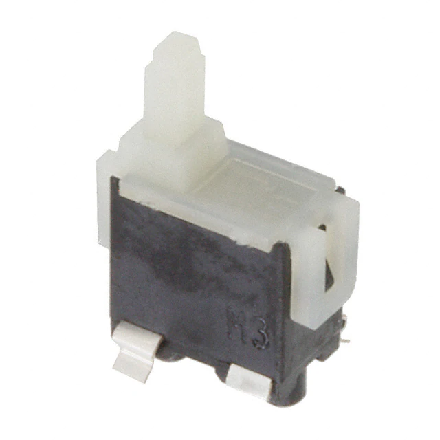
ESE11MH3
ESE11MH2 For reflow soldering
1-pole 1-throw
No. 8
3.4
For reflow soldering
1-pole 1-throw
ESE11MH1
3.4
No. 7
hole
7.65±0.05
f 1.30
+0.05
0
hole
View from side B
PWB mounting hole for reference
Design and speci cations are each subject to change without notice. Ask factory for the current technical speci cations before purchase and/or use.
Should a safety concern arise regarding this product, please be sure to contact us immediately.
00
– ES46 –
Oct. 2012
�Detector Switches/ESE11
Dimensions in mm (not to scale)
ESE11SF1A For manual soldering
1-pole 1-throw
No. 11
0.6
0.5
1.0
0.8
(2.6)
1.0 3.6 1.0
3.0
0.6
0.5
0
f 1.2 ‒0.1
f 1.2
5.2
1.65
A
1.5
2.2
1.27
Full travel
ON starting
position
+0.05
0
0
f 1.3
1.3 +0.5
0
8.7±0.2
1.8 +0.5
0
3.35±0.05
1.3 +0.5
0
0.1
1.65
Detector Switch es
1.5
.0
1.75
2.25
f1
1.6
1.5
0.9
6.3
7.95
8.7
4.5
7.0
5.35
1.5
0.7
3.6
1.0
3.35
Horizontal Type
8.0
PWB mounting hole for reference
(PWB thickness=0.80±0.05)
View from A
8.00 +0.05
0
Design and speci cations are each subject to change without notice. Ask factory for the current technical speci cations before purchase and/or use.
Should a safety concern arise regarding this product, please be sure to contact us immediately.
00
– ES47 –
Oct. 2012
�Detector Switches/ESE11
Circuit Diagram
MH, SH Type
MV, S V Type
1-pole 1-throw (N.O)
S F, HS Type
1-pole 1-throw (N.O)
Common
terminal
Frame
Frame
C
Common
terminal
1-pole 1-throw (N.O)
C
Lever
Common
terminal
C
C
C
Common
terminal
Common
terminal
Standard Reel Dimensions in mm (not to scale)
Ta ping R eel
E mbos s ed C a rrier Ta ping
Non-packed portion
(160 mm min.)
13.5
16.0±0.3
Carrier tape
.1
+0 0
(7.5)
END
.5
f 380±2.0
P=12.0±0.1
Drawing direction
TOP
4.0±0.1
2.0±0.1
Pilot holes Leading portion 400 mm min.
f1
1.75±0.1
ESE11MV1T, ESE11MV5T, ESE11MV9T
Packed portion
Non-packed portion
(100 mm min.)
Cover tape
16.4
P=12.0±0.1
Drawing direction
TOP
4.0±0.1
2.0±0.1
Pilot holes Leading portion 400 mm min.
13.5
END
Carrier tape
.1
+0 0
.5
f1
16.0±0.3
(7.5)
1.75±0.1
ESE11MH1T, ESE11MH2T
Non-packed portion
(160 mm min.)
Packed portion
Non-packed portion
(100 mm min.)
Cover tape
Design and speci cations are each subject to change without notice. Ask factory for the current technical speci cations before purchase and/or use.
Should a safety concern arise regarding this product, please be sure to contact us immediately.
00
– ES48 –
Oct. 2012
�
很抱歉,暂时无法提供与“ESE-11MV5T”相匹配的价格&库存,您可以联系我们找货
免费人工找货