Detector Switches/ESE24
ESE24 Detector Switches
Type:
ESE24
Bidirectional operation, midpoint auto-return Type
Features
Recommended Applications
A lever-type detector switch with high reliability using
sliding mechanical contacts
Long over-travel (through-operation available)
Used as an operation switch (an input device)
Detection of media in portable electronic equipment
(CD-ROM, DVD, Digital still cameras, etc.)
Operating switches for other electronic equipment.
Explanation of Part Number
1
2
3
4
5
6
7
6th & 7th
SV
SH
MV
MH
Rating
Contact Resistance
Insulation Resistance
Dielectric Withstanding Voltage
Operating Force
Poles and Throws
Full Travel (Pushing distance)
Operating Life
Temperature Range
Heat Resistance
Low Temperature Resistance
Humidity Resistance
Quantity/Carton
9
Mounting Method & Style
Vertical type for wave soldering
Horizontal type for wave soldering
Vertical type for reflow soldering
Horizontal type for reflow soldering
50 μA 3 V DC to 10 mA 5 V DC (Resistive load)
50 0 mΩ max. (Initial)
100 MΩ min. (at 100 V DC for 1 minute)
Mounting Height
Minimum Quantity/Packing Unit
8
ESE24MH, MV, SV, SH
ESE24MH□T
ESE24MV□T
ESE24MH, MV, SV, SH
ESE24MH□T
ESE24MV□T
100 V AC (50 Hz or 60 Hz) for 1 minute
3 5 0 m N m a x.
· ESE24SV Type 5.6 mm
· ESE24SH Type 4.65 mm
· ESE24MV Type 5.6 mm
· ESE24MH Type 3.0 mm
1-pole 2-throws (OFF at midpoint)
· ESE24SV Type
6.1 mm (2.45 mm)
· ESE24SH Type 2.6 mm (2.45 mm)
· ESE24MV Type 6.1 mm (2.45 mm)
· ESE24MH Type 1.4 mm (2.45 mm)
50 ,0 0 0 cycles min.
–10 °C to +70 °C (Standard), –40 °C to +85 °C (Automotive)
+80 °C for 9 6 hours
–25 °C for 9 6 hours
+40 °C 9 0 % to 95 % RH for 9 6 hours
1
200 pcs. Polyethylene Bag (Bulk)
2
1,000 pcs. Embossed Taping (Reel Pack)
500 pcs. Embossed Taping (Reel Pack)
10,000 pcs. Polyethylene Bag (Bulk)
6,000 pcs. Embossed Taping (Reel Pack)
3,000 pcs. Embossed Taping (Reel Pack)
1 ESE24SH type: 160 pcs. (Polyethylene Bag), 8,000 pcs. (Reel Pack)
2 ESE24SV, ESE24SH are excluded
Design and specifications are each subject to change without notice. Ask factory for the current technical specifications before purchase and/or use.
Should a safety concern arise regarding this product, please be sure to contact us immediately.
2017.06
industrial.panasonic.com/ac/e/
–1–
Panasonic Corporation 2017
ANCTB54E 201706-Fd
�Detector Switches/ESE24
Dimensions in mm (not to scale)
No. 2
ESE24SH1 Horizontal type for wave soldering
1-pole 2-throws
+0
0 .05
2φ1
.2
0
2.55
1.6
2.50 2.50
29˚24' 68˚2
6'
No. 3
2
2.5
1.0
2.1
1.0
3.0
3.5
2.9
3.8
3.0
No. 4
ESE24MH1 Horizontal type for reflow soldering
1-pole 2-throws
ESE24MH1T (Embossed Taping)
7.50
0.25
PWB mounting hole for reference
(Tolerance: ±0.05)
5.5
3-1.40
2.50 2.50
PWB mounting hole for reference
(Tolerance: ±0.05)
1.5
1.5
7.5
4.3
2.7
6'
1.2
0.2
0.9
29˚24' 68˚2
3.0
2.0
1.0
φ1.0
4.0
5.4
1
C
2
2.5
2.5
1.0
0.5
0.
2
29˚24' 68˚2
6'
3.0
1.0
0.25 (Rotative center)
7.5
4.3
2.7
1.60
2-φ
0.7
0
6-1.40
2.50 2.50
C
2.5
positioning boss
0.6
2.5
1.0
1.4 (Full position)
3.35 (ON starting position)
1.6
1.5
4.7
3.85
2
2.35 to 2.85 (Pushing position)
3.60
5.80
C
5.6
6.1(Full position)
8.05(ON starting position)
1.0
8.55
1
4.45 (Rotative center)
7.05 to 7.55 (Pushing position)
(H
7.25
2.00
4.50
2.00
7.25
0.25
)
2-φ
1.
5.50
ole
10
+0
0 .05
ESE24MV1 Vertical type for reflow soldering
1-pole 2-throws
ESE24MV1T (Embossed Taping)
1.65
1.60
C
2.5
4.65
3.65
1.0
0.3
1.4
2.7
1
PWB mounting hole for reference
(Pitch tolerance: ±0.05)
(PWB thickness=0.8)
5.05
0.2
2.6 (Full position)
4.55 (ON starting position)
7.5
4.3
2.7
8.55
'
3.55 to 4.05 (Pushing position)
0.95 (Rotative center)
3.0
1.0
0.2
5.6
6.1 (Full position)
26
8.05 (ON starting position)
6 8˚
29˚24'
5
.0
+0 0
PWB mounting hole for reference
(Pitch tolerance: ±0.05)
(PWB thickness=0.8)
7.5
4.3
2.7
2.50 2.50
7.16
0
.1
φ1
3-
7.05 to 7.55 (Pushing position)
4.45 (Rotative center)
2.90
1
8.4
7.25
2.5
2.5
C
2
2.75
6φ1
.1
0
+0
0 .05
ESE24SV3 Vertical type for wave soldering
1-pole 2-throws
2.20
No. 1
0.1
Positioning boss
Design and specifications are each subject to change without notice. Ask factory for the current technical specifications before purchase and/or use.
Should a safety concern arise regarding this product, please be sure to contact us immediately.
Panasonic Corporation Electromechanical Control Business Division
industrial.panasonic.com/ac/e/
–2–
Panasonic Corporation 2017
ANCTB54E 201706-Fd
�Detector Switches/ESE24
Circuit Diagram
1-pole 2-throws (N . O)
F
b
a
Terminal No.
1
Lever
position
c
2
F
a
b
1
2
C
Common
terminal
Standard Reel Dimensions in mm (not to scale)
Taping Reel
Embossed Carrier Taping
1.75±0.1
Non-packed portion
(160 mm min.)
4.0±0.1
END
Carrier tape 2.0±0.1
Non-packed portion
(160 mm min.)
Drawing direction
.1
TOP
+00
.5
1
Leading portion 400 mm min.
φ
Pilot holes
21.3
24.0±0.3
(11.5)
24.4
1.75±0.1
φ380.0±2.0
(11.5)
P=16.0±0.1
4.0±0.1
END
Carrier tape 2.0±0.1
Packed portion
Non-packed portion
(100 mm min.)
Cover tape
P=16.0±0.1
.1
+00
Drawing direction
Leading portion
400 mm min.
TOP
9.9±0.2
0.4
21.5
24.0±0.3
.5
φ1Pilot holes
Packed portion
Non-packed portion
(100 mm min.)
Cover tape
Design and specifications are each subject to change without notice. Ask factory for the current technical specifications before purchase and/or use.
Should a safety concern arise regarding this product, please be sure to contact us immediately.
Panasonic Corporation Electromechanical Control Business Division
industrial.panasonic.com/ac/e/
–3–
Panasonic Corporation 2017
ANCTB54E 201706-Fd
�
很抱歉,暂时无法提供与“ESE-24CSV3”相匹配的价格&库存,您可以联系我们找货
免费人工找货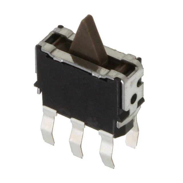


 工商网监
湘ICP备2023018690号
工商网监
湘ICP备2023018690号
