Detector Switches/ESE31
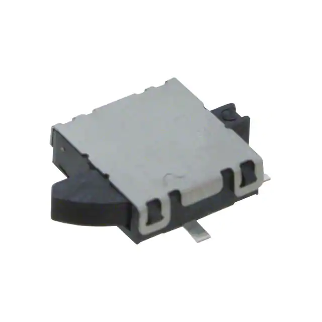
ESE31 Detector Switches
Type:
ESE31
Features
Recommended Applications
Increased the mounting strength Mounting strength: 80 N
Decreased the profile of the switch body Height: 1.7 mm
Increased the contact reliability.
Detection of media in portable electronic equipment
Explanation of Part Numbers
1
2
3
4
5
6
8
9
Design No
Product Code
6th
L
R
7
Type
Left-side operation type
Right-side operation type
50 μA 3 V DC to 10 mA 5 V DC (Resistive load)
Rating
50 0 mΩ max. (Initial)
Contact Resistance
Insulation Resistance
100 MΩ min. (at 100 V DC for 1 minute)
Dielectric Withstanding Voltage
100 V AC (50 Hz or 60 Hz) for 1 minute
Operating Force
3 9 0 m N m a x.
Mounting Height
1.7 mm
Poles and Throws
1-pole 1-throw
Full Travel
(Pushing distance)
3.2 mm (2.15 mm)
Operating Life
Temperature Range
50 ,00 0 cycles min.
–10 °C to +70 °C (Standard), –40 °C to +85 °C (Automotive)
Heat Resistance
+85 °C for 9 6 hours
Low Temperature Resistance
– 40 °C for 9 6 hours
Humidity Resistance
+6 0 °C 9 0 % to 95 % RH for 9 6 hours
2,50 0 pcs. Embossed Taping (Reel Pack)
Minimum Quantity/Packing Unit
Quantity/Carton
15,0 0 0 pcs.
Design and specifications are each subject to change without notice. Ask factory for the current technical specifications before purchase and/or use.
Should a safety concern arise regarding this product, please be sure to contact us immediately.
2017.06
industrial.panasonic.com/ac/e/
–1–
Panasonic Corporation 2017
ANCTB50E 201706-Fd
�Detector Switches/ESE31
Dimensions in mm (not to scale)
No. 2
ESE31L11T
1-pole 1-throw
5.75
5.75
R3.8
2.8
Horizontal
direction
1.1
1 1.2
3.5
7.45
1.2 1
3.5
7.45
0.5±0.05
φ1.3
6.0
2.5
1.6
1.2
9.0
5.6
φ1.1+0.05
–0
1.6
1.2
2.5
φ1.3
5.5
2.5
C
2-
2.5
9.0
5.6
2-φ1±0.05
.2
2-φ1±0.05
5.5
C0
φ1.1+0.05
–0
0.5
1.6
2-
0.
2
5.9
1
5.9
0.5±0.05
1
1.6
6.0
0.5
1.7
1.5
1.1
4.35
5.4
(8.65)
3.2
Vertical direction
ON starting position
1.1
(8.65)
5.4
4.35
Horizontal
ON position
measuring
position
Horizontal
ON position
measuring
position
5.45±0.1
Horizontal
direction
(2.5)
0.6
(1) 1.21.05
1.45
2.5±0.1
2.3
5.2
R0.2
Vertical
direction
Measuring position 0.42
Horizontal ON position 0.26±0.25
0.14
Operation point
0.42 Measuring position
0.26±0.25 Horizontal ON position
Operation point
0.14
2.8
1.7 Vertical direction
1.5 ON starting position
1.1
R3.8
Vertical direction
1-pole 1-throw
ESE31R11T
3.2
5.45±0.1
5.2
2.3
2.5±0.1
1.45
(1) 1.2 1.05
0.6
(2.5)
No. 1
1.1+0.05
–0
1.1+0.05
–0
1.7
6.1
1.7
6.1
PWB mounting hole for reference
PWB mounting hole for reference
Circuit Diagram
1-pole 1-throw (N . O)
ESE31L11T
ESE31R11T
Common terminal C
Common terminal C
C Common terminal
Common terminal C
1
C Common terminal
1
C Common terminal
Standard Reel Dimensions in mm (not to scale)
Taping Reel
16.4
END
P=12.0±0.1 Drawing direction
4.0±0.1
TOP
Pilot holes
2.0±0.1
Leading portion 400 mm min.
13.5
16.0±0.3
.1
+0 0
Carrier tape
5
1.
φ
7.5±0.1
1.75±0.1
φ380.0±2.0
Embossed Carrier Taping
Non-packed portion
(160 mm min.)
Packed portion
Non-packed
portion
(100 mm min.)
Cover tape
Design and specifications are each subject to change without notice. Ask factory for the current technical specifications before purchase and/or use.
Should a safety concern arise regarding this product, please be sure to contact us immediately.
Panasonic Corporation Electromechanical Control Business Division
industrial.panasonic.com/ac/e/
–2–
Panasonic Corporation 2017
ANCTB50E 201706-Fd
�
很抱歉,暂时无法提供与“ESE-31L15T”相匹配的价格&库存,您可以联系我们找货
免费人工找货- 国内价格 香港价格
- 2500+3.499812500+0.45410
- 5000+3.329045000+0.43194
- 7500+3.238037500+0.42014
- 12500+3.1323512500+0.40642
- 17500+3.0680017500+0.39807
- 25000+3.0041825000+0.38979
- 国内价格 香港价格
- 1+6.353501+0.82436
- 10+5.4127510+0.70230
- 25+5.0366725+0.65351
- 100+4.49636100+0.58340
- 250+4.16474250+0.54037
- 500+3.93249500+0.51024
- 1000+3.718711000+0.48250