Light Touch Switches/EVPBF
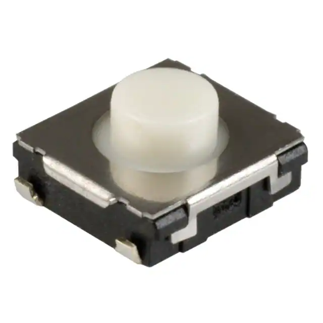
6mm Square Middle Travel SMD
Light Touch Switch
Type:
EVPBF
■ Features
● External dimensions : 6.0 mm×6.0 mm, Height 2.5 mm
(Excluding the push plate, Middle Travel)
● Middlestroke travel type
■ Recommended Applications
● Operating switches for other electronic equipment
● Operation switches for PC mouse
● Car audio systems
● Game
■ Explanation of Part Numbers
1
2
3
4
Product Code
5
Type
6
7
Operating
Force
Ground
terminal
8
9
10
11
12
A
0
0
0
Product Height
■ Specifications
Travel Type
Type
Rating
Contact Resistance
Insulation Resistance
Electrical
Dielectric Withstanding Voltage
Bouncing
Operating Force
Mechanical
Travel
Endurance Operating Life
Operating Temperature
Storage Temperature
Minimum Quantity/Packing Unit
Quantity/Carton
Middlestroke Travel
Snap action/Push-on type SPST
10 μA 2 V DC to 20 mA 15 V DC (Resistive load)
500 mΩ max.
100 MΩ min. (at 100 V DC)
250 V AC for 1 minute
10 ms max. (ON, OFF)
2.0 N, 3.5 N
2.0 N : 0.25 mm, 3.5 N : 0.32 mm
2.0 N : 1,000,000 cycles min. , 3.5 N : 100,000 cycles min.
–40 °C to +85 °C
–40 °C to +85 °C (Bulk)
–20 °C to +60 °C (Taping)
3,000 pcs. Embossed Taping (Reel Pack)
15,000 pcs.
Note: Non washable
Design and specifications are each subject to change without notice. Ask factory for the current technical specifications before purchase and/or use.
Should a safety concern arise regarding this product, please be sure to contact us immediately.
2018.11
industrial.panasonic.com/ac/e/
–1–
Panasonic Corporation 2018
ANCTB97E 201811-Fd
�Light Touch Switches/EVPBF
■ Dimensions in mm (not to scale)
EVPBF
General dimension tolerance : ± 0.2
( )dimensions are reference dimensions.
Middlestroke 5ravel
With J-bent terminals
3.5
2.5
B'
B
A'
A
(3.6)
6.0
4.0
0.8
6.0
φ3.4
φ3.7
(4.0)
(4.4)
(5.1)
(0.8)
Knob
(6.6)
(6.0)
(2.8)
No sordering
A'
3.0
5.0
B
(6.0)
(2.8)
B'
A
3.0
8.5
Circuit Diagram
PWB land pattern for reference
: Recommended land pattern area.
: No soldering area.
t Any land pattern or via holes shall not be
provided at
area.
t If it's necessary to design land pattern or
via holes at
area,
please apply resist to them to protect their
metal part completely.
t�*G�UIFJS�NFUBM�QBSUT�BSF�OPU�QSPUFDUFE
completely,short circuit failure may occur
by solder ball.
t�#FTJEF
�UIFSF�TIPVME�CF�DPOWFYPDPODBWF�CZ
designing additional pattern,
it may cause swith tilt, influence on
TPMEFS�BCJMJUZ�PS�GMVY�JOUSVTJPO
after reflow soldering.
t�5IFSFGPSF
�QMFBTF�TUVEZ�BOZ�JOGMVFODF�PG
additional land pattern or via holes at
area in advance.
Part Numbers
Push Plate Color Ground 5erminal
Operating Force
Height
EVPBFAC1A000
2.0 N
3.5 mm
Gray
Without
1,000,000 cycles
Operating Life
EVPBF6C1A000
3.5 N
3.5 mm
Gray
Without
100,000 cycles
Design and specifications are each subject to change without notice. Ask factory for the current technical specifications before purchase and/or use.
Should a safety concern arise regarding this product, please be sure to contact us immediately.
Panasonic Corporation Electromechanical Control Business Division
industrial.panasonic.com/ac/e/
–2–
Panasonic Corporation 2018
ANCTB97E 201811-Fd
�Light Touch Switches/EVPBF
■ Recommended Reflow Soldering Conditions
Operation Top (°C)
MAX.
260
Fan or Normal Temp.
230
180
150
(Normal Temp.)
90±30
40±10
Soldering Time (s)
● Embossed Carrier Taping
Tape width=12.0 mm
Feeding hole
t1
Chip pocket
P2 P0
E
φD0
B
F
W
A
t2
P1
Chip component
Tape running direction
Taping condition : Lack of products in the middle of taping should be
one MAX, but total quantity specified in the
specifications should be secured.
Peeling off strength of top tape : It should be within 0.2N to 1.0N at
165 degree in peeling off angle.
Joint of carrier tape : One joint per one reel may exist.
Unit: mm
Part No.
EVPBF
Height
3.5
A
6.7±0.2
B
7.4±0.2
W
12.0±0.3
F
E
P1
P2
5.5±0.1 1.75±0.10 8.0±0.1
■ Recommended Shape of Test Pole
2.0±0.1
P0
D0 Dia
4.0±0.1
+0.1
0
1.5
t1
t2
0.30±0.05 3.7±0.1
■ Recommended Operating Conditions
0.3 mm max.
φ4 +0.5
–0
Test pole
Leaning angle range
90 °±4 °
(vertical direction)
Switch
R0.1 mm±0.05 mm
Mounting surface
Design and specifications are each subject to change without notice. Ask factory for the current technical specifications before purchase and/or use.
Should a safety concern arise regarding this product, please be sure to contact us immediately.
Panasonic Corporation Electromechanical Control Business Division
industrial.panasonic.com/ac/e/
–3–
Panasonic Corporation 2018
ANCTB97E 201811-Fd
�Guidelines and cautions for using the product technical information and
the products displayed on this material
ƪThe products described on this material were designed and manufactured for standard applications such as
general electronics devices, office equipment, data and communications equipment, measuring instruments,
household appliances and audio-video equipment. For special applications in which quality and reliability are
required, or if the failure or malfunction of the products may directly jeopardize life or cause threat of personal
injury (such as for aircraft and aerospace equipment, traffic and transport equipment, combustion equipment,
medical equipment, accident prevention and anti-theft devices, and safety equipment), please use only after
your company has sufficiently tasted our products' suitability for that application.
ƪWhen using our products in equipment that requires a high degree of reliability, regardless of the application,
it is recommended that you use protection circuits and redundancy circuits for equipment safety and test for
safety.
ƪThe products and product specifications described on this material are subject to change for improvement
without prior notice. Therefore, be sure to request and confirm in advance the most current specifications,
which explain the specifications in detail, before the final stage of your design, purchasing or use for any
application.
ƪThe technical information on this material provides examples of the products' typical operations and
application circuits. It is not intended to guarantee the non-infringement of or grant license for intellectual
property rights of this company or any third party.
ƪPermission must be obtained from the Japanese government if products, products specifications and technical
information on this material that are subject to the "Foreign Exchange and Foreign Trade Law" are to be
exported or taken out of Japan.
ƪThe information contained on this material may not be reprinted or reproduced whether wholly or in part,
without the prior written permission of Panasonic Corporation.
Safety Precautions
When using our products, no matter what sort of equipment they might be used for, be sure to
confirm the applications and environmental conditions with our specifications in advance.
Please contact ..........
Electromechanical Control Business Division
1006, Oaza Kadoma, Kadoma-shi, Osaka 571-8506, Japan
industrial.panasonic.com/ac/e/
©Panasonic Corporation 2018
ANCTB97E-1 201811-Fd
Specifications are subject to change without notice.
�