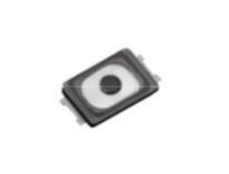
Light Touch Switches/EVPAW
3.0 mm×2.0 mm SMD Light Touch Switches
Type:
EVPAW
■ Features
● External dimensions : 3.0 mm×2.0 mm, Height 0.6 mm
● High operability
Equipped with an actuator (push plate)
● IP67 characteristic
■ Recommended Applications
● Operation switches for portable electronic equipment
(Mobile phone, Portable audio)
■ Explanation of Part Numbers
1
2
3
4
5
&
7
1
"
8
Product Code
6
7
Type
8
9
Height
7 th
A
D
Type
Terminal without cutout type
Terminal with cutout type
■ Specifications
Type
Snap action/Push-on type SPST
Rating
10 μA 2 Vdc to 20 mA 15 Vdc (Resistive load)
Contact Resistance
Electrical
Insulation Resistance
Dielectric Withstanding Voltage
Bouncing
Mechanical
Endurance
IP67(✽1)
50 MΩ min. (at 100 Vdc)
250 Vac for 1 minute
10 ms max. (ON, OFF)
Operating Force
1.6 N, 2.4 N, 3.3 N
Travel
1.6 N, 2.4 N : 0.13 mm
3.3 N : 0.15 mm
Operating Life
1.6 N, 2.4 N : 500000 cycles min.
3.3 N : 300000 cycles min.
IP6x (Dust resistance)
Dust : Talc (Type4) 8h
IPx7 (Water resistance)
Immersion depth : 1 m 30 min.
Operating Temperature
Storage Temperature
Minimum Quantity/Packing Unit
Quantity/Carton
500 mΩ max.
–40 °C to +85 °C
–40 °C to +85 °C (Bulk)
–20 °C to +60 °C (Taping)
10000 pcs. Embossed Taping (Reel Pack)
50000 pcs.
Note: Non washable
(✽1) IP67 : Switch shall not be operated during test.
Water or dust ingress shall be limited enough to prevent deleterious effect to the switch function.
However, IP67 shall be guaranteed under single product state,
then there is a possibility that IP67 performance become impaired depending on your mounting condition or usage.
So, please ask us in advance, if the switch is applied to important usage for water and dust resistant.
Design and specifications are each subject to change without notice. Ask factory for the current technical specifications before purchase and/or use.
Should a safety concern arise regarding this product, please be sure to contact us immediately.
02
Apr. 2015
�Light Touch Switches/EVPAW
■ Dimensions in mm (not to scale)
EVPAW
(Embossed Taping)
Terminal without cutout type
General dimension tolerance : ± 0.05
( )dimensions are reference dimensions.
This reference specifications are subject to change.
0.6±0.1
without the film
and remainder
of the gate
2
2-1.3
(0.385)
(f0.85)
A
A'
3.5
2-3.69
2-2.85
2-1.45
3
Without film
2-0.25
0.04±0.03
Circuit diagram
0.1 max.
Stencil mask plan
A
A'
2-1.5
0.1 max.
3.8
2.7
PWB land pattern for reference
Soldering thickness t=0.08±0.01
=Soldering failure may occur depending on applied
solder amount, so, please consider to use
our recommended stencil and land pattern desing.
Part Numbers
Operating Force
Height
Operating Life
EVPAWBA2A
1.6 N
0.6 mm
500000 cycles
EVPAWCA2A
2.4 N
0.6 mm
500000 cycles
EVPAWEA2A
3.3 N
0.6 mm
300000 cycles
Design and specifications are each subject to change without notice. Ask factory for the current technical specifications before purchase and/or use.
Should a safety concern arise regarding this product, please be sure to contact us immediately.
02
Apr. 2015
�Light Touch Switches/EVPAW
■ Dimensions in mm (not to scale)
EVPAW
(Embossed Taping)
Terminal with cutout type
General dimension tolerance : ± 0.05
( )dimensions are reference dimensions.
This reference specifications are subject to change.
2
2-1.3
(2-0.8)
without the film
and remainder
of the gate
0.6±0.1
(0.385)
3.3
There should be cutout
on the terminal
(f0.85 )
A
A'
Circuit diagram
0.04±0.03
3
Without film
3.5
The thickness of the solder stencil shall be 0.1 mm,
and the opening ratio of the solder stencil to a land
pattern shall be 60 to 100 % (recommend 80 %.)
3.8
2.7
0.1max.
0.1max.
No Soldering area
A’
2-1.5
A
(2)
(1.9)
Land pattern plan
=Soldering failure may occur depending on applied
solder amount, so, please consider to use our
recommended stencil and land pattern desing.
: Recommended land pattern area
: No soldering area
• Any land pattern or via holes shall not be provided
at
area.
• If it's necessary to design land pattern or via holes
at
area, please apply resist to them to protect
their metal part completely.
• If their metal parts are not protected completely,
short circuit failure may occur,
• Besides, there should be convexoconcave by
designing additional pattern, it may cause swith tilt,
influence on solder-ability or flux intrusion after
reflow soldering.
• Therefore, please study any influence of additioan
land pattern or via holes at
area in advance.
Part Numbers
Operating Force
Height
Operating Life
EVPAWBD4A
1.6 N
0.6 mm
500000 cycles
EVPAWCD4A
2.4 N
0.6 mm
500000 cycles
EVPAWED4A
3.3 N
0.6 mm
300000 cycles
Design and specifications are each subject to change without notice. Ask factory for the current technical specifications before purchase and/or use.
Should a safety concern arise regarding this product, please be sure to contact us immediately.
02
Apr. 2015
�Light Touch Switches/EVPAW
■ Recommended Reflow Soldering Conditions
Operation Top (°C)
MAX.
260
Fan or Normal Temp.
230
180
150
(Normal Temp.)
90±30
40±10
Soldering Time (s)
✽ Reflow temperature may vary by location even in the same reflow condition.
Please check the reflow temperature at terminals and at the top of a switch
to make sure the both temperatures are withiin the specification.
If even one of them is out of the specifications, please adjust.
● Embossed Carrier Taping
Tape width=12.0 mm
Chip pocket
E
F
J
H
A
K
C
I
D
fG
B
Feeding hole
t
Tape running direction
Taping condition : Lack of products in the middle of taping should be
one MAX, but total quantity specified in the
specifications should be secured.
Peeling off strength of top tape : It should be within 0.2N to 1. ON at
165 degree in peeling off angle.
Joint of carrier tape : One joint per one reel may exist.
Unit: mm
Part No.
Height
EVPAW
0.6
A
B
C
12.0±0.3 1.75±0.10 5.5±0.1
D
E
F
G
H
I
8.0±0.1
4.0±0.1
2.0±0.1
1.5±0.3
3.8±0.2
Item
A
J
K
2.3±0.2 0.75±0.20 (10.25)
t
0.3+0.15
–0.10
● Standard Reel Dimensions in mm (not to scale)
G
E
C
B
D
E
013.0±0.5
021.0±1.0
2.0±0.5
B
Rate (mm) 0380.0±2.0 080.0±1.0
C
D
A
Item
F
G
Rate (mm)
13.5±1.0
17.5±1.0
F
Design and specifications are each subject to change without notice. Ask factory for the current technical specifications before purchase and/or use.
Should a safety concern arise regarding this product, please be sure to contact us immediately.
02
Apr. 2015
�


 工商网监
湘ICP备2023018690号
工商网监
湘ICP备2023018690号

