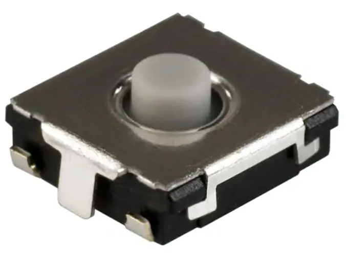
Tactile Switches
6 mm Square Thin Type SMD
Type
EVQP0, EVQQ2, EVQ6Q2, EVQ7Q2, EVPBT
FEATURES
●●E
� xternal dimensions : 6.5 mm × 6.0 mm,
Height 1.8 mm ( Excluding the push plate )
●●W
� ith or without ground terminal, height,
operating force
●●O
� verstroke travel
RECOMMENDED APPLICATIONS
●●O
� perating switches for other electronic
equipment
●●Operation switches for PC mouse
●●Game
EXPLANATION OF PART NO.
1
E
2
V
3
Q
Product Code
4
P
Q
6
5
0/2
7
6
7
8
9
Q
Product Height Push Plate Color
Type Operating Force
Ground Terminal
Height:4.3mm
1
2
3
4
5
E
V
P
B
T
Product Code
2020.11
Operation Force
industrial.panasonic.com/ac/e/
6
7
8
9
10
11
12
0
0
0
Type・
Product Height・Plate color
Ground Terminal
ー1ー
Panasonic Corporation 2020
ANCTB12E 202011
�Tactile Switches EVQP0, Q2, 6Q2, 7Q2, EVPBT
SPECIFICATIONS
■■Characteristics
Travel Type
Short Push Travel
Type
Overstroke Travel
Snap action/Push-on type SPST
Rating
10 µA 2 V DC to 20 mA 15 V DC ( Resistive load )
Contact Resistance
Electrical
Max. 100 mΩ
Insulation Resistance
Mechanical
Endurance
Min. 100 MΩ ( at 100 V DC )
Dielectric Withstanding Voltage
250 V AC for 1 minute
Bouncing
Max. 10 ms ( ON, OFF )
Operating Force
0.5 N, 0.8 N, 1.0 N, 1.3 N,1.6 N, 2.6 N, 3.5 N
0.5 N, 0.8 N, 1.0 N
1.3 N, 1.6 N, 2.6 N, 3.5 N
Travel
0.5
1.0
2.6
3.5
Operating Life
0.6 N, 1.0 N
0.2 mm
0.25 mm
0.3 mm
N, 0.8 N
: Min. 2,000,000 cycles
N, 1.3 N, 1.6 N : Min. 1,000,000 cycles
N
: Min. 200,000 cycles
N
: Min. 100,000 cycles
0.6 N: Min. 2,000,000 cycles
1.0 N: Min. 1,000,000 cycles
Operating Temperature
-40℃ to +85℃
Storage Temperature
-40℃ to +85℃ ( Bulk )
-20℃ to +60℃ ( Taping )
Minimum Quantity / Packing Unit
Quantity / Carton
H = 2.0 mm
4,000 pcs.
Embossed Taping ( Reel Pack )
H = 2.5 mm, 3.1 mm, 4.3 mm
2,000 pcs.
Embossed Taping ( Reel Pack )
H = 2.0 mm
20,000 pcs.
H = 2.5 mm, 3.1 mm, 4.3 mm
10,000 pcs.
Note: Non washable
Unit: mm
CAD The CAD data of the products with a“CAD”mark can be downloaded from our Website.
Overstroke travel
With J-bent terminals
Without
Ground Terminal
External dimensions
CAD
Circuit diagram
6.5
φ3
B
B'
A
A'
B'
B
A'
A
PWB land pattern for reference
(General dimension tolerance: ±0.2)
( ) dimensions are reference dimensions.
4.0
(6.6)
(0.8)
1.8
H
φ2
Min. 1
■■�EVQP0
0.8
4.0
6.0
DIMENSIONS
(3.2)
Part Numbers
Operating Force
H=Height
Push Plate Color
EVQP0N02B
0.6 N
2.5 mm
Blue
EVQP0Q02Q
1.0 N
2.5 mm
Gray
Panasonic Corporation Electromechanical Control Business Division
industrial.panasonic.com/ac/e/
ー2ー
Ground Terminal
Without
Panasonic Corporation 2020
(3.6)
(3.2)
Operating Life
2,000,000 cycles
1,000,000 cycles
ANCTB12E 202011
�Tactile Switches EVQP0, Q2, 6Q2, 7Q2, EVPBT
External dimensions
CAD
6.5
Ⓐ
B
φ3
Circuit diagram
(5.1)
(4.4)
(3.9)
B'
(3.6)
0.8
4.0
6.0
Overstroke travel
With J-bent terminals
With
Ground Terminal
φ2
Operating 0.05±0.1
part
B'
A
A'
PWB land pattern for reference
A'
A
B
Ⓑ
Min. 1
■■�EVQP0
Min. 1
(General dimension tolerance: ±0.2)
( ) dimensions are reference dimensions.
Part Numbers
Operating Force
H=Height
Push Plate Color
EVQP0P02B
0.6 N
2.5 mm
Blue
EVQP0S02Q
1.0 N
2.5 mm
Gray
Short travel
With J-bent terminals
Without
Ground Terminal
(3.3)
(3.2)
(3.6)
Ground Terminal
Circuit diagram
6.5
φ3.8
Operating Life
1,000,000 cycles
External dimensions
CAD
(3.2)
2,000,000 cycles
With
B
B'
A
A'
B'
B
0.8
4.0
6.0
■■�EVQQ2/6Q2
Min. 1
The shape of the mounting base is
either Ⓐ or Ⓑ.
1.8
H
3.3
(0.8)
(6.6)
4.0
Ground terminal
A'
A
PWB land pattern for reference
(General dimension tolerance: ±0.2)
( ) dimensions are reference dimensions.
4.0
(6.6)
(0.8)
1.8
H
Min. 1
φ3
(3.2)
Operating Force
H=Height
EVQQ2B01W
0.5 N
2.0 mm
2,000,000 cycles
EVQQ2B02W
0.5 N
2.5 mm
2,000,000 cycles
EVQQ2B03W
0.5 N
3.1 mm
2,000,000 cycles
EVQ6Q201W
0.8 N
2.0 mm
2,000,000 cycles
EVQ6Q202W
0.8 N
2.5 mm
2,000,000 cycles
EVQ6Q203W
0.8 N
3.1 mm
2,000,000 cycles
EVQQ2F01W
1.0 N
2.0 mm
1,000,000 cycles
EVQQ2F02W
1.0 N
2.5 mm
1,000,000 cycles
EVQQ2F03W
1.0 N
3.1 mm
1,000,000 cycles
EVQQ2K01W
1.3 N
2.0 mm
EVQQ2K02W
1.3 N
2.5 mm
EVQQ2K03W
1.3 N
3.1 mm
1,000,000 cycles
EVQQ2P01W
1.6 N
2.0 mm
1,000,000 cycles
EVQQ2P02W
1.6 N
2.5 mm
1,000,000 cycles
EVQQ2P03W
1.6 N
3.1 mm
1,000,000 cycles
EVQQ2U01W
2.6 N
2.0 mm
200,000 cycles
EVQQ2U02W
2.6 N
2.5 mm
200,000 cycles
EVQQ2U03W
2.6 N
3.1 mm
200,000 cycles
EVQQ2Y01W
3.5 N
2.0 mm
100,000 cycles
EVQQ2Y02W
3.5 N
2.5 mm
100,000 cycles
EVQQ2Y03W
3.5 N
3.1 mm
100,000 cycles
industrial.panasonic.com/ac/e/
ー3ー
Ground Terminal
(3.2)
Part Numbers
Panasonic Corporation Electromechanical Control Business Division
Push Plate Color
(3.6)
Operating Life
1,000,000 cycles
White
Without
Panasonic Corporation 2020
1,000,000 cycles
ANCTB12E 202011
�Tactile Switches EVQP0, Q2, 6Q2, 7Q2, EVPBT
External dimensions
CAD
Circuit diagram
(5.1)
(4.4)
(3.9)
6.5
φ3.8
Ⓐ
B
B'
(3.6)
0.8
4.0
6.0
Short travel
With J-bent terminals
With
Ground Terminal
A'
A
φ3
Operating
part
0.05±0.1
B
B'
A
A'
PWB land pattern for reference
Ⓑ
Min. 1
■■�EVQQ2/7Q2
Min. 1
(6.6)
Part Numbers
Operating Force
(General dimension tolerance: ±0.2)
( ) dimensions are reference dimensions.
H=Height
Push Plate Color
Min. 1
3.3
(0.8)
1.8
H
The shape of the mounting base is
either Ⓐ or Ⓑ.
4.0
Ground terminal
(3.3)
(3.2)
(3.6)
Ground Terminal
(3.2)
Operating Life
EVQQ2D01W
0.5 N
2.0 mm
2,000,000 cycles
EVQQ2D02W
0.5 N
2.5 mm
2,000,000 cycles
EVQQ2D03W
0.5 N
3.1 mm
2,000,000 cycles
EVQ7Q201W
0.8 N
2.0 mm
2,000,000 cycles
EVQ7Q202W
0.8 N
2.5 mm
2,000,000 cycles
EVQ7Q203W
0.8 N
3.1 mm
2,000,000 cycles
EVQQ2H01W
1.0 N
2.0 mm
1,000,000 cycles
EVQQ2H02W
1.0 N
2.5 mm
1,000,000 cycles
EVQQ2H03W
1.0 N
3.1 mm
1,000,000 cycles
EVQQ2M01W
1.3 N
2.0 mm
EVQQ2M02W
1.3 N
2.5 mm
EVQQ2M03W
1.3 N
3.1 mm
1,000,000 cycles
EVQQ2S01W
1.6 N
2.0 mm
1,000,000 cycles
EVQQ2S02W
1.6 N
2.5 mm
1,000,000 cycles
EVQQ2S03W
1.6 N
3.1 mm
1,000,000 cycles
EVQQ2W01W
2.6 N
2.0 mm
200,000 cycles
EVQQ2W02W
2.6 N
2.5 mm
200,000 cycles
EVQQ2W03W
2.6 N
3.1 mm
200,000 cycles
EVQQ2201W
3.5 N
2.0 mm
100,000 cycles
EVQQ2202W
3.5 N
2.5 mm
100,000 cycles
EVQQ2203W
3.5 N
3.1 mm
100,000 cycles
Panasonic Corporation Electromechanical Control Business Division
industrial.panasonic.com/ac/e/
ー4ー
1,000,000 cycles
White
With
Panasonic Corporation 2020
1,000,000 cycles
ANCTB12E 202011
�Tactile Switches EVQP0, Q2, 6Q2, 7Q2, EVPBT
External dimensions
CAD
Circuit diagram
(5.1)
(4.4)
6.5
φ3.8
(3.9)
B
B'
A
A'
0.8
4
6
Short travel
With J-bent terminals
Without
Ground Terminal
4.3
1.8
A'
4.0
Piece weight: about 0.16 g
(0.8)
A
(3.6)
Knob color: BLACK
(6.6)
B'
PWB land pattern for reference
Knob
φ3
B
Min. 1
■■�EVPBT
Solder thickness: t = 0.15±0.03
Note) Knob colour may be different
depending on the location of
the manufacturing process.
(General dimension tolerance: ±0.2)
( ) dimensions are reference dimensions.
(3.2)
Part Numbers
Operating Force
H=Height
0.5 N
4.3 mm
2,000,000 cycles
EVPBT2C4A000
0.8 N
4.3 mm
2,000,000 cycles
EVPBT3C4A000
1.0 N
4.3 mm
EVPBT4C4A000
1.3 N
4.3 mm
EVPBT5C4A000
1.6 N
4.3 mm
1,000,000 cycles
EVPBT6C4A000
2.6 N
4.3 mm
200,000 cycles
EVPBT7C4A000
3.5 N
4.3 mm
100,000 cycles
Without
(5.1)
(4.4)
(3.9)
Ⓐ
B
B'
A'
φ3
Ground terminal
A
A'
PWB land pattern for reference
Ⓑ
Min. 1
3.3
(6.6)
The shape of the mounting base is
either Ⓐ or Ⓑ.
(3.3)
Knob color: BLACK
(3.2)
(3.6)
Min. 1
4.3
(0.8)
1.8
4.0
Knob
B'
(3.6)
A
B
Min. 1
0.05±0.1
6.5
φ3.8
1,000,000 cycles
Circuit diagram
External dimensions
CAD
Operating Life
1,000,000 cycles
Black
0.8
4
6
Short travel
With J-bent terminals
With
Ground Termina
Ground Terminal
(3.6)
EVPBT1C4A000
■■�EVPBT
Push Plate Color
(3.2)
(3.2)
Piece weight: about 0.16 g
Solder thickness: t = 0.15±0.03
Note) Knob colour may be different
depending on the location of
the manufacturing process.
(General dimension tolerance: ±0.2)
( ) dimensions are reference dimensions.
Part Numbers
Operating Force
H=Height
EVPBT1J4A000
0.5 N
4.3 mm
2,000,000 cycles
EVPBT2J4A000
0.8 N
4.3 mm
2,000,000 cycles
EVPBT3J4A000
1.0 N
4.3 mm
EVPBT4J4A000
1.3 N
4.3 mm
EVPBT5J4A000
1.6 N
4.3 mm
1,000,000 cycles
EVPBT6J4A000
2.6 N
4.3 mm
200,000 cycles
EVPBT7J4A000
3.5 N
4.3 mm
100,000 cycles
Panasonic Corporation Electromechanical Control Business Division
industrial.panasonic.com/ac/e/
ー5ー
Push Plate Color
Ground Terminal
Operating Life
1,000,000 cycles
Black
With
Panasonic Corporation 2020
1,000,000 cycles
ANCTB12E 202011
�Tactile Switches EVQP0, Q2, 6Q2, 7Q2, EVPBT
External dimensions
CAD
Circuit diagram
(5.1)
(4.4)
(3.9)
6.5
B'
A
Knob
(3.6)
φ3
(3.2)
B
B
B'
A
A'
PWB land pattern for reference
A'
4.5
φ3.8
3.5
(4.15)
Short travel
With straight terminals
Without
Ground Terminal
4.8
6
■■�EVPBT
4.3
1.8
8
4-1.6
Solder thickness: t = 0.15±0.03
8.1
4-1.4
Knob color: BLACK
Piece weight: about 0.16 g
Note) Knob colour may be different
depending on the location of
the manufacturing process.
(General dimension tolerance: ±0.2)
( ) dimensions are reference dimensions.
Part Numbers
Operating Force
H=Height
EVPBT1A4A000
0.5 N
4.3 mm
2,000,000 cycles
EVPBT2A4A000
0.8 N
4.3 mm
2,000,000 cycles
EVPBT3A4A000
1.0 N
4.3 mm
EVPBT4A4A000
1.3 N
4.3 mm
EVPBT5A4A000
1.6 N
4.3 mm
1,000,000 cycles
EVPBT6A4A000
2.6 N
4.3 mm
200,000 cycles
EVPBT7A4A000
3.5 N
4.3 mm
100,000 cycles
Without
External dimensions
6.5
φ3.8
Circuit diagram
(5.1)
(4.4)
0.05±0.1
Ⓐ
B
(3.9)
B'
(3.2)
A
Knob
Ground terminal
(3.6)
φ3
1,000,000 cycles
Ⓑ
B
B'
A
A'
PWB land pattern for reference
Min. 1
A'
4.5
CAD
Operating Life
1,000,000 cycles
Black
3.5
(4.15)
4.8
6
Short travel
With straight terminals
With
Ground Terminal
Ground Terminal
Min. 1
■■�EVPBT
Push Plate Color
4-1.6
The shape of the mounting base is
either Ⓐ or Ⓑ.
3.3
8.1
Knob color: BLACK
8
4-1.4
4.3
1.8
(3.3)
Piece weight: about 0.16 g
Solder thickness: t = 0.15±0.03
Note) Knob colour may be different
depending on the location of
the manufacturing process.
(General dimension tolerance: ±0.2)
( ) dimensions are reference dimensions.
Part Numbers
Operating Force
H=Height
EVPBT1G4A000
0.5 N
4.3 mm
Push Plate Color
Ground Terminal
2,000,000 cycles
Operating Life
2,000,000 cycles
EVPBT2G4A000
0.8 N
4.3 mm
EVPBT3G4A000
1.0 N
4.3 mm
EVPBT4G4A000
1.3 N
4.3 mm
EVPBT5G4A000
1.6 N
4.3 mm
1,000,000 cycles
EVPBT6G4A000
2.6 N
4.3 mm
200,000 cycles
EVPBT7G4A000
3.5 N
4.3 mm
100,000 cycles
Panasonic Corporation Electromechanical Control Business Division
industrial.panasonic.com/ac/e/
ー6ー
1,000,000 cycles
Black
With
Panasonic Corporation 2020
1,000,000 cycles
ANCTB12E 202011
�Tactile Switches EVQP0, Q2, 6Q2, 7Q2, EVPBT
EMBOSSED TAPE DIMENSIONS
Unit: mm
■■Specifications for taping
●● Part Numbers: EVQP0 / Height: 2.5 mm
J
E
F
φG
t
H
I
A
C
B
D
Tape running direction
Note) 1: Peeling off strength of top tape : It should be within
0.2N to 1.0N at 165 degree in peeling off angle.
2: Taping condition : Lack of products in the middle of
taping should be one MAX, but total quantity specified in the
specifications should be secured.
3: Joint of carrier tape: One joint per one reel may exist.
Unit: mm
A
B
C
D
E
F
G
H
I
J
t
12 ±0.3
1.75 ±0.1
5.5 ±0.1
8 ±0.1
4 ±0.1
2 ±0.1
1.5 +0.1
-0
6.7 ±0.2
7.4 ±0.2
2.8 ±0.2
0.3 ±0.05
●●Part Numbers: �EVQQ2 / Height: 2.0 mm●
EVQ6Q2
2.0 mm●
EVQ7Q2
2.0 mm
E
F
φG
J
t
H
I
A
C
B
D
Tape running direction
Note) 1: Peeling off strength of top tape : It should be within
0.2N to 1.0N at 165 degree in peeling off angle.
2: Taping condition : Lack of products in the middle of
taping should be one MAX, but total quantity specified in the
specifications should be secured.
3: Joint of carrier tape: One joint per one reel may exist.
Unit: mm
A
B
C
D
E
F
G
H
I
J
t
12 ±0.3
1.75 ±0.1
5.5 ±0.1
8 ±0.1
4 ±0.1
2 ±0.1
1.5 +0.1
-0
6.7 ±0.2
7.4 ±0.2
2.2 ±0.2
0.3 ±0.05
Panasonic Corporation Electromechanical Control Business Division
industrial.panasonic.com/ac/e/
ー7ー
Panasonic Corporation 2020
ANCTB12E 202011
�Tactile Switches EVQP0, Q2, 6Q2, 7Q2, EVPBT
●●Part Numbers: �EVQQ2 / Height: 2.5, 3.1 mm●
EVQ6Q2
2.5, 3.1 mm●
EVQ7Q2
2.5, 3.1 mm
J
E
φG
F
t
H
I
A
C
B
D
Tape running direction
Note) 1: Peeling off strength of top tape : It should be within
0.2N to 1.0N at 165 degree in peeling off angle.
2: Taping condition : Lack of products in the middle of
taping should be one MAX, but total quantity specified in the
specifications should be secured.
3: Joint of carrier tape: One joint per one reel may exist.
Unit: mm
A
B
C
D
E
F
G
H
I
J
t
12 ±0.3
1.75 ±0.1
5.5 ±0.1
8 ±0.1
4 ±0.1
2 ±0.1
1.5 +0.1
-0
6.7 ±0.2
7.4 ±0.2
3.2 ±0.2
0.3 ±0.05
●● Part Numbers: EVPBT With straight terminals / Height: 4.3 mm
J
E
φG
F
H
t
I
A
C
B
D
Tape running direction
Note) 1: Peeling off strength of top tape : It should be within
0.2N to 1.0N at 165 degree in peeling off angle.
2: Taping condition : Lack of products in the middle of
taping should be one MAX, but total quantity specified in the
specifications should be secured.
3: Joint of carrier tape: One joint per one reel may exist.
Unit: mm
A
B
C
D
E
F
G
H
I
J
t
16 ±0.3
1.75 ±0.1
7.5 ±0.1
8 ±0.1
4 ±0.1
2 ±0.1
1.5 +0.1
-0
6.7 ±0.2
8.3 ±0.2
4.6 ±0.2
0.4 ±0.05
Panasonic Corporation Electromechanical Control Business Division
industrial.panasonic.com/ac/e/
ー8ー
Panasonic Corporation 2020
ANCTB12E 202011
�Tactile Switches EVQP0, Q2, 6Q2, 7Q2, EVPBT
●● Part Numbers: EVPBT With J-bent terminals / Height: 4.3 mm
J
E
φG
F
H
t
I
A
C
B
D
Tape running direction
Note) 1: Peeling off strength of top tape : It should be within
0.2N to 1.0N at 165 degree in peeling off angle.
2: Taping condition : Lack of products in the middle of
taping should be one MAX, but total quantity specified in the
specifications should be secured.
3: Joint of carrier tape: One joint per one reel may exist.
Unit: mm
A
B
C
D
E
F
G
H
I
J
t
16 ±0.3
1.75 ±0.1
7.5 ±0.1
8 ±0.1
4 ±0.1
2 ±0.1
1.5 +0.1
-0
6.7 ±0.2
7.4 ±0.2
4.6 ±0.2
0.4 ±0.05
REFERENCE DATA
■■Recommended Reflow Soldering Conditions
Operation Top ( ℃ )
MAX.
260
Fan or
Normal Temp.
230
180
150
( Normal
Temp. )
90±30
40±10
Soldering Time ( s )
■■Recommended Shape of Test Pole Unit: mm
2 mm Type
■■Recommended Operating Conditions
2.5 mm, 3.1 mm, 4.3 mm Type
φ3 +0
‒0.5
Max. 0.3 mm
Deviation between
center of key top and
switch should be within
0.3 mm
φ4 +0.5
‒0
Test pole
Leaning angle range:
90̊±4̊
(vertical direction)
Switch
R0.1 mm±0.05 mm
Mounting surface
R0.1 mm±0.05 mm
Design and specifi cations are each subject to change without notice. Ask factory for the current technical specifi cations before purchase and/or use.
Should a safety concern arise regarding this product, please be sure to contact us immediately.
Panasonic Corporation Electromechanical Control Business Division
industrial.panasonic.com/ac/e/
ー9ー
Panasonic Corporation 2020
ANCTB12E 202011
�Requests to customers
Specifications and warranty range of this product
The contents and data of this product and its specifications and Web
site (hereinafter referred to as "specifications") are subject to change
(including specifications, manufacturing facility, discontinuing
products). Consequently, when you use this product for mass
production, Panasonic Corporation, Electromechanical Control
Business Division (hereinafter referred to as "Panasonic Corporation")
asks you to contact one of our customer service representatives and
check that the details listed in Web site and catalog are commensurate
with the most up-to-date information.
Even if there is a mistake, inaccurate description, or incomplete
description in the contents of Web site and catalog or the disclosure
related to any product, Panasonic Corporation and its affiliates, agents,
employees, or all persons act for us (hereinafter collectively referred to
as "Panasonic Corporation") are not responsible for it and we will not
take any liability.
Panasonic Corporation guarantees that this product will correspond to
the contents described in specifications during the warranty period
specified in specifications. Further, the data described in specifications
is the initial value at the time of shipment of this product, and it shall
not guarantee that it operates in a specific application, whether
explicitly or implicitly. Panasonic Corporation will not guarantee the
suitability of this product for any particular purpose. Panasonic
Corporation asks you to check the suitability for specific applications of
this product.
Panasonic Corporation refuses to the maximum extent permitted by
law for the followings:
1) �any liability that may occur due to the use or application of the
product,
2) �all liability including special damage, indirect or incidental damage,
and all other damages,
3) �all implied warranties, including the implied warranty of suitability for
a particular purpose, the implied warranty of non-infringement, and
the implied warranty of merchantability.
The description of suitability of a product for certain applications is
based on typical requirements we may know of using our products for
general purpose use.
These descriptions are not binding on the suitability of the product for
a particular application. It is a customer's responsibility to verify
whether or not the specific product, which has the usage rights
described in the specifications exchanged with us, is suitable for use in
a specific purpose. The parameters given in catalogs or specifications
may vary depending on the application and performance may change
over time. All operating parameters, including general parameters,
must be verified by customer for each application.
The terms and conditions of purchase contract with Panasonic
Corporation, including warranty contents stated in contract and any
other contents, will not be expanded or modified by product
specifications.
Unless explicitly stated otherwise,our products are not designed for
medical described in [Safety Precautions] below, lifesaving, life
support, or for any application where failure of our products may cause
physical injury or death. If you use or sell our product for any purpose
other than its stated use, that action is at your own responsibility.
Nothing in this document or any actions of Panasonic Corporation is
permitted to enforce or use any intellectual property right, whether
expressly or implicitly, and whether it is estoppel or not.
Safety precautions
Panasonic Corporation is consistently striving to improve quality and
reliability. However,the fact remains that electrical components and
devices generally cause failures at a given statistical probability.
Furthermore, their durability varies with use environments or use
conditions. In this respect, check for actual electrical components and
devices under actual conditions before use. Continued usage in a
state of degraded condition may cause abnormal heat, smoke or fire
due to deteriorated insulation, or may cause loss of product
functionality due to continuityfailure. Carry out safety design and
periodic maintenance including redundancy design, design for fire
spread prevention, and design for malfunction prevention so that no
accidents resulting in injury or death, fire accidents, or social damage
will be caused as a result of failure of the products or ending life of the
products.
The products are designed and manufactured for the purpose of being
used for general electronic equipment (such as AV equipment,
household products, business equipment, office equipment,
communication equipment) for general purpose standard applications.
Make sure standards,laws and regulations in case the products are
incorporated to machinery, system, apparatus, and so forth.
With regard to the mentioned above, confirm the conformity of the
Products by yourself.
Do not use the Products for the application which breakdown or
malfunction of Products may cause damage to the body or property.
1) usage intended to protect the body and ensure security of life
2) �application which the performance degradation or quality problems,
such as breakdown, of the products may directly result in damage
to the body or property
It is not allowed the use of products by incorporating into machinery
and systems indicated below because the conformity,performance,
and quality of products are not guaranteed under such usage.
1) transport machinery (cars, trains, boats and ships, etc.)
2) control equipment for transportation
3) disaster-prevention equipment / security equipment
4) control equipment for electric power generation
5) nuclear control system
6) aircraft equipment, aerospace equipment, and submarine repeater
7) burning appliances
8) military devices
9) medical devices (except for general controls)
10) �machinery and systems which especially require the high level of
reliability and safety
If you use for the above purposes without exchanging the
specifications with us, we shall not guarantee any quality.
Panasonic Corporation Electromechanical Control Business Division
industrial.panasonic.com/ac/e/
ー 10 ー
Panasonic Corporation 2020
ANCTB124E 202006
�Requests to customers
Disclaimers
We will not accept any quality guarantee, liability for damages and other claims for any reason, if you use it under specific conditions without prior
consent to individual specifications. Regarding damage to life/ body/property including third party (including reasonable attorney/lawsuit costs)
caused by the use of our products under specific conditions by you or a third party including your customer, in addition to being responsible for
resolution, we ask you to agree that Panasonic Corporation/affiliates and the executives/employees/agents(hereinafter referred to as Panasonic
Corporation) are protected, and not make us to incur cost and liability and do not claim damages to us. "Our affiliated company" means a company
in which Panasonic Corporation directly or indirectly holds a majority of voting rights, or a company that directly or indirectly holds a majority of voting
rights of Panasonic Corporation, and a company whose majority of voting rights are held directly or indirectly by the holder who has the majority of
voting rights of Panasonic Corporation directly or indirectly.
Acceptance inspection
In connection with the products you have purchased from us or with the products delivered to your premises, please perform an acceptance
inspection with all due speed and, in connection with the handling of our products both before and during the acceptance inspection, please give full
consideration to the control and preservation of our products.
Warranty period
Unless otherwise stipulated by both parties, the warranty period of our products is one year after the purchase by you or after their delivery to the
location specified by you. However, the period for soldering and mounting our products on substrates shall not exceed 6 months at the maximum,
after purchase or after delivery to your designated location, under the storage conditions specified separately.
Scope of warranty
In the event that Panasonic Corporation confirms any failures or
defects of the products by reasons solely attributable to Panasonic
Corporation during the warranty period, Panasonic Corporation shall
supply the replacements of the products, parts or replace and/or repair
the defective portion by free of charge at the location where the
products were purchased or delivered to your premises as soon as
possible.
However, the following failures and defects are not covered by the
warranty and we are not responsible for such failures and defects.
1) �When the failure or defect was caused by a specification, standard,
handling method, etc. which was specified by you.
2) �When the failure or defect was caused after purchase or delivery to
your premises by an alteration in construction, performance,
specification, etc. which did not involve us.
3) �When the failure or defect was caused by a phenomenon that could
not be predicted by the technology at purchasing or contracted time.
4) �When the use of our Products deviated from the scope of the
conditions and environment set forth in the catalogs and
specifications.
5) �When, after our Products were incorporated into your products or
equipment for use, damage resulted which could have been avoided
if your products or equipment had been equipped with the functions,
construction, etc. the provision of which is accepted practice in the
industry.
6) �When the failure or defect was caused by a natural disaster or other
force majeure.
The above terms and conditions shall not cover any induced damages
by the failure or defects of the products, and not cover your production
items which are produced or fabricated by using the products, or are
re-mounted after disassembly or removal from mounting substrates. In
any case, our responsibility for compensation is limited to the amount
paid for the products.
Panasonic Corporation Electromechanical Control Business Division
industrial.panasonic.com/ac/e/
ー 11 ー
Panasonic Corporation 2020
ANCTB124E 202006
�Requests to customers
Usage environment
Our products are intended for general-purpose and standard use in
electronic devices, and are not designed for use in special
environments shown belows.
Therefore, use and conditions in the following special environments
may affect the product characteristics, please check the performance
and reliability at your company before use.
1) Use in liquids such as water, oil, chemicals and organic solvents
2) Use in direct sunlight, outdoor exposure, and dust
3) �Use in locations with a lot of corrosive gas such as moisture (such
as condensation of resistor, water leakage), sea breeze, Cl2, H2S,
NH3, SO2, NOx.
4) �Use in an environment where static electricity and electromagnetic
waves are strong
5) �When mounting in proximity to heat-generating components or
when placing flammable materials such as vinyl wiring in proximity
to our products
6) When using this product after sealing with resin etc.
7) �When using solvent, water or water-soluble cleaning agent for flux
cleaning after soldering (be especially careful with water-soluble
flux)
8) Use in an environment with acid or alkali atmosphere
9) Use in an environment where there is excessive shock or vibration
Please make sure to use the voltage below the rated voltage, when
using an impact voltage circuit, a transient phenomenon in which a
high voltage is applied for a short time, or when a pulsed high voltage
is applied.
Product handling
In order to prevent failures and characteristic fluctuations due to external factors (electrostatic stress, overvoltage/overcurrent stress, thermal stress,
mechanical stress) during product handling, mounting, and in your process, be sure to observe and use within specifications, considering the range
expected for standard applications of general electronic devices.
Certificate of compliance to RoHS directive
The timing for switching to compliant RoHS varies depending on the product.
When you are using stock items and uncertain whether or not it is RoHS compliant, please contact us.
Storage
Our products may be affected by performance deterioration and
performance such as solderability, so please avoid storing in the
following environment and conditions.
1) Environment where temperature is -10°C or less, +40°C or more,
and humidity is 85% RH or more
2) In an atmosphere of corrosive gas
3) Long-term storage of more than 6 months after product delivery
4) A place exposed to direct sunlight
• Please keep it in a packaged state so as not to apply load stress.
• �Please use as soon as possible, within 3 month as a guide and up
to 6 months.
• �If there are remaining items after opening the packing, take
appropriate measures to prevent moisture and gas before storing.
After discontinuing production
It is not possible to supply products (including supplies) after production is discontinued.
Intellectual property rights and licenses
The technical information on Web site and catalog shows the typical operation and application circuit examples of the product, so it does not mean
to guarantee not to infringe the intellectual property rights of our company or a third party, or to grant licenses.
Panasonic Corporation Electromechanical Control Business Division
industrial.panasonic.com/ac/e/
ー 12 ー
Panasonic Corporation 2020
ANCTB124E 202006
�Requests to customers
Export
Please follow the laws and regulations of the country concerned, especially the laws and regulations regarding security export control, and carry out
the necessary procedures, when you export or provide to non-residents the product, product specifications and technical information on Web site
and catalog.
Reprinting/Reproduction
All or part of the information on Web site and catalog are strictly prohibited from being reprinted or reproduced without the written consent of our
company.
Resale
If the product on Web site and catalog are resold to another companies without permission, and you receive any claims from them, please note that
you will be responsible for it.
Panasonic Corporation Electromechanical Control Business Division
industrial.panasonic.com/ac/e/
ー 13 ー
Panasonic Corporation 2020
ANCTB124E 202006
�Please contact ..........
Electromechanical Control Business Division
1006, Oaza Kadoma, Kadoma-shi, Osaka 571-8506, Japan
industral.panasonic.com/ac/e/
©Panasonic Corporation 2020
ANCTB12E 202011
Specifications are subject to change without notice.
�