Light Touch Switches/EVQP7/P3/9P7
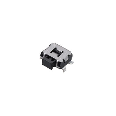
3.5 mm×2.9 mm Side-operational SMD
Light Touch Switches
Type:
EVQP7/EVQP3/EVQ9P7
■ Features
● External dimensions : 3.5 mm×2.9 mm, Height 1.35 mm
● A wide range of terminal type : L-shape, J-bent, Straight
● High mount ability
● Push plate strength enhanced type
■ Recommended Applications
● Operation switches for portable electronic equipment
(Mobile phones, Digital still cameras, Camcorders,
Portable audio players, etc.)
■ Explanation of Part Numbers
1
2
3
4
P
Product Code
9
5
6
7
8
9
73
P
Type・Operating Force
Product Height
■ Specifications
Type
Snap action / Push-on type SPST
Rating
10 μA 2 V DC to 50 mA 12 V DC (Resistive load)
Contact Resistance
500 mΩ max.
Insulation Resistance
Electrical
100 MΩ min. (at 100 V DC)
Dielectric Withstanding Voltage
250 V AC for 1 minute
Bouncing
10 ms max. (ON, OFF)
Operating Force
Mechanical
1.6 N, 2.2 N
Push Travel
Endurance
0.2 mm
Push Strength
30 N (1 minute)
Operating Life
100,000 cycles min.
Operating Temperature
–20 °C to +70 °C
–40 °C to +85 °C (Bulk)
–20 °C to +60 °C (Taping)
Storage Temperature
Minimum Quantity/Packing Unit
5,000 pcs. Embossed Taping (Reel Pack)
Quantity/Carton
25,000 pcs.
Design and specifications are each subject to change without notice. Ask factory for the current technical specifications before purchase and/or use.
Should a safety concern arise regarding this product, please be sure to contact us immediately.
�������
LQGXVWULDO�SDQDVRQLF�FRP�DF�H�
1
© Panasonic Corporation 2019
ANCTB21E 201903-Fd
�Light Touch Switches/EVQP7/P3/9P7
■ Dimensions in mm (not to scale)
No. 1
General dimension tolerance : ± 0.2
( )dimensions are reference dimensions.
4.7
3.5
EVQP7A
EVQP7J
,
With straight terminals
Without boss
1
2
,
2
Knob
0.5±0.1
0.62±0.1
1.48±0.1
(Embossed Taping)
3.55
2.9
1.6
1
1.7
R0.2
1.1±0.1
,
1
1.35
1
,
2
2
Circuit diagram
A
B
2.5±0.1
5.0±0.1
2.2±0.1
C
0.4±0.1
(2.8)
Either A or B or C type
will be used because of
variwty of molding dies.
PWB land pattern for reference
Part Numbers
Operating Force
Height
Push Plate Color
Operating Life
EVQP7A01P
2.2 N
1.35 mm
Black
100,000 cycles
EVQP7J01P
1.6 N
1.35 mm
Black
100,000 cycles
No. 2
EVQP7C
EVQP7L
,
2
1.7
0.5
1.35
Knob
R0.2
1.1±0.1
2
0.5±0.1
0.62±0.1
1.48±0.1
With straight terminals
With boss
,
1
1
3.55
2.9
1.6
(Embossed Taping)
General dimension tolerance : ± 0.2
( )dimensions are reference dimensions.
4.7
3.5
,
1
1
2
2
,
0.2
Circuit diagram
A
5.0±0.1
2.2±0.1
B
.2
φ0
0.4±0.1
1.8±0.1
2.5±0.1
.1
1.8±0.05
φ0.6 +0
5 -0
(2.8)
Either A or B type
will be used because of
variwty of molding dies.
.2
+0
-0
0.7
2-φ
PWB land pattern for reference
Part Numbers
Operating Force
Height
Push Plate Color
Operating Life
EVQP7C01P
2.2 N
1.35 mm
Black
100,000 cycles
EVQP7L01P
1.6 N
1.35 mm
Black
100,000 cycles
Design and specifications are each subject to change without notice. Ask factory for the current technical specifications before purchase and/or use.
Should a safety concern arise regarding this product, please be sure to contact us immediately.
Panasonic Corporation Electromechanical Control Business Division
industrial.panasonic.com/ac/e/
2
© Panasonic Corporation 2019
ANCTB21E 201903-Fd
�Light Touch Switches/EVQP7/P3/9P7
■ Dimensions in mm (not to scale)
No. 3
General dimension tolerance : ± 0.2
( )dimensions are reference dimensions.
3.5
EVQP7B
EVQP7K
,
2
2
Knob
0.5±0.1
0.62±0.1
1.48±0.1
With J-bent terminals
Without boss
3.55
2.9
1.6
(Embossed Taping)
,
1
1
1.7
R0.2
1.1±0.1
,
1
1.35
0.6
1
,
2
0
4.3 –0.2
2
Circuit diagram
B
C
5.0±0.1
2.2±0.1
2.5±0.1
A
0.4±0.1
(2.8)
Either A or B or C type
will be used because of
variwty of molding dies.
PWB land pattern for reference
Part Numbers
Operating Force
Height
Push Plate Color
Operating Life
EVQP7B01P
2.2 N
1.35 mm
Black
100,000 cycles
EVQP7K01P
1.6 N
1.35 mm
Black
100,000 cycles
No. 4
General dimension tolerance : ± 0.2
( )dimensions are reference dimensions.
3.5
EVQP7D
EVQP7M
2
,
2
1.7
R0.2
1.1±0.1
,
1
1
2
2
4.3 +0
-0.2
φ0.65 +0
–0
0.2
1.35
0.5 0.6
Knob
0.5±0.1
0.62±0.1
1.48±0.1
With J-bent terminals
With boss
3.55
2.9
1.6
(Embossed Taping)
,
1
1
,
Circuit diagram
A
5.0±0.1
2.2±0.1
B
.2
φ0
0.4±0.1
1.8±0.1
2.5±0.1
1.8±0.05
.1
(2.8)
Either A or B type will be used because of
variwty of molding dies.
.2
+00
–
0.7
2-φ
PWB land pattern for reference
Part Numbers
Operating Force
Height
Push Plate Color
Operating Life
EVQP7D01P
2.2 N
1.35 mm
Black
100,000 cycles
EVQP7M01P
1.6 N
1.35 mm
Black
100,000 cycles
Design and specifications are each subject to change without notice. Ask factory for the current technical specifications before purchase and/or use.
Should a safety concern arise regarding this product, please be sure to contact us immediately.
Panasonic Corporation Electromechanical Control Business Division
industrial.panasonic.com/ac/e/
3
© Panasonic Corporation 2019
ANCTB21E 201903-Fd
�Light Touch Switches/EVQP7/P3/9P7
■ Dimensions in mm (not to scale)
0.5±0.1
0.62±0.1
1.48±0.1
No. 5
EVQP3
EVQ9P
0.1 max.
3.55
2.9
1.6
’
With L-shape terminals
Without boss
’
Knob
R0.2
0.6
1.1±0.1
1.7
1.35
’
’
3.9
B
Through Hole
5.5±0.1
4.05±0.1
2.2±0.1
C
(2.8)
Either A or B or C type
will be used because of
variwty of molding dies.
0.8±0.1
2.5±0.1
0.4±0.1
A
φ0
.6 +0.
Circuit diagram
–0 1
(Embossed Taping)
General dimension tolerance : ± 0.2
( )dimensions are reference dimensions.
0.5±0.1
0.62±0.1
4.7
3.5
PWB land pattern for reference
Part Numbers
Operating Force
Height
Push Plate Color
Operating Life
EVQP3401P
2.2 N
1.35 mm
Black
100,000 cycles
EVQ9P701P
1.6 N
1.35 mm
Black
100,000 cycles
■ Recommended Reflow Soldering Conditions
Operation Top (°C)
MAX.
260
Fan or Normal Temp.
230
180
150
(Normal Temp.)
90±30
40±10
Soldering Time (s)
● Embossed Carrier Taping
Tape width=12.0 mm
t1
Feeding hole
Chip pocket
P2 P0
Taping condition : Lack of products in the middle of taping should be
one MAX, but total quantity specified in the
specifications should be secured.
Peeling off strength of top tape : It should be within 0.2N to 1.0N at
165 degree in peeling off angle.
Joint of carrier tape : One joint per one reel may exist.
E
φD0
B
F
W
A
t2
P1
Chip component
Tape running direction
● Straight terminals, L-shape terminals type
Part No.
EVQP7, EVQP3
EVQ9P7
Height
A
Unit: mm
B
W
F
E
P1
P2
P0
1.35
5.2±0.2
4.5±0.2
12.0±0.3
5.5±0.1
1.75±0.10
8.0±0.1
2.0±0.1
4.0±0.1
Height
A
B
W
F
E
P1
P2
P0
D0 Dia.
+0.1
–0
1.5
t1
t2
0.3±0.1
1.5±0.2
● J-bent type
Part No.
EVQP7, EVQP3
Unit: mm
1.35
4.5±0.2
4.5±0.2
12.0±0.3
5.5±0.1
1.75±0.10
8.0±0.1
2.0±0.1
D0 Dia.
4.0±0.1
+0.1
–0
1.5
t1
t2
0.3±0.1
1.5±0.2
Design and specifications are each subject to change without notice. Ask factory for the current technical specifications before purchase and/or use.
Should a safety concern arise regarding this product, please be sure to contact us immediately.
Panasonic Corporation Electromechanical Control Business Division
industrial.panasonic.com/ac/e/
4
© Panasonic Corporation 2019
ANCTB21E 201903-Fd
�Requests to customers
Please refer to "the latest product specifications" when designing your product.
Requests to customers :
https://industrial.panasonic.com/ac/e/salespolicies/
Safety Precautions
When using our products, no matter what sort of equipment they might be used for, be sure to
confirm the applications and environmental conditions with our specifications in advance.
Please contact ..........
Electromechanical Control Business Division
1006, Oaza Kadoma, Kadoma-shi, Osaka 571-8506, Japan
industrial.panasonic.com/ac/e/
©Panasonic Corporation 2019
ANCTB21E-1 201903-Fd
Specifications are subject to change without notice.
�