891
FIBER
SENSORS
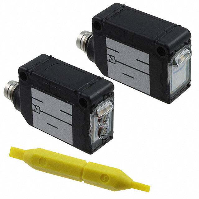
Water Detection Sensor
EZ-10 SERIES
Related Information
■■General terms and conditions...............F-3
■■Glossary of terms.........................P.1549~
■■Selection guide.............................. P.865~
■■General precautions......................P.1552~
LASER
SENSORS
PHOTOELECTRIC
SENSORS
Recognition
(Excluding 5 m cable length type)
MICRO
PHOTOELECTRIC
SENSORS
AREA
SENSORS
SAFETY LIGHT
CURTAINS /
SAFETY COMPONENTS
PRESSURE /
FLOW
SENSORS
INDUCTIVE
PROXIMITY
SENSORS
PARTICULAR
USE SENSORS
SENSOR
OPTIONS
SIMPLE
WIRE-SAVING
UNITS
WIRE-SAVING
SYSTEMS
MEASUREMENT
SENSORS
panasonic.net/id/pidsx/global
STATIC
CONTROL
DEVICES
LASER
MARKERS
PLC
HUMAN MACHINE
INTERFACES
ENERGY
MANAGEMENT
SOLUTIONS
FA COMPONENTS
MACHINE VISION
SYSTEMS
Detects water...reliably!
Strong penetration power
Not affected by drops, bubbles or froth
As the penetration power is strong, its beam can pass
through not only translucent containers (PFA tanks, etc.)
but also opaque containers of shampoo bottles, etc., and
can reliably detect the liquid inside.
It is possible to set its sensitivity adjuster so that water
drops, bubbles in the water, or froth on the water surface
are not detected.
Penetration in case of an empty container (Typical)
Water drops
Bubbles
100
UV CURING
SYSTEMS
EZ-10
Froth
10
Shampoo bottle
Opaque container
0
Colored bottle
2
Milk-white container
Ultrasonic
Small / Slim
Object Detection
Obstacle
Detection
20
Transparent container
Selection
Guide
Liquid Leak
Detection
Liquid Level
Detection
Water
Detection
Color Mark
Detection
Wafer
Detection
Penetration (%)
40
* The graph above is merely a guideline. Penetration
power changes due to container material, thickness
and color. We strongly recommend that you conduct
verification tests prior to use.
IP67 protection
The sensor can be hosed down because of its IP67
construction and the non-corrosive stainless steel sensor
mounting bracket.
Note: However, take care that if it is exposed to water splashes during
operation, it will detect the splashed water itself.
Adjacent sensor mounting possible
Plug-in connector type is available
Several sensors can be mounted adjacently by fitting
optional slit masks. Further, they can detect the liquid
level accurately.
Plug-in connector type which enables connection /
disconnection of the cable by one-touch is available.
Anyone can easily replace the sensor in a minute.
�Water Detection Sensor
EZ-10 SERIES
APPLICATIONS
FIBER
SENSORS
Detecting level of aqueous solution in resin tank
It can reliably detect a liquid even
in an opaque container.
Packing
892
Pipe
Detecting the boundary between water and oil
Since it does not detect oil, it can
reliably detect the boundary
between water and oil.
EZ-11
Detecting presence of liquid in colored bottle
Aqueous liquids in translucent
colored bottles can be reliably
detected.
Separator
LASER
SENSORS
PHOTOELECTRIC
SENSORS
MICRO
PHOTOELECTRIC
SENSORS
AREA
SENSORS
EZ-11
Oil
EZ-11
Aqueous solution
Water
SAFETY LIGHT
CURTAINS /
SAFETY
COMPONENTS
PRESSURE /
FLOW
SENSORS
INDUCTIVE
PROXIMITY
SENSORS
PARTICULAR
USE
SENSORS
ORDER GUIDE
Type
SENSOR
OPTIONS
Appearance
Sensing range (Note 1)
NPN
output
5m
16.404 ft
PNP
output
without container
or pipe
Model No.
(Note 2)
Output
EZ-11
NPN open-collector
transistor
EZ-11-PN
PNP open-collector
transistor
NOTE: Mounting bracket is not supplied with the sensor. Please select from the range of optional sensor mounting
brackets (five types).
Notes: �1) The sensing range shortens depending on the thickness, material, color, etc., of the container or pipe.
2) Models whose model name on the product nameplate is followed by “P” are emitters, while those whose model name is followed by “D” are receivers.
SIMPLE
WIRE-SAVING
UNITS
WIRE-SAVING
SYSTEMS
MEASUREMENT
SENSORS
STATIC
CONTROL
DEVICES
LASER
MARKERS
PLC
HUMAN
MACHINE
INTERFACES
ENERGY
MANAGEMENT
SOLUTIONS
5 m 16.404 ft cable length type and plug-in connector type
5 m 16.404 ft cable length type (standard: 2 m 6.562 ft) and plug-in connector type (standard: cable type) are also available.
(5 m 16.404 ft cable length type is not available for the EZ-11-PN.)
When ordering this type, suffix “-C5” for 5 m 16.404 ft cable length type, “-J” for plug-in connector type to the model No.
Please order the suitable mating cable separately for plug-in connector type.
(e.g.) Plug-in connector type of EZ-11-PN is “EZ-11-PN-J”.
FA
COMPONENTS
MACHINE
VISION
SYSTEMS
UV
CURING
SYSTEMS
• Mating cable for plug-in connector type (2 cables are required)
Type
Straight
Elbow
Model No.
Description
CN-24E-C2
Length: 2 m 6.562 ft
CN-24E-C5
Length: 5 m 16.404 ft
CN-24EL-C2
Length: 2 m 6.562 ft
CN-24EL-C5
Length: 5 m 16.404 ft
0.2 mm 4-core cabtyre
cable with connector on
one end
Cable outer diameter:
ø3.7 mm ø0.146 in
• CN-24E-C2□, CN-24E-C5
Selection
Guide
Liquid Leak
Detection
2
ø9mm
ø0.354 in
Liquid Level
Detection
Water
Detection
30.7mm
1.209 in
Color Mark
Detection
Wafer
Detection
ø3.7mm
ø0.146 in
Ultrasonic
Small / Slim
Object Detection
Obstacle
Detection
• CN-24EL-C2□, CN-24EL-C5
EZ-10
23mm
0.906 in ø9mm
ø0.354 in
23.7mm
0.933 in
ø3.7mm
ø0.146 in
�893
FIBER
SENSORS
Water Detection Sensor
EZ-10 SERIES
OPTIONS
LASER
SENSORS
PHOTOELECTRIC
SENSORS
Designation
Model No.
OS-CX-05
MICRO
PHOTOELECTRIC
SENSORS
AREA
SENSORS
Round slit mask
SAFETY LIGHT
CURTAINS /
SAFETY
COMPONENTS
PARTICULAR
USE
SENSORS
Sensor mounting
bracket (Note 1)
PLC
UV
CURING
SYSTEMS
• Sensing range: 400 mm 15.748 in
Slit on both sides
• Sensing range: 60 mm 2.362 in
Slit on one side
• Sensing range: 1 m 3.281 ft
Slit on both sides
• Sensing range: 250 mm 9.843 in
Slit on one side
• Sensing range: 800 mm 31.496 in
Slit on both sides
• Sensing range: 250 mm 9.843 in
Slit on one side
• Sensing range: 1.3 m 4.265 ft
Slit on both sides
• Sensing range: 600 mm 23.622 in
OS-CX-2×6
Slit on one side
• Sensing range: 2 m 6.562 ft
Slit on both sides
• Sensing range: 1.3 m 4.265 ft
MS-CX2-1
Foot angled mounting bracket
(Two brackets are required.)
MS-CX2-2
Foot biangled mounting bracket
(Two brackets are required.)
MS-CX2-4
Protective mounting bracket
(Two brackets are required.)
MS-CX2-5
Back biangled mounting bracket
(Two brackets are required.)
MS-CX-3
Back angled mounting bracket
(Two brackets are required.)
MS-AJ1
Horizontal mounting type
MS-AJ2
Vertical mounting type
MS-AJ1-A
Horizontal mounting type
MS-AJ2-A
Vertical mounting type
Slit size 2 × 6 mm
0.079 × 0.236 in
LASER
MARKERS
MACHINE
VISION
SYSTEMS
Slit on one side
Slit size ø1 mm
ø0.039 in
Slit size 1 × 6 mm
0.039 × 0.236 in
MEASUREMENT
SENSORS
FA
COMPONENTS
• Sensing range: 10 mm 0.394 in
OS-CX-1×6
Rectangular
slit mask
WIRE-SAVING
SYSTEMS
ENERGY
MANAGEMENT
SOLUTIONS
Slit on both sides
OS-CX-1
Slit size 0.5 × 6 mm
0.020 × 0.236 in
SIMPLE
WIRE-SAVING
UNITS
HUMAN
MACHINE
INTERFACES
• Sensing range: 200 mm 7.874 in
OS-CX-05×6
SENSOR
OPTIONS
STATIC
CONTROL
DEVICES
Slit on one side
Slit size ø2 mm
ø0.079 in
INDUCTIVE
PROXIMITY
SENSORS
Universal
sensor
mounting stand
(Note 2)
Liquid Leak
Detection
Liquid Level
Detection
Water
Detection
Swivel:
360° rotation
45°
45°
Elevation
angle: ±45°
Height
adjustment:
150 mm
5.906 in
approx.
With the lateral
arm, the sensor
can sense
from above a
production line.
Basic assembly
Lateral arm assembly
Rectangular slit mask
(Stainless steel)
Used for narrowing
the beam for cases
when detecting water
or other substances
inside slender pipes.
Fitted on the front
face of the sensor
with one-touch.
Two M3 (length 12 mm 0.472 in)
screws with washers are attached.
• MS-CX2-4
Two M3 (length 14 mm 0.551 in)
screws with washers are attached.
Forward / back
adjustment:
130mm
5.118 in
approx.
360°
rotation
Mounting hole
for M6 screw
45°
• MS-AJ2
45°
Elevation
angle: ±45°
Height
adjustment:
150 mm
5.906 in
approx.
Mounting hole
for M6 screw
With the lateral
arm, the sensor
can sense
from above a
production line.
Forward / back
adjustment:
130mm
5.118 in
approx.
360°
rotation
Mounting hole
for M6 screw
Swivel:
360° rotation
Height
adjustment:
150 mm
5.906 in
approx.
45°
45°
Angle
adjustment: ±45°
• MS-CX-3
Height
adjustment:
150 mm
5.906 in
approx.
• MS-AJ2-A
Swivel:
360° rotation
45°
Swivel:
360° rotation
45°
Angle
adjustment: ±45°
Ultrasonic
EZ-10
• OS-CX-□×6
• MS-CX2-1
• MS-AJ1-A
Wafer
Detection
Obstacle
Detection
Rectangular slit mask
Sensor mounting bracket
Universal sensor mounting stand
Color Mark
Detection
Small / Slim
Object Detection
Used for narrowing
the beam for cases
when detecting water
or other substances
inside slender pipes.
Fitted on the front
face of the sensor
with one-touch.
Round slit mask
(Stainless steel)
• MS-CX2-2
Two M3 (length 12 mm 0.472 in)
screws with washers are attached.
• MS-CX2-5
Notes: 1) �The plug-in connector type sensor does not allow use of some sensor mounting brackets
because of the protrusion of the connector.
2) Refer to p.953~ for the universal sensor mounting stand.
• MS-AJ1
Selection
Guide
• OS-CX-□
Slit size ø0.5 mm
ø0.020 in
OS-CX-2
PRESSURE /
FLOW
SENSORS
Round slit mask
Description
Mounting hole
for M6 screw
Two M3 (length 12 mm 0.472 in)
screws with washers are attached.
Two M3 (length 12 mm 0.472 in)
screws with washers are attached.
�Water Detection Sensor
EZ-10 SERIES
SPECIFICATIONS
Type
Item
Model No.
CE marking directive compliance
894
FIBER
SENSORS
NPN output
PNP output
EZ-11
EZ-11-PN
EMC Directive, RoHS Directive
LASER
SENSORS
PHOTOELECTRIC
SENSORS
MICRO
PHOTOELECTRIC
SENSORS
Sensing range
5 m 16.404 ft (without container or pipe)(Note 2)
Sensing object
ø12 mm ø0.472 in or more liquid which contains water, or opaque object (Note 3)
AREA
SENSORS
Supply voltage
12 to 24 V DC ±10 % Ripple P-P 10 % or less
SAFETY LIGHT
CURTAINS /
SAFETY
COMPONENTS
Current consumption
Output
Utilization category
Output operation
Short-circuit protection
Response time
Operation indicator
Stability indicator
Power indicator
Sensitivity adjuster
Environmental resistance
Pollution degree
Protection
Ambient temperature
Ambient humidity
Ambient illuminance
Voltage withstandability
Emitter: 25 mA or less, Receiver: 25 mA or less
NPN open-collector transistor
• Maximum sink current: 100 mA
• Applied voltage : 30 V DC or less (between output and 0 V)
• Residual voltage: 1.5 V or less (at 100 mA sink current)
0.4 V or less (at 16 mA sink current)
PNP open-collector transistor
• Maximum source current: 100 mA
• Applied voltage: 30 V DC or less (between output and V)
• Residual voltage: 1.5 V or less (at 100 mA source current)
0.4 V or less (at 16 mA source current)
DC-12 or DC-13
Switchable either Light-ON or Dark-ON
Incorporated
12 ms or less
Orange LED (lights up when the output is ON), located on the receiver
Green LED (lights up under stable light received condition or stable dark condition), located on the receiver
Orange LED (lights up when the power is ON), located on the emitter
Continuously variable adjuster
3 (Industrial environment)
IP67 (IEC)
0 to +55 °C +32 to +131 °F (No dew condensation or icing allowed), Storage:–30 to +70 °C –22 to +158 °F
35 to 85 % RH, Storage: 35 to 85 % RH
Incandescent light: 3,000 ℓx or less at the light-receiving face
1,000 V AC for one min. between all supply terminals connected together and enclosure
Insulation resistance
20 MΩ, or more, with 250 V DC megger between all supply terminals connected together and enclosure
Vibration resistance
10 to 500 Hz frequency, 3 mm 0.118 in double amplitude (20 G max.) in X, Y and Z directions for two hours each
Shock resistance
Emitting element
Material
Cable
Cable extension
Weight
Accessory
500 m/s2 acceleration (50 G approx.) in X, Y and Z directions three times each
Infrared LED (modulated)
Polycarbonate
PRESSURE /
FLOW
SENSORS
INDUCTIVE
PROXIMITY
SENSORS
PARTICULAR
USE
SENSORS
SENSOR
OPTIONS
SIMPLE
WIRE-SAVING
UNITS
WIRE-SAVING
SYSTEMS
MEASUREMENT
SENSORS
STATIC
CONTROL
DEVICES
LASER
MARKERS
PLC
HUMAN
MACHINE
INTERFACES
ENERGY
MANAGEMENT
SOLUTIONS
FA
COMPONENTS
MACHINE
VISION
SYSTEMS
UV
CURING
SYSTEMS
0.2 mm2 3-core (emitter: 2-core) oil resistant cabtyre cable, 2 m, 6.562 ft long
Extension up to total 100 m 328.084 ft is possible, for both emitter and receiver, with 0.3 mm2, or more, cable.
Emitter: 45 g approx., Receiver: 50 g approx.
Adjusting screwdriver: 1 pc.
Notes: �1) Where measurement conditions have not been specified precisely, the conditions used were an ambient temperature of +23 °C +73.4 °F.
2) The sensing range shortens depending on the thickness, material, color, etc., of the container or pipe.
3) If there are two slit on both sides, the size of those slit represents the min. sensing object.
Selection
Guide
Liquid Leak
Detection
Liquid Level
Detection
Water
Detection
Color Mark
Detection
Wafer
Detection
Ultrasonic
Small / Slim
Object Detection
Obstacle
Detection
EZ-10
�895
Water Detection Sensor
I/O CIRCUIT DIAGRAMS
FIBER
SENSORS
LASER
SENSORS
PHOTOELECTRIC
SENSORS
NPN output type
I/O circuit diagram
MICRO
PHOTOELECTRIC
SENSORS
SAFETY LIGHT
CURTAINS /
SAFETY
COMPONENTS
PRESSURE /
FLOW
SENSORS
D
INDUCTIVE
PROXIMITY
SENSORS
SIMPLE
WIRE-SAVING
UNITS
WIRE-SAVING
SYSTEMS
MEASUREMENT
SENSORS
STATIC
CONTROL
DEVICES
LASER
MARKERS
(Brown / 1) + V
Brown
(Black / 4)
Output (Note 1)
Tr
ZD
FA
COMPONENTS
MACHINE
VISION
SYSTEMS
UV
CURING
SYSTEMS
Selection
Guide
Liquid Leak
Detection
Liquid Level
Detection
Water
Detection
Color Mark
Detection
Wafer
Detection
Ultrasonic
Small / Slim
Object Detection
Obstacle
Detection
EZ-10
-
12 to 24V DC
±10%
Black (Note 1)
Load
+
-
12 to 24V DC
±10%
Blue
Note: The emitter does not incorporate the black wire.
Users’ circuit
Connector pin position (plug-in connector type)
Notes: 1) The emitter does not incorporate the output.
2) When the mating cable is connected to the plug-in connector type
sensor, the white wire of the mating cable is not connected.
2
Not connected
(Note 2)
1
V
Symbols ... D : Reverse supply polarity protection diode
ZD: Surge absorption zener diode
Tr : NPN output transistor
4
Output (Note 1)
3
0V
Notes: 1) The emitter does not incorporate the output.
2) When the mating cable is connected to the plug-in connector type
sensor, the white wire of the mating cable is not connected.
PNP output type
I/O circuit diagram
Wiring diagram
Color code / Connector pin No.
of the plug-in connector type
(Brown / 1) + V
Sensor circuit
ENERGY
MANAGEMENT
SOLUTIONS
+
(Blue / 3) 0 V
PLC
HUMAN
MACHINE
INTERFACES
Load
100 mA max.
Internal circuit
PARTICULAR
USE
SENSORS
SENSOR
OPTIONS
Wiring diagram
Color code / Connector pin No.
of the plug-in connector type
Sensor circuit
AREA
SENSORS
EZ-10 SERIES
ZD
Tr
100mA max.
(Black / 4)
Output (Note 1)
D
Internal circuit
Brown
+
-
12 to 24V DC
±10%
(Blue / 3) 0 V
Users’ circuit
Notes: 1) The emitter does not incorporate the output.
2) When the mating cable is connected to the plug-in
connector type sensor, the white wire of the mating cable is not
connected.
Symbols ... D : Reverse supply polarity protection diode
ZD: Surge absorption zener diode
Tr : PNP output transistor
+
Black (Note)
Load
Blue
Load
-
12 to 24 V DC
±10 %
Note: The emitter does not incorporate the black wire.
Connector pin position (plug-in connector type)
2
Not connected
(Note 2)
1
V
4
Output (Note 1)
3
0V
Notes: 1) The emitter does not incorporate the output.
2) When the mating cable is connected to the plug-in connector type
sensor, the white wire of the mating cable is not connected.
�Water Detection Sensor
EZ-10 SERIES
896
SENSING CHARACTERISTICS (TYPICAL)
Emitter
ℓ
2
6.562
L
Receiver
Slit on one
side
1
3.281
Slit on both
sides
0.5
1.640
Horizontal
& vertical
directions
Emitter
ℓ
L
Receiver
0
100
50
0
50
100
3.937
1.969
1.969
3.937
(Down) Left
Center
Right (Up)
Operating point ℓ (mm in)
Receiver
50
0
50
Parallel deviation with rectangular
slit masks (0.5 × 6 mm 0.020 × 0.236 in)
1
3.281
1.5
4.921
Slit on
both
sides
Emitter
0.5
1.640
ℓ
Horizontal
& vertical
directions
L
Receiver
0
100
50
0
50
100
3.937
1.969
1.969
3.937
(Down) Left
Center
Right (Up)
Operating point ℓ (mm in)
Slit on one
side
Emitter
Slit on both
sides
L
Slit on both
sides
Emitter
ℓ
L
1
3.281
Emitter
0.5
ℓ L
1.640 Horizontal
& vertical
directions
Receiver
0
100
50
0
50
100
3.937
1.969
1.969
3.937
(Down) Left
Center
Right (Up)
Operating point ℓ (mm in)
2
6.562
Emitter
1
3.281
ℓ
Horizontal
& vertical
directions
L
• The stability indicator (green) lights up when the incident
light intensity has sufficient margin with respect to the
operation level. If the incident light intensity level is such
that the stability indicator lights up, stable sensing can
be done without the light received operation and the
light interrupted operation being affected by a change in
ambient temperature or supply voltage.
• The tightening torque should be 0.5 N·m or less.
• When connecting the mating cable to the plug-in
connector type sensor, the tightening torque should be
0.4 N·m or less.
STATIC
CONTROL
DEVICES
HUMAN
MACHINE
INTERFACES
ENERGY
MANAGEMENT
SOLUTIONS
FA
COMPONENTS
MACHINE
VISION
SYSTEMS
UV
CURING
SYSTEMS
Liquid Level
Detection
Light received operation
Water
Detection
100
operation
0
Setting distance
Wiring
MEASUREMENT
SENSORS
Liquid Leak
Detection
Light interrupted
Lights up
15% approx.
Lights off
15% approx.
Lights up
Output
operation
level
Light
interruption
margin
SENSOR
OPTIONS
Selection
Guide
Output operation
Sensor
mounting
bracket
MS-CX2-1
(Optional)
PARTICULAR
USE
SENSORS
LASER
Operation of stability indicator
M3
(length 12 mm 0.472 in)
screw with washers
INDUCTIVE
PROXIMITY
SENSORS
MARKERS
Receiver
0
200
100
0
100
200
7.874
3.937
3.937
7.874 PLC
(Down) Left
Center
Right (Up)
Operating point ℓ (mm in)
Stability indicator
Incident
light
margin
PRESSURE /
FLOW
SENSORS
WIRE-SAVING
SYSTEMS
Slit on
both
sides
Refer to p.1552~ for general precautions.
Mounting
SAFETY LIGHT
CURTAINS /
SAFETY
COMPONENTS
SIMPLE
WIRE-SAVING
UNITS
Slit on one
side
Slit on both
sides
PHOTOELECTRIC
SENSORS
AREA
SENSORS
Receiver
0
40
20
0
20
40
0.787
1.575
1.575 0.787
(Down) Left
Center
Right (Up)
Operating point ℓ (mm in)
Slit on one
side
PRECAUTIONS FOR PROPER USE
• Never use this product as a sensing device
for personnel protection.
• In case of using sensing devices for
personnel protection, use products which
meet laws and standards, such as OSHA,
ANSI or IEC etc., for personnel protection
applicable in each region or country.
ℓ
Slit on one
side
200
7.874
LASER
SENSORS
MICRO
PHOTOELECTRIC
SENSORS
Parallel deviation with rectangular
Parallel deviation with rectangular
slit masks (1 × 6 mm 0.039 × 0.236 in) slit masks (2 × 6 mm 0.079 × 0.236 in)
2
6.562
Slit on one
side
400
15.748
Receiver
0
20
10
0
10
20
0.787 0.394
0.394
0.787
(Down) Left
Center
Right (Up)
Operating point ℓ (mm in)
100
(Down) Left
Center
Right (Up)
Operating angle θ( ° )
Setting distance L (mm ft)
Setting distance L (mm ft)
Parallel deviation with round
slit masks (ø2 mm ø0.079 in)
100
3.937
θ L
2
6.562
0
100
0
200
100
0
100
200
7.874
3.937
3.937
7.874
(Down) Left
Center
Right (Up)
Operating point ℓ (mm in)
Emitter
Receiver
angular
deviation
4
13.123
Horizontal
& vertical
directions
Incident light intensity (%)
4
13.123
200
7.874
Emitter
angular
deviation
Horizontal
& vertical
directions
Parallel deviation with round
slit masks (ø1 mm ø0.039 in)
Setting distance L (mm in)
Setting distance L (mm ft)
Setting distance L (mm ft)
6
19.685
Horizontal &
vertical directions
6
19.685
Horizontal &
vertical
directions
Setting distance L (mm in)
8
26.247
8
26.247
Parallel deviation with round
slit masks (ø0.5 mm ø0.020 in)
Setting distance L (mm ft)
Angular deviation
Setting distance L (mm ft)
Parallel deviation
FIBER
SENSORS
0
Others
• Because these units use special emitter and receiver
elements, they are susceptible to the effects of operating
ambient temperature and humidity. Sensitivity adjustment
should be performed in the environment in which they will
actually be used.
• Do not use during the initial transient time (100 ms) after
the power supply is switched on.
Color Mark
Detection
Wafer
Detection
Ultrasonic
Small / Slim
Object Detection
Obstacle
Detection
EZ-10
�897
FIBER
SENSORS
LASER
SENSORS
Water Detection Sensor
EZ-11 EZ-11-PN
SAFETY LIGHT
CURTAINS /
SAFETY
COMPONENTS
2-M3 × 0.5 0.020
thru-hole threads
12
0.472
1.7
0.067
PRESSURE /
FLOW
SENSORS
SIMPLE
WIRE-SAVING
UNITS
ø11
ø0.433
MS-CX2-1
5
0.197
3.4
0.134
14
0.551 8
0.315
12
0.472
R12
R0.472
ENERGY
MANAGEMENT
SOLUTIONS
3.4
25 0.134
42.5 0.984
1.673
FA
COMPONENTS
t 1.2
t 0.047
Assembly dimensions
Mounting drawing with the
receiver of EZ-11(-PN)
3
0.118
R25
R0.984
3.4
0.134
3.4
0.134
2-ø3.4 ø0.134 holes
10
0.394
42.5
1.673
t 1.2
t 0.047
Assembly dimensions
14
0.551
7.8 0.307
Color Mark
Detection
15.8
0.622
14
0.551
Small / Slim
Object Detection
EZ-10
7°
Sensor mounting bracket (Optional)
Water
Detection
36
1.417
3
0.118
5
0.197
22
0.866
12.5
0.492
MS-CX2-2
Liquid Level
Detection
Obstacle
Detection
12
0.472
25
0.984
31
1.220
25
0.984
9.5
0.374
Two M3 (length 12 mm 0.472 in) screws
with washers are attached.
Ultrasonic
R12
R0.472
Beam axis
20
0.787
12.5
0.492
0.5
0.020
12
0.472
Material: Stainless steel (SUS304)
Wafer
Detection
3.4 14
26
0.1340.551
1.024
14°
14°
22
0.866
15 0.591
7°
HUMAN
MACHINE
INTERFACES
Selection
Guide
M8 connector
16
0.630
Sensor mounting bracket (Optional)
PLC
Liquid Leak
Detection
2-M3 × 0.5 0.020
thru-hole threads
Notes: 1
� ) Not incorporated on the emitter.
2) It is the power indicator (orange) on the emitter.
LASER
MARKERS
UV
CURING
SYSTEMS
3
0.118
Notes: �1) Not incorporated on the emitter.
2) It is the power indicator (orange) on the emitter.
STATIC
CONTROL
DEVICES
MACHINE
VISION
SYSTEMS
Sensitivity adjuster (Note 1)
22
0.866
3
0.118
15.5
0.610
34.5 31
40.5 1.358 1.220
25
1.594
0.984
Beam
axis
WIRE-SAVING
SYSTEMS
MEASUREMENT
SENSORS
1.7
0.067
12
0.472
ø3.7 ø0.146 cable, 2 m 6.562 ft long
Operation mode switch (Note 1)
Operation indicator (Orange)(Note 2)
20
0.787
3
0.118
3
0.118
Sensor
Stability indicator (Green)(Note 1)
Sensitivity adjuster (Note 1)
15.5
0.610
31
25
1.220
0.984
Beam
axis
EZ-11-J EZ-11-PN-J
Operation mode switch (Note 1)
Operation indicator (Orange)(Note 2)
AREA
SENSORS
SENSOR
OPTIONS
Sensor
Stability indicator (Green)(Note 1)
MICRO
PHOTOELECTRIC
SENSORS
PARTICULAR
USE
SENSORS
Refer to p.955~ for dimensions of the universal sensor mounting stand.
The CAD data can be downloaded from our website.
DIMENSIONS (Unit: mm in)
PHOTOELECTRIC
SENSORS
INDUCTIVE
PROXIMITY
SENSORS
EZ-10 SERIES
22
0.866
7 0.276
8-ø3.4 ø0.134 holes
Mounting drawing with the
receiver of EZ-11(-PN)
7.8
0.307
15.8
0.622
22
0.866
14
0.551
(3.6)
(0.142)
Beam axis
10
25
0.394 0.984
55
2.165
25
0.984
36
55 1.417
2.165
28
1.102
4.5 23
0.177 0.906 15.5
0.610
R0.472
R12
14°
t2
t 0.079
4.5
0.177
Material: Stainless steel (SUS304)
Two M3 (length 12 mm 0.472 in) screws
with washers are attached.
12
0.472
5
0.197
4
0.157
7
0.276
14°
t2
t 0.079
4.5
0.177
4
0.157
7.8 0.307
4.5
0.177
4.5
0.177
4.5
R12
0.177 15.5
R0.472
0.610
7 0.276
12
0.472
5 0.197
7.8
0.307
�Water Detection Sensor
EZ-10 SERIES
898
Refer to p.955~ for dimensions of the universal sensor mounting stand.
The CAD data can be downloaded from our website.
DIMENSIONS (Unit: mm in)
MS-CX2-4
Sensor mounting bracket (Optional)
Mounting drawing with the
receiver of EZ-11(-PN)
7
0.276
19
0.748
5.5
0.217
SENSOR
25
0.984
46 1.811
7º
4 0.157
INDUCTIVE
PROXIMITY
SENSORS
0.5
0.020
19
0.748
R9.5
R0.374
PRESSURE /
FLOW
SENSORS
29
1.142
6.2
0. 244
3.4
0.134
25 ø25 ø0.984
R25
0.984
R0.984
25
0.984
SAFETY LIGHT
CURTAINS /
SAFETY
COMPONENTS
40° 20°
18
0.709
4 0.157
7°
7 0.276
SENSOR
14°
3.4
0.134
AREA
SENSORS
PARTICULAR
USE
SENSORS
18
0.709
SENSOR
OPTIONS
Beam axis
t 2.5 t 0.098
SENSOR
25
0.984
t 2.5 25
t 0.098 0.984
Material: Stainless steel (SUS304)
Two M3 (length 14 mm 0.551 in) screws
with washers are attached.
SIMPLE
WIRE-SAVING
UNITS
SENSOR
5.5
0.217
MICRO
PHOTOELECTRIC
SENSORS
ø55 ø2.165
ø39 ø1.535
19 29
0.748 1.142
40° 20°
WIRE-SAVING
SYSTEMS
MEASUREMENT
SENSORS
MS-CX2-5
Sensor mounting bracket (Optional)
15
0.591
t 1.5
t 0.059
3.5
0.138
3.4
3.4 0.134
0.134
Assembly dimensions
25
0.984
19
0.748
19
0.748
7°
21
27 0.827
1.063
15
0.591
t 1.5
t 0.059
7°
18.9
0.744
PLC
25
0.984
45
1.772
5
0.197
Beam axis
20
0.787
37
1.457
8
0.315
6.5 0.256
7 0.276
HUMAN
MACHINE
INTERFACES
ENERGY
MANAGEMENT
SOLUTIONS
R25
R0.984
FA
COMPONENTS
18.9
0.744
7
6.5 0.276
0.256
5
0.197
STATIC
CONTROL
DEVICES
LASER
MARKERS
Mounting drawing with the
receiver of EZ-11(-PN)
R19
R0.748
R25
R0.984
5
0.197
45
1.772
LASER
SENSORS
PHOTOELECTRIC
SENSORS
Assembly dimensions
ø55 ø2.165
ø39 ø1.535
6 0.236
FIBER
SENSORS
MACHINE
VISION
SYSTEMS
20
0.787
37
1.457
UV
CURING
SYSTEMS
5
7.9
0.3110.197
7.9
0.311
Selection
Guide
Material: Stainless steel (SUS304)
Two M3 (length 12 mm 0.472 in) screws
with washers are attached.
Liquid Leak
Detection
Liquid Level
Detection
MS-CX-3
Sensor mounting bracket (Optional)
Assembly dimensions
t 1.2
t 0.047
30
1.181
20.5
0.807
10°
R25
R0.984
3.5
0.138
3.4
0.134
3.4
0.134
5
0.197
8
0.315
14
0.551
3.4
0.134
6
0.236
18
0.709
12
0.472
26
1.024
14
0.551
10°
15
0.591
3.4
0.134
6
0.236
31
1.220
5
0.197
Material: Stainless steel (SUS304)
Two M3 (length 12 mm 0.472 in) screws with
washers are attached.
3.4
0.134
14
0.551
Color Mark
Detection
Wafer
Detection
Ultrasonic
Small / Slim
Object Detection
Obstacle
Detection
6
0.236
8.5
0.335
9
0.354 18
0.709
Beam axis
R25
R0.984
20
0.787
Mounting drawing with the
receiver of EZ-11(-PN)
8.5
0.335
25
35
0.984 1.378
0.5
0.020
Water
Detection
6
0.236
8
0.315
5
0.197
25
0.984
30
1.181
3.5
0.138
t 1.2
t 0.047
35
1.378
EZ-10
�


 工商网监
湘ICP备2023018690号
工商网监
湘ICP备2023018690号
