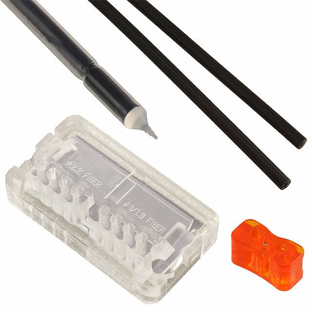
Contact Type Liquid Level Detection Fiber
Other
Products
FT-Z8Y
Chemical-resistant
FD-F4�/F9�
FD-F8Y
EX-F1
Liquid Leak / Liquid Level Sensing
SENSORS FOR
SEMICONDUCTOR INDUSTRY
FD-F8Y
Liquid adherence-free
fiber tip
Avoids liquid drop adherence
Immune against chemical agents
No metal ionization
Reduces malfunction due to adhering
of a liquid drop.
The fiber is totally covered with fluorine
resin. It can be immersed in chemicals.
The fiber is made of 100 % resin.
Hence, it does not release metal ions.
It can also be safely used in semiconductor manufacturing cleaning
equipment.
FD-F8Y
Conventional model
Liquid drop
The multistep
pointed end
makes adhering
of liquid drop.
Malfunction due to liquid
drop adherence
Heat-resistant up to 125 °C 257 °F and free-cut
It can be used in hot liquids since it is
heat resistant. Moreover, it can be cut
to any desired length.
Principle of detection
When the fiber tip is in the air, as there is a large difference between the air and
the tube refractive indexes, the tube boundary reflects the emitted beam back to
the receiver. On the other hand, when the fiber tip is immersed in a liquid, the
emitted beam scatters from the fiber into the liquid because of the small
difference in the liquid and the tube refractive indexes.
In the air
In liquid
Fiber
Tube
Air
Liquid
Air
Liquid
620
Ramco Innovations - 1207 Maple Street, West Des Moines IA USA 50265 - 800-280-6933 - www.ramcoinnovations.com
�APPLICATIONS
Liquid Leak / Liquid Level Sensing
FD-F4�/F9�
FD-F8Y
EX-F1
Detecting liquid level in a tank
Tank
FD-F8Y
ORDER GUIDE
Fiber
Fiber cable length
Allowable bending radius
:
(mm in)
Free-cut
"6
"0.236
2 m 6.562 ft
(Note)
Protective tube: R40 R1.575
Fiber: R15 R0.591
Model No.
Chemical-resistant
FT-Z8Y
Appearance (mm in)
FD-F8Y
Note: 1,000 mm 39.370 in from the amplifier insertion end is the cutting range.
Appearance
Model No.
Emitting
element
Output
FX-301
NPN open-collector transistor
FX-301P
PNP open-collector transistor
FX-302
NPN open-collector transistor
FX-302P
PNP open-collector transistor
High-functional
digital
Digital
Type
Quick-connection cable is not supplied with the amplifier. Please order it separately.
Other
Products
Amplifiers
High speed
digital
NPN open-collector transistor
FX-303P
PNP open-collector transistor
Manually set
Red LED
FX-303
FX-311
NPN open-collector transistor
FX-311P
PNP open-collector transistor
Ramco Innovations - 1207 Maple Street, West Des Moines IA USA 50265 - 800-280-6933 - www.ramcoinnovations.com
SENSORS FOR
SEMICONDUCTOR INDUSTRY
FD-F8Y
621
�ORDER GUIDE
Quick-connection cables Quick-connection cable is not supplied with the amplifier. Please order it separately.
Main cable
Main cable
Sub cable
Model No.
• CN-73-C1
• CN-73-C2
• CN-73-C5
Description
CN-73-C1
Length: 1 m
3.281 ft
CN-73-C2
Length: 2 m
6.562 ft
CN-73-C5
Length: 5 m
16.404 ft
CN-71-C1
Length: 1 m
3.281 ft
CN-71-C2
Length: 2 m
6.562 ft
CN-71-C5
Length: 5 m
16.404 ft
0.15 mm2 3-core cabtyre cable, with connector on one end
Cable outer diameter: "3.0 mm "0.118 in.
Sub cable
• CN-71-C1
• CN-71-C2
• CN-71-C5
0.15 mm2 1-core cabtyre cable, with connector on one end
Cable outer diameter: "3.0 mm "0.118 in.
End plates End plates are not supplied with the amplifier. Please order it separately when the amplifiers are mounted in cascade.
Appearance
Other
Products
FT-Z8Y
Chemical-resistant
FD-F4�/F9�
FD-F8Y
EX-F1
Liquid Leak / Liquid Level Sensing
Type
Model No.
MS-DIN-E
Description
When cascading multiple amplifiers, or when it moves
depending on the way it is installed on a DIN rail, these end
plates ensure that all amplifiers are mounted together in a
secure and fully connected manner.
Two pcs. per set
Accessories
• FX-CT2
• (Fiber cutter)
622
• FX-AT3
"2.2 mm "0.087 in fiber attachment
for FX-301/302/303/311 series
(
(
SENSORS FOR
SEMICONDUCTOR INDUSTRY
FD-F8Y
Ramco Innovations - 1207 Maple Street, West Des Moines IA USA 50265 - 800-280-6933 - www.ramcoinnovations.com
�SPECIFICATIONS
Refer to p.77/p.119/p.138/p.166 for amplifier specifications.
Fiber
Type
Reflective
Applicable amplifiers
FX-301(P), FX-302(P), FX-303(P), FX-311(P)
Sensing object
Liquid (Note 1)
Repeatability
Allowable bending radius
0.5 mm 0.020 in or less (with water)
Tube: R40 mm R1.575 in or more (Do not bend 32 mm 1.260 in length from the tip), Fiber cable: R15 mm R0.591 in or more
Fiber cable length
Ambient temperature (Note 3, 4)
2 m 6.562 ft free-cut (Do not cut the tube (Note 2))
�40 to�125 �C �40 to�257 �F (No dew condensation or icing allowed), Storage: �40 to�125� C �40 to�257 �F
Ambient humidity
35 to 85% RH, Storage: 35 to 85 % RH
�49 to�490 kPa
Ambient pressure (Note 3)
Material
Tube: Fluorine resin, Fiber sheath: Polypropylene
FX-CT2 (Fiber cutter): 1 pc. FX-AT3 ("2.2 mm "0.087 in fiber attachment for FX-301/302/303/311 series): 1 pc.
Accessory
Notes: 1) Unclear liquid may not be sensed stably.
Notes: 2) 1,000 mm 39.370 in from the amplifier insertion end is the cutting range.
Notes: 3) Liquid being detected should also be kept within the rated ambient temperature range.
Notes: 4) The ambient temperature and pressure under which these devices are used are set separately.
For usage with both of these at or near the maximum permissible value, please contact our office.
PRECAUTIONS FOR PROPER USE
Refer to p.1135l for general precautions and p.90/p.121/p.141/p.168l for amplifier precautions.
This product is not a safety sensor. Its use is not
intended or designed to protect life and prevent body
injury or property damage from dangerous parts of
machinery. It is a normal object detection sensor.
Cutting fiber cable
• The fiber cables should be cut off at the ends with the
fiber cutter FX-CT2 (accessory) before insertion into the
amplifier.
10 mm
0.394 in
Mounting
• Use a commercially available fluorine resin joint, etc., to
install FD-F8Y.
Possible cutting
range
Protective tube Fiber cable
• Do not scratch the fiber sheath while cutting the fluorine
resin tube.
Cutting procedure
Fluorine resin joint
• To cut the fiber cables, insert them from the direction
shown below.
(Fiber cable insertion direction)
Method of mounting (FX-AT3)
1
1 Confirm that the fiber lock
Upward: unlock
button of FX-AT3 is in unlock
3
side.
Downward: lock
2
2 Insert the fiber cables one by
one, in condition 1.
3 After inserting, press down
the fiber lock button. The
Fiber lock button
fiber cables are fixed at the
desired position. (In order to
unlock the fiber cables, press
the fiber lock button towards
unlock direction from the For "2.2 mm "0.087 in
fiber cable
opposite side.)
4 Insert the fiber cables into the
holes for "2.2 mm "0.087 in
fiber cable of the fiber cutter
(FX-CT2) from the direction shown in the figure above.
5 Cut both fiber cables simultaneously. (At this time, place
the attachment without any gap against the fiber cutter.
The fiber cables will be cut at a position approx. 10.5 mm
0.413 in from the tip of the fiber.)
6 After cutting, connect the fiber cables to the fiber sensor
amplifier immediately.
Free-cut fiber
without FT-AT3
attachment
Free-cut fiber
with FT-AT3
attachment
How to use fiber cutter (FX-CT2)
1 Slide part @ of the fiber cutter fully upward till it stops.
2 Insert the fiber cables, mounted in the attachment, till
they stop.
Take care that there are separate fiber cable insertion
holes for "2.2 mm "0.087 in and "1.0 mm "0.039 in
or "1.3 mm "0.051 in fiber cables.
Part@
3 Slide part @ of the fiber
cutter down to cut the fiber
cable.
For "2.2 mm "0.087 in
fiber cable
Notes: 1) The fiber cables should be cut in one stroke.
2) Once a fiber cable is cut off at a hole, do not use the hole again. If
used, it degrades the cut surface quality and the detectability may
deteriorate.
3) The blade cannot be replaced. Please purchase an additional fiber
cutter, if required.
4) Note that the sensing range may be reduced by up to 20 %
depending on the cut condition. Hence, decide the setting distance
by taking sufficient margin.
Ramco Innovations - 1207 Maple Street, West Des Moines IA USA 50265 - 800-280-6933 - www.ramcoinnovations.com
623
Liquid Leak / Liquid Level Sensing
FD-F4�/F9�
FD-F8Y
EX-F1
FD-F8Y
Chemical-resistant
FT-Z8Y
Model No.
Other
Products
Item
SENSORS FOR
SEMICONDUCTOR INDUSTRY
FD-F8Y
�PRECAUTIONS FOR PROPER USE
Refer to p.1135l for general precautions and p.90/p.121/p.141/p.168l for amplifier precautions.
Teaching
When using the FX-301(P) or the FX-302(P), FX-303(P)
• The threshold values can be set by either 2-level teaching
or limit teaching, when the MODE indicator / TEACH
(yellow) lights up.
• This is the method of setting the threshold value by teaching
only the water absent condition (not immersed condition).
Step
Function
Display
• This is the method of setting the threshold value by
teaching two levels, corresponding to the immersed
and not immersed conditions. Normally, setting is done
by this method.
Step
Function
The fibers are mounted in
the tank.
1 Press MODE key to light up
MODE indicator / TEACH
(yellow).
Press jog switch in the not immersed condition.
If the teaching is accepted, the read incident light
intensity blinks in the display.
Display
The fibers are mounted in
the tank.
1 Press MODE key to light up
MODE indicator / TEACH
(yellow).
Press jog switch in the fiber immersed condition.
If the teaching is accepted, the read incident light
intensity blinks in the digital display.
Fiber not immersed
2
3
MODE indicator / TEACH (yellow) blinks.
Turn jog switch to the ‘ � ’ side.
If jog switch is turned to the ‘ � ’ side, ‘
’ scrolls
(twice) the display from left to right, and the
threshold level is shifted to a
�
value approx. 15 % lower (higher
sensitivity) than that set at 2.
(Note 1)
Fiber immersed
2
High
OFF
4
Threshold
value
SENSORS FOR
SEMICONDUCTOR INDUSTRY
FD-F4�/F9�
FD-F8Y
EX-F1
Liquid Leak / Liquid Level Sensing
FT-Z8Y
Chemical-resistant
Other
Products
FD-F8Y
MODE indicator / TEACH (yellow) blinks.
Press jog switch in the fiber not immersed condition.
100 %
Incident light
intensity with fiber
not immersed
15 %
Threshold
value
ON
Fiber not immersed
Low
3
0
Turn to ‘�’ side
5
If the teaching is accepted, the read incident light
intensity blinks in the digital display and the
threshold value is set at the mid-value between the
incident light intensities in the immersed and the not
immersed conditions. After this, the judgment on the
4
stability of sensing is displayed.
• In case stable sensing is possible: ‘
’ is
displayed. Stability indicator (green) blinks.
• In case stable sensing is not possible: ‘
’ is
displayed. Stability indicator (green) is off.
5 The threshold value is displayed.
6
‘
7
The incident light intensity appears in the digital
display and the setting is complete.
’ blinks in the digital display.
After this, the judgment on whether the setting shift
amount can be shifted or not is displayed.
• In case shifting is possible: ‘
’ is displayed.
• In case shifting is not possible: ‘
’ is displayed.
6 The threshold value is displayed.
7 ‘
8
’ blinks in the digital display.
The incident light intensity appears in the digital
display and the setting is complete.
Notes: 1) The approx. 15 % amount of shift is the initial value. The amount of
shift can be changed in the PRO mode from approx. 5 to 80 %
(5 % step). Refer to ‘Fiber Sensor Guide Book’ or ‘SUNX fiber
sensor homepage’ (http://www.fiber-sensor.com) for details of the
setting method.
Notes: 2) Do not move or bend the fiber cable after the sensitivity setting.
Detection may become unstable.
Note: Do not move or bend the fiber cable after the sensitivity setting.
Detection may become unstable.
624
Ramco Innovations - 1207 Maple Street, West Des Moines IA USA 50265 - 800-280-6933 - www.ramcoinnovations.com
�Step
Sensing method
�Make sure that the
operation selection
switch is set to L-ON
(not immersed ON).
�In case ‘assist function’
is to be used, switch
1
the operation selection
switch in the order of LON (not immersed ON)
n D-ON (immersed
ON) n L-ON (not
immersed ON).
Fiber not immersed
2
Sensitivity adjustment
Fiber immersed
FX-311(P)
• Adjust the sensitivity,
: Lights up �: Lights off
observing the operation Sensing condition
MODE
Operation indicator
indicator (orange).
L-ON (ON when not immersed)
�
However, since the Immersed
D-ON (ON when immersed)
condition for lighting up
L-ON (ON when not immersed)
Not
of the indicator depends
Immersed D-ON (ON when immersed)
�
on the combination of
the sensing condition
and selected operation for L/D-ON, verify it from the table
on the right.
• The sensitivity adjuster is a 12-turn
Pointer
potentiometer. The maximum sensitivity
is obtained by turning it fully clockwise.
• The pointer shows the present
sensitivity level.
4
6
8
• This product incorporates an ‘assist
function’, which helps to easily search
the optimum sensitivity position by
blinking of the pointer.
• In order to make ‘assist function’ effective, switch the
operation selection switch in the order L-ON (not immersed
ON) n D-ON (immersed ON) n L-ON (not immersed ON).
0
MAX
Notes: 1) ‘Assist function’ turns off automatically once the sensitivity
adjustment has been completed.
Notes: 2) In case ‘assist function’ is not to be used, set the operation
selection switch to D-ON (immersed ON) and wait for 2 sec., or
more, to make ‘assist function’ ineffective.
DIMENSIONS (Unit: mm in)
FD-F8Y
Free-cut
1,000
39.370
(26) Bending pro(1.024) hibited range
16
8
0.315 0.630
(
)
3
Turn the sensitivity adjuster
fully counterclockwise.
(Minimum sensitivity)
0
In the fiber not immersed condition, slowly turn the adjuster
clockwise and find the point
@ where the sensor is
switched ON.
The pointer blinks once at the
point @ . (Note 1)
In the fiber immersed condition, slowly turn the adjuster further clockwise until
the sensor goes into the ON
state again. Once it is
switched on, turn the adjuster counterclockwise a
little and find the point b
where it is switched OFF.
The pointer blinks twice at
the point b. (Note 2)
If the sensor does not go
into the ON state, MAX is
the point b.
(
4
Sensitivity
indicator
Operation
MAX
ON
A
0
MAX
OFF
B
0
MAX
ON
)
Turn the adjuster towards
the point @ from the point
b slowly. The pointer starts
blinking when it approaches
the optimum sensitivity point
and blinks faster at the
optimum sensitivity point for
3 sec. This point is the
optimum sensitivity point.
(Note 2)
Optimum point
B
A
0
MAX
5 Select either L-ON (not immersed ON) or D-ON (immersed ON)
according to your application.
Notes: 1) When ‘assist function’ is not used, the pointer does not blink.
Notes: 2) When ‘assist function’ is not used, the middle point of @ and b is
regarded as the optimum sensitivity point.
Notes: 3) In order to protect the mechanism, the sensitivity adjuster idles
when over turned, which may result in a backlash of 1 to 2
divisions.
Notes: 4) Depending upon the sensing conditions, stable sensing may be
possible at a position which is slightly shifted from the optimum
sensitivity point.
Notes: 5) Do not move or bend the fiber cable after the sensitivity adjustment. Detection may become unstable.
The CAD data in the dimensions can be downloaded from the SUNX website: http://www.sunx.co.jp/
Refer to p.102/p.127/p.143/p.170 for amplifier dimensions.
With FX-AT3
1,000
39.370
(Allowable cutting range)
"2.2 "0.087�2
("6) ("0.236) protective tube (Fluorine resin)
Ramco Innovations - 1207 Maple Street, West Des Moines IA USA 50265 - 800-280-6933 - www.ramcoinnovations.com
SENSORS FOR
SEMICONDUCTOR INDUSTRY
Others
• Take care that unclear liquid may not be sensed stably.
• Take care that the tube may stretch by maximum 2 % of
the total length if it is used at a high temperature.
• Bending radius of the fiber cable must be R15 mm R0.591 in
or more (tube: R40 mm R1.575 in or more). However, do not
bend 32 mm 1.260 in length from the tip.
If the bending radius is smaller than the specified value, the
sensing performance may deteriorate.
• Do not use the fiber at places having intense vibrations,
as this can cause malfunction.
• Keep the fiber head surface intact. If it is scratched or
spoiled, the detectability will deteriorate.
• Ensure that any strong extraneous light is not incident on
the receiving face of the fiber head.
• Do not apply excessive tensile force to the fiber cable.
• Take care that the sensor is not directly exposed to
fluorescent light from a rapid-starter lamp or a high
frequency lighting device, as it may affect the sensing
performance.
Liquid Leak / Liquid Level Sensing
FD-F4�/F9�
FD-F8Y
EX-F1
Refer to p.1135l for general precautions and p.90/p.121/p.141/p.168l for amplifier precautions.
Other
Products
PRECAUTIONS FOR PROPER USE
Chemical-resistant
FT-Z8Y
FD-F8Y
625
�