133
FIBER
SENSORS
LASER
SENSORS
Digital Fiber Sensor
FX-410 SERIES
Related Information
■■General terms and conditions.............. F-3
■■Selection guide………………………… P.3~
SC..........................................................................P.987~
Glossary of terms....................................P.1549~
■■General precautions.................... P.1552~
Korea’s S-mark............................................ P.1602
PHOTOELECTRIC
SENSORS
MICRO
PHOTOELECTRIC
SENSORS
Recognition
(Excluding FX-412□)
AREA
SENSORS
Certified
(Excluding FX-412□ and PNP output type)
SAFETY LIGHT
CURTAINS /
SAFETY COMPONENTS
PRESSURE /
FLOW
SENSORS
INDUCTIVE
PROXIMITY
SENSORS
PARTICULAR
USE SENSORS
SENSOR
OPTIONS
SIMPLE
WIRE-SAVING
UNITS
WIRE-SAVING
SYSTEMS
MEASUREMENT
SENSORS
STATIC
CONTROL
DEVICES
LASER
MARKERS
PLC
HUMAN MACHINE
INTERFACES
ENERGY
MANAGEMENT
SOLUTIONS
FA COMPONENTS
MACHINE VISION
SYSTEMS
UV CURING
SYSTEMS
Selection
Guide
Fibers
panasonic.net/id/pidsx/global
PNP output
type available
Light intensity Interference
monitor
prevention
Timer
Just “Look” and “Turn”,
Simple, easy-to-use fiber sensor
Incident light intensity and threshold value
are displayed simultaneously
The incident light intensity and threshold value can be
checked at the same time with no operations needed. In
addition, no complex mode settings are needed when
the values are adjusted.
Easy-to-understand operating panel layout
The threshold value adjuster and operation mode switch
are large and easy to see, and they can be operated with
the same sensitivity as general-purpose photoelectric
sensors. Functions which are not commonly used can be
operated using a non-obtrusive setting switch.
Adjustment variations according to the
individual have been eliminated
Incident light
intensity
Accurate control of the adjuster threshold values by
using numerical values is possible due to the digital
display. This allows anybody to perform the same
settings.
Operation
mode
switch
Threshold
value
Fiber
Amplifiers
Setting switch
Other Products
FX-500
FX-550
Threshold value adjuster
FX-100
FX-410
Threshold values can be changed smoothly
This sensor uses the R.S.S.* adjuster with a compact encoder inside.
The sensitivity amount changes depending on the rotation speed of the adjuster, so that
adjustment can be carried out speedily.�
Slower [Turn]
Amount of change
(digit)
100
10
Faster [Turn]
1
Slower
Faster
Adjuster rotation speed
•
•
0°
ls 3
ua
it eq
g
1 di
•
* Rotation Speed Sensitivity
Adjustment in units of 1 digit is also easy
No need for the fine changes in force required
for photoelectric sensors.
�Digital Fiber Sensor
FX-410 SERIES
New concept
FX-412 can be turned by finger!� New concept
Standard screwdrivers can be used to turn the adjuster as well
as precision screwdrivers. In addition, an “endless” mechanism
is used which eliminates the possibility of any damage being
caused by turning the adjuster too far.
The adjuster can be turned directly by finger, without the
need for a screwdriver.
Large endless adjuster�
134
FIBER
SENSORS
LASER
SENSORS
PHOTOELECTRIC
SENSORS
MICRO
PHOTOELECTRIC
SENSORS
AREA
SENSORS
SAFETY LIGHT
CURTAINS /
SAFETY COMPONENTS
PRESSURE /
FLOW
SENSORS
INDUCTIVE
PROXIMITY
SENSORS
Everyday-use
screwdriver is OK
Beam power greatly increased to give strong performance
under adverse environments�
Red LED type
The beam power has been greatly increased. This
means a longer sensing distance and less trouble from
problems such as dust. These sensors have ample
performance for workplace needs.
1,550 mm
61.024 in
FX-411
Previous
models
(for U-LG mode)
1,100 mm
43.307 in
* For FT-42 thru-beam type fiber
Three types are available, with red, blue and green light
Different sensors can be selected to suit the application.
WIRE-SAVING
SYSTEMS
MEASUREMENT
SENSORS
1.4 times
previous
models
STATIC
CONTROL
DEVICES
LASER
MARKERS
PLC
The red LED type sensors have a “four-chemical emitting
element” which maintains stability of light emissions for
long-term operation. Furthermore, all models have an “APC
(Auto Power Control) circuit” which improves stability at
times such as when the power is turned on. These features
improve overall stability compared to previous models.
Light emitting amount
sensing comparison
Short-term stability
Deviation
SENSOR
OPTIONS
SIMPLE
WIRE-SAVING
UNITS
Improved stability over both long and short terms� Red LED type
● Stable
PARTICULAR
USE SENSORS
Color combinations that can be discerned during mark sensing
Mark
color
Background color
White
Yellow Orange
Red
Green
Blue
Black
HUMAN MACHINE
INTERFACES
White
ENERGY
MANAGEMENT
SOLUTIONS
Yellow
FA COMPONENTS
Orange
MACHINE VISION
SYSTEMS
Red
FX-411 (Red LED type)
UV CURING
SYSTEMS
Green
Three-chemical
emitting element,
Without APC
Blue
Black
Long-term stability
: Red LED type
: Blue LED type
: Green LED type
Selection
Guide
Fibers
Time
Connector type
Excellent workability and ease of maintenance�
The same quick-connection cable that is
used for sensors such as the FX-300 series
of digital fiber sensors is used. This means
that they can be used together with other
types of sensors such as laser sensors, and
the number of power supply cables can be
reduced.
Laser sensor
LS-401
Fiber sensor
FX-411
Fiber sensor
FX-411B
FX-411G
Up to a maximum 16 sensors can be connected together
Output line 3
Other Products
Fiber sensor
Sub cable
CN-71-C□
Main cable
CN-73-C□
Power Output line 1 Output line 2
supply
cable Main cable
Fiber
Amplifiers
Output line 16
Sub cable
A single output line is used, so that wiring can be greatly reduced and space savings can be obtained.
The sensors can be connected together with other
sensors such as the FX-300 series of digital fiber
sensors and the GA-311 of inductive proximity
sensors. In addition, the SC series of sensor PLC
connection units with MIL connector compatibility can
also be used to further reduce the amount of wiring
(P.987~).
Quick-connection cables can
be used for power supply
cascade wiring.
Both main and sub units utilize
the same amplifier body.
FX-500
FX-550
FX-100
FX-410
�135
FIBER
SENSORS
LASER
SENSORS
FX-410 SERIES
Digital Fiber Sensor
Contributing to device miniaturization
This fiber sensor is the smallest among the dual digital
display types, contributing to device miniaturization.
PHOTOELECTRIC
SENSORS
MICRO
PHOTOELECTRIC
SENSORS
AREA
SENSORS
SENSOR
OPTIONS
SIMPLE
WIRE-SAVING
UNITS
WIRE-SAVING
SYSTEMS
MEASUREMENT
SENSORS
STATIC
CONTROL
DEVICES
LASER
MARKERS
ENERGY
MANAGEMENT
SOLUTIONS
Light-emitting amount can be changed
without changing response time.
30.5 mm
1.201 in
FT-A11
Level 2
Wire breakage detection
10 mm
0.394 in
Equipped with 3 types timers
Equipped with OFF-delay / ON-delay / ONE SHOT timer.
(Timer period: 1 ms to 3 sec. approx.)
Time chart
For L-ON
The digital display can be turned upside-down if required
to suit the setup location. In addition, a stability indicator
is also provided, so that the amount of light-receiving
excess can be checked even when the display is turned
off.
Beam-received
Sensing
condition
Beam-interrupted
ON
T1
ON-delay
OFF
T1
OFF-delay
ONE SHOT
UV CURING
SYSTEMS
Selection
Guide
T1
T1
T1
ON
When digital
display is
upside-down
(turned ON)
Other Products
Adjuster is used so that operation can be
carried out confidently even when upside down.
OFF
ON
OFF
When digital
display is off
(Eco ON)
Stability indicator
Excess amount can be seen even when display is off
Interference prevention for up to 8 sets fiber heads (for U-LG)
Hold function
The optical communication function allows up to a
maximum of eight sets of fiber heads (four sets for
FAST and STD settings) to be installed in contact with
each other without mutual interference occurring. (Set
automatically when power is turned on.)
Peak and bottom hold values for the incident light
intensity can be displayed. This is useful for checking
the incident light intensity during tasks such as drop
detection.
In addition, the peak and bottom values can be checked
while looking at the threshold value, which makes
adjustment much easier.
Fibers
Fiber
Amplifiers
Level 1
Digital display upside-down / off function
FA COMPONENTS
MACHINE VISION
SYSTEMS
Level 4
Level 3
PLC
HUMAN MACHINE
INTERFACES
In cases where the incoming light level can become
saturated, such as during close-range sensing or when
sensing transparent or minute objects, the sensor’s lightemitting amount can be adjusted to provide more stable
sensing without changing the response time.
64.5 mm
2.539 in
SAFETY LIGHT
CURTAINS /
SAFETY COMPONENTS
PRESSURE /
FLOW
SENSORS
INDUCTIVE
PROXIMITY
SENSORS
PARTICULAR
USE SENSORS
Ideal for dealing with saturation / Light-emitting amount
Red LED type New concept
selection function
FD-61
Displayed sequentially
Dog
Hold function
setting display
FX-500
FX-550
FT-A11
FX-100
FX-410
Key lock function prevents wrong operation
This prevents the operator from changing the threshold
value by mistake.
Press and hold setting
switch for 5 seconds
Drop detection of minute objects
Bottom hold
amount display
Peak hold
amount display
�Digital Fiber Sensor
FX-410 SERIES
ORDER GUIDE
FIBER
SENSORS
LASER
SENSORS
Amplifiers Quick-connection cable is not supplied with the amplifier. Please order it separately.
Appearance
NPN output
PNP output NPN output
Type
Model No.
Emitting element
FX-411
Red LED
FX-411B
Blue LED
FX-411G
Green LED
FX-411P
Red LED
FX-411BP
Blue LED
FX-411GP
Green LED
FX-412 (Note)
Red LED
FX-412B (Note)
Blue LED
FX-412G (Note)
Green LED
PHOTOELECTRIC
SENSORS
Output
MICRO
PHOTOELECTRIC
SENSORS
NPN open-collector transistor
AREA
SENSORS
SAFETY LIGHT
CURTAINS /
SAFETY
COMPONENTS
PRESSURE /
FLOW
SENSORS
PNP open-collector transistor
INDUCTIVE
PROXIMITY
SENSORS
PARTICULAR
USE
SENSORS
NPN open-collector transistor
SENSOR
OPTIONS
SIMPLE
WIRE-SAVING
UNITS
Note: The FX-412□ has a threshold value adjuster that can be adjusted with your fingers.
Quick-connection cables
Type
Sub cable
(1-core)
WIRE-SAVING
SYSTEMS
MEASUREMENT
SENSORS
Quick-connection cable is not supplied with the amplifier. Please order it separately.
Model No.
Main cable
(3-core)
136
Description
CN-73-C1
Length: 1 m 3.281 ft
CN-73-C2
Length: 2 m 6.562 ft
CN-73-C5
Length: 5 m 16.404 ft
CN-71-C1
Length: 1 m 3.281 ft
CN-71-C2
Length: 2 m 6.562 ft
CN-71-C5
Length: 5 m 16.404 ft
Main cable
STATIC
CONTROL
DEVICES
• CN-73-C□
LASER
MARKERS
0.2 mm 3-core cabtyre cable,
with connector on one end
Cable outer diameter: �ø3.3 mm
ø0.130 in
2
0.2 mm2 1-core cabtyre cable,
with connector on one end
Cable outer diameter: �ø3.3 mm
ø0.130 in
PLC
HUMAN
MACHINE
INTERFACES
Sub cable
ENERGY
MANAGEMENT
SOLUTIONS
• CN-71-C□
FA
COMPONENTS
MACHINE
VISION
SYSTEMS
End plates
End plates are not supplied with the amplifier. Please order them separately when the amplifiers are mounted in cascade.
Appearance
Model No.
MS-DIN-E
Description
When amplifiers are mounted in cascade, or when
an amplifier moves depending on the way it is
installed on a DIN rail, these end plates clamp
amplifiers into place on both sides. Make sure to
use end plates when cascading multiple
amplifiers together.
Selection
Guide
Fibers
Fiber
Amplifiers
Other
Products
2 pcs. per set
FX-500
OPTIONS
FX-550
Designation
Model No.
Amplifier
mounting bracket
MS-DIN-2
Mounting bracket for amplifier
FX-MB1
10 sets of 2 communication window seals and 1 connector seal
Communication window seal:
It prevents malfunction due to transmission signal from another
amplifier, as well as, prevents effect on another amplifier.
Connector seal:
It prevents contact of any metal, etc., with the pins of the
quick-connection cable.
Fiber amplifier
protection seal
UV
CURING
SYSTEMS
Description
Amplifier mounting bracket
• MS-DIN-2
Fiber amplifier protection seal
• FX-MB1
Communication
window seal
Connector seal
FX-100
FX-410
�137
FIBER
SENSORS
LASER
SENSORS
PHOTOELECTRIC
SENSORS
MICRO
PHOTOELECTRIC
SENSORS
AREA
SENSORS
SAFETY LIGHT
CURTAINS /
SAFETY
COMPONENTS
PRESSURE /
FLOW
SENSORS
INDUCTIVE
PROXIMITY
SENSORS
Digital Fiber Sensor
FX-410 SERIES
LIST OF FIBERS
Thru-beam type (one pair set)
Fibers are listed in alphabetic order. Refer to “Fiber Selection p.5~” for details of each fiber.
Sensing range (mm in) (Note 1)
Red LED
Model No.
U-LG
FT-140
STD
Blue LED
FAST
U-LG
STD
Green LED
FAST
U-LG
STD
Dimensions
FAST
19,600 771.654 (Note 2) 16,000 629.921 15,000 590.551 14,000 551.181 3,300 129.921 2,200 86.614 9,500 374.016 2,500 98.425 1,800 70.866 P.63
FT-30
600 23.622
145 5.709
95 3.740
90 3.543
24 0.945
15 0.591
45 1.772
12 0.472
8 0.315 P.63
FT-31
540 21.260
140 5.512
85 3.346
85 3.346
20 0.787
14 0.551
38 1.496
10 0.394
7 0.276 P.63
FT-31S
540 21.260
140 5.512
85 3.346
85 3.346
20 0.787
14 0.551
38 1.496
10 0.394
7 0.276 P.63
380 14.961
80 3.150
55 2.165
53 2.087
16 0.630
9 0.354
28 1.102
7 0.276
4 0.157 P.63
3,600 141.732 (Note 2) 1,190 46.850
870 34.252
860 33.858
220 8.661
145 5.709
450 17.717
120 4.724
80 3.150 P.63
FT-31W
FT-32
FT-40
1,600 62.922
345 13.583
245 9.646
250 9.843
65 2.559
45 1.772
140 5.512
40 1.575
25 0.984 P.63
FT-42
1,550 61.024
340 13.386
240 9.449
230 9.055
60 2.362
40 1.575
125 4.921
33 1.299
22 0.866 P.63
FT-42S
1,550 61.024
340 13.386
240 9.449
230 9.055
60 2.362
40 1.575
125 4.921
33 1.299
22 0.866 P.63
FT-42W
1,300 51.181
290 11.417
210 8.268
220 8.661
57 2.244
33 1.299
110 4.331
32 1.260
19 0.748 P.63
SIMPLE
WIRE-SAVING
UNITS
FT-43
2,200 86.614
450 17.717
310 12.205
460 18.110
120 4.724
75 2.953
250 9.843
62 2.441
44 1.732 P.64
FT-45X
1,600 62.992
370 14.567
280 11.024
260 10.236
64 2.520
45 1.772
130 5.118
34 1.339
23 0.906 P.64
WIRE-SAVING
SYSTEMS
FT-A11
3,600 141.732 (Note 2) 2,400 94.488 1,800 70.866 1,300 51.181
350 13.780
220 8.661
770 30.315
190 7.480
120 4.724 P.64
FT-A11W
3,600 141.732 (Note 2) 2,500 98.425 2,000 78.740 1,300 51.181
350 13.780
220 8.661
550 21.654
150 5.906
130 5.118 P.64
FT-A32
3,600 141.732 (Note 2) 3,600 141.732 (Note 2) 3,600 141.732 (Note 2) 2,500 98.425
750 29.528
380 14.961 1,500 59.055
220 8.661
130 5.118 P.64
FT-A32W
3,600 141.732 (Note 2) 3,600 141.732 (Note 2) 3,600 141.732 (Note 2) 3,400 133.858
800 31.496
470 18.504 2,100 82.677
330 12.992
140 5.512 P.64
PARTICULAR
USE
SENSORS
SENSOR
OPTIONS
MEASUREMENT
SENSORS
STATIC
CONTROL
DEVICES
LASER
MARKERS
PLC
HUMAN
MACHINE
INTERFACES
ENERGY
MANAGEMENT
SOLUTIONS
FA
COMPONENTS
MACHINE
VISION
SYSTEMS
UV
CURING
SYSTEMS
Selection
Guide
Fibers
Fiber
Amplifiers
Other
Products
FX-500
FX-550
FX-100
FX-410
FT-AL05
FT-E13
FT-E23
FT-H13-FM2
1,100 43.307
240 9.449
180 7.087
220 8.661
30 1.181
7 0.276
5 0.197
2.5 0.098
110 4.331
20 0.787
15 0.591
12 0.472
55 2.165
–
3 0.118
35 1.378
–
125 4.921
1 0.039
2 0.079
6 0.236
9 0.354
150 5.906
30 1.181
–
1 0.039
P.64
–
P.64
1,100 43.307
280 11.024
200 7.874
50 1.969
13 0.512
FT-H20-J20-S (Note 3)
700 27.559
160 6.299
110 4.331
120 4.724
20 0.787
–
60 2.362
–
–
P.65
FT-H20-J30-S (Note 3)
700 27.559
160 6.299
110 4.331
120 4.724
20 0.787
–
60 2.362
–
–
P.65
FT-H20-J50-S (Note 3)
700 27.559
160 6.299
110 4.331
120 4.724
20 0.787
–
60 2.362
–
–
P.65
FT-H20-M1
550 21.654
150 5.906
100 3.937
100 3.937
25 0.984
FT-H20-VJ50-S (Note 3) 1,100 43.307
240 9.449
170 6.693
170 6.693
35 1.378
–
90 3.543
–
–
P.65
FT-H20-VJ80-S (Note 3) 1,100 43.307
240 9.449
170 6.693
170 6.693
35 1.378
–
90 3.543
–
–
P.65
FT-H20W-M1
400 15.748
110 4.331
80
3.15
75 2.953
19 0.748
13 0.512
58 2.283
13 0.512
9 0.354 P.65
FT-H30-M1V-S (Note 4)
390 15.354
100 3.937
70 2.756
75 2.953
20 0.787
15 0.591
55 2.165
13 0.512
10 0.394 P.65
FT-H35-M2
600 23.622
150 5.906
110 4.331
115 4.528
28 1.102
20 0.787
90 3.543
20 0.787
14 0.551 P.65
FT-H35-M2S6
600 23.622
150 5.906
110 4.331
115 4.528
28 1.102
20 0.787
90 3.543
20 0.787
14 0.551 P.65
FT-HL80Y
3,500 137.795 (Note 2)
800 31.496
550 21.654
150 5.906
35 1.378
20 0.787
200 7.874
55 2.165
35 1.378 P.66
FT-KS40
3,600 141.732 (Note 2) 2,000 78.740 1,900 74.803 1,000 39.370
270 10.630
190 7.480
20 0.787
65 2.559
16 0.630
20 0.787 P.64
–
17 0.669
10 0.394 P.65
12 0.472 P.65
53 2.087 P.66
590 23.228
130 5.118
FT-KV26
880 34.646
170 6.693
120 4.724
130 5.118
31 1.220
–
90 3.543
18 0.709
–
P.66
FT-KV26H1
790 31.102
150 5.906
100 3.937
115 4.528
28 1.102
–
80 3.150
16 0.630
–
P.66
FT-KV40
3,600 141.732 (Note 2) 1,700 66.929 1,300 51.181 1,200 47.244
310 12.205
190 7.480
800 31.496
190 7.480
FT-KV40W
3,600 141.732 (Note 2) 1,600 62.992 1,100 43.307
900 35.433
270 10.630
140 5.512
420 16.535
100 3.937
65 2.559 P.66
FT-L80Y
3,500 137.795 (Note 2)
250 9.843
60 2.362
40 1.575
300 11.811
70 2.756
45 1.772 P.66
900 35.433
600 23.622
120 4.724 P.66
FT-R31
380 14.961
79 3.110
56 2.205
80 3.150
20 0.787
13 0.512
38 1.496
10 0.394
7 0.276 P.66
FT-R40
1,200 47.244
240 9.449
170 6.693
200 7.874
50 1.969
32 1.260
100 3.937
28 1.102
19 0.748 P.66
FT-R41W
1,200 47.244
290 11.417
200 7.874
220 8.661
57 2.244
33 1.299
100 3.937
26 1.024
18 0.709 P.66
FT-R42W
3,600 141.732 (Note 2)
990 38.976
740 29.134
310 12.205
75 2.953
58 2.283
270 10.630
70 2.756
50 1.969 P.66
FT-R43
1,200 47.244
230 9.055
160 6.299
200 7.874
50 1.969
32 1.260
100 3.937
26 1.024
18 0.709 P.67
FT-R44Y
1,200 47.244
230 9.055
160 6.299
200 7.874
50 1.969
32 1.260
100 3.937
26 1.024
18 0.709 P.67
FT-R60Y
3,600 141.732 (Note 2)
750 29.528
540 21.260
560 22.047
140 5.512
90 3.543
290 11.417
75 2.953
50 1.969 P.67
FT-S11
150 5.906
30 1.181
20 0.787
21 0.827
5 0.197
3.5 0.138
12 0.472
2 0.079
1.5 0.059 P.67
FT-S20
600 23.622
145 5.709
95 3.740
90 3.543
24 0.945
15 0.591
45 1.772
12 0.472
8 0.315 P.67
FT-S21
540 21.260
140 5.512
85 3.346
85 3.346
20 0.787
14 0.551
38 1.496
10 0.394
7 0.276 P.67
Notes: 1) Note that the sensing range of the free-cut type fiber may be reduced by 20 % max. depending upon how the fiber is cut.
2) The fiber cable length practically limits the sensing range.
3) Heat-resistant joint fibers and ordinary-temperature fibers (FT-42) are sold as a set. Please refer to p.37 for details.
4) Sold as a set comprising vacuum type fiber + photo-terminal (FV-BR1) + fiber at atmospheric side (FT-J8). Please refer to p.39 for details.
�Digital Fiber Sensor
FX-410 SERIES
138
LIST OF FIBERS
FIBER
SENSORS
Thru-beam type (one pair set)
LASER
SENSORS
Fibers are listed in alphabetic order. Refer to “Fiber Selection p.5~” for details of each fiber.
PHOTOELECTRIC
SENSORS
Sensing range (mm in) (Note 1)
Model No.
Red LED
U-LG
Blue LED
Green LED
STD
FAST
U-LG
STD
380 14.961
80 3.150
55 2.165
53 2.087
16 0.630
9 0.354
FT-S22
910 35.827
190 7.480
140 5.512
110 4.331
29 1.142
FT-S30
1,600 62.992
345 13.583
245 9.646
250 9.843
65 2.559
FT-S31W
1,300 51.181
290 11.417
210 8.268
220 8.661
FT-S32
3,600 141.732 (Note 2)
920 36.220
670 26.378
FT-V23
720 28.346
140 5.512
100 3.937
FT-V24W
140 5.512
25 0.984
20 0.787
FT-V25
360 14.173
70 2.756
50 1.969
57 2.244
10 0.394
7 0.276
28 1.102
8 0.315
5 0.197 P.68
FT-V30
770 30.315
160 6.299
120 4.724
210 8.268
47 1.850
28 1.102
100 3.937
22 0.866
10 0.394 P.68
FT-V40
3,600 141.732 (Note 2)
950 37.402
730 28.740
810 31.890
190 7.480
130 5.118
500 19.685
115 4.528
81 3.189 P.68
1,500 59.055
350 13.780
250 9.843
240 9.449
55 2.165
35 1.378
180 7.087
38 1.496
24 0.945 P.68
390 15.354
80 3.150
55 2.165
64 2.520
16 0.630
10 0.394
30 1.181
7 0.276
5 0.197 P.68
FT-S21W
FT-V80Y
FT-Z20HBW
FAST
U-LG
STD
Dimensions
FAST
28 1.102
7 0.276
4 0.157 P.67
17 0.669
70 2.756
18 0.709
11 0.433 P.67
45 1.772
140 5.512
40 1.575
25 0.984 P.67
57 2.244
33 1.299
110 4.331
32 1.260
19 0.748 P.68
700 27.559
180 7.087
110 4.331
400 15.748
92 3.622
62 2.441 P.68
120 4.724
30 1.181
20 0.787
65 2.559
16 0.630
9 0.354 P.68
18 0.709
2 0.079
–
5 0.197
–
–
P.68
FT-Z20W
1,300 51.181
270 10.630
190 7.480
170 6.693
39 1.535
23 0.906
92 3.622
19 0.748
11 0.433 P.68
FT-Z30
3,100 122.047
660 25.984
480 18.898
640 25.197
160 6.299
100 3.937
320 12.598
87 3.425
59 2.323 P.68
FT-Z30E
3,600 141.732 (Note 2) 1,200 47.244
920 36.220
960 37.795
250 9.843
160 6.299
460 18.110
120 4.724
83 3.268 P.69
FT-Z30EW
3,600 141.732 (Note 2)
430 16.929
940 37.008
180 7.087
110 4.331
400 15.748
85 3.346
56 2.205 P.69
FT-Z30H
3,600 141.732 (Note 2) 1,300 51.181
950 37.402 1,100 43.307
290 11.417
170 6.693
580 22.835
150 5.906
100 3.937 P.69
FT-Z30HW
3,600 141.732 (Note 2) 1,300 51.181
950 37.402
940 37.008
180 7.087
110 4.331
400 15.748
85 3.346
56 2.205 P.69
590 23.228
FT-Z30W
2,400 94.488
540 21.260
390 15.354
490 19.291
120 4.724
83 3.268
240 9.449
67 2.638
45 1.772 P.69
FT-Z40HBW
1,300 51.181
290 11.417
210 8.268
220 8.661
57 2.244
33 1.299
110 4.331
32 1.260
19 0.748 P.69
FT-Z40W
2,200 86.614
460 18.110
340 13.386
380 14.961
90 3.543
63 2.480
170 6.693
45 1.772
30 1.181 P.69
FT-Z802Y
3,500 137.795 (Note 2)
750 29.528
540 21.260
450 17.717
110 4.331
80 3.150
300 11.811
80 3.150
60 2.362 P.69
Notes: 1) Note that the sensing range of the free-cut type fiber may be reduced by 20 % max. depending upon how the fiber is cut.
2) The fiber cable length practically limits the sensing range.
MICRO
PHOTOELECTRIC
SENSORS
AREA
SENSORS
SAFETY LIGHT
CURTAINS /
SAFETY
COMPONENTS
PRESSURE /
FLOW
SENSORS
INDUCTIVE
PROXIMITY
SENSORS
PARTICULAR
USE
SENSORS
SENSOR
OPTIONS
SIMPLE
WIRE-SAVING
UNITS
WIRE-SAVING
SYSTEMS
MEASUREMENT
SENSORS
STATIC
CONTROL
DEVICES
LASER
MARKERS
PLC
HUMAN
MACHINE
INTERFACES
ENERGY
MANAGEMENT
SOLUTIONS
FA
COMPONENTS
MACHINE
VISION
SYSTEMS
Retroreflective type
UV
CURING
SYSTEMS
Fibers are listed in alphabetic order. Refer to “Fiber Selection p.5~” for details of each fiber.
Sensing range (mm in) (Note 1,2)
Model No.
Red LED
U-LG
STD
Blue LED
FAST
U-LG
Green LED
Dimensions
STD
FAST
U-LG
STD
FAST
–
–
–
–
–
P.70
–
P.70
FR-KZ22E
15 to 350 0.591 to 13.780 15 to 140 0.591 to 5.512 15 to 100 0.591 to 3.937 20 to 100 0.787 to 3.937
FR-KZ50E
20 to 400 0.787 to 15.748 20 to 200 0.787 to 7.874 20 to 200 0.787 to 7.874 20 to 200 0.787 to 7.874 20 to 84 0.787 to 3.307 20 to 45 0.787 to 1.771 20 to 180 0.787 to 7.087 20 to 55 0.787 to 1.969
FR-KZ50H
20 to 400 0.787 to 15.748 20 to 200 0.787 to 7.874 20 to 200 0.787 to 7.874 20 to 145 0.787 to 5.709 20 to 47 0.787 to 1.850 20 to 26 0.787 to 1.024 20 to 145 0.787 to 5.709 20 to 47 0.787 to 1.850 20 to 26 0.787 to 1.024 P.70
FR-Z50HW
100 to 1,000 3.937 to 39.370 100 to 540 3.937 to 21.260 100 to 460 3.937 to 18.110 100 to 490 3.937 to 19.291
–
–
–
–
–
P.70
Notes: 1) Note that the sensing range of the free-cut type fiber may be reduced by 20 % max. depending upon how the fiber is cut.
The sensing range of FR-KZ22E is specified for the attached reflector. The sensing range of FR-KZ50E and FR-KZ50H is specified for the attached
reflector RF-003. The sensing range of FR-Z50HW is specified for the reflective tape RF-13.
2) The sensing range is the possible setting range for the attached reflector. The fiber can detect an object less than setting range for the reflector.
However, note that if there are any white or highly-reflective surfaces near the fiber head, reflected incident light may affect the fiber head. If this occurs,
adjust the threshold value of the amplifier unit before use.
Sensing range when using in combination with FR-Z50HW reflector (Optional)
The sensing ranges are the value for red LED types.
Reflector
Model No.
Sensing range (mm in)
FX-411
U-LG
STD
FAST
RF-230
100 to 12,000 3.937 to 47.244 100 to 1,700 3.937 to 66.929 100 to 1,300 3.937 to 51.181
RF-220
100 to 2,200 3.937 to 8.661 100 to 950 3.937 to 37.402 100 to 730 3.937 to 28.740
RF-210
100 to 2,100 3.937 to 82.677 100 to 780 3.937 to 30.709 100 to 620 3.937 to 24.409
Note: �The sensing range is the possible setting range for the reflector. The fiber can detect an object less than setting range for the reflector. However, note that if
there are any white or highly-reflective surfaces near the fiber head, reflected incident light may affect the fiber head. If this occurs, adjust the threshold value
of the amplifier unit before use.
Selection
Guide
Fibers
Fiber
Amplifiers
Other
Products
FX-500
FX-550
FX-100
FX-410
�139
FIBER
SENSORS
Digital Fiber Sensor
FX-410 SERIES
LIST OF FIBERS
LASER
SENSORS
Reflective type
PHOTOELECTRIC
SENSORS
Fibers are listed in alphabetic order. Refer to “Fiber Selection p.5~” for details of each fiber.
MICRO
PHOTOELECTRIC
SENSORS
AREA
SENSORS
SAFETY LIGHT
CURTAINS /
SAFETY
COMPONENTS
PRESSURE /
FLOW
SENSORS
INDUCTIVE
PROXIMITY
SENSORS
PARTICULAR
USE
SENSORS
SENSOR
OPTIONS
SIMPLE
WIRE-SAVING
UNITS
Sensing range (mm in) (Note 1, 2) / Description
Red LED
Model No.
U-LG
Blue LED
STD
FAST
U-LG
STD
Green LED
FAST
U-LG
STD
Dimensions
FAST
FD-30
200 7.874
48 1.890
35 1.378
40 1.575
9 0.354
6 0.236
18 0.709
5 0.197
3 0.118 P.71
FD-31
175 6.890
45 1.772
34 1.339
35
8
5 0.197
16
4 0.157
2 0.079 P.71
FD-31W
120 4.724
20 0.787
15 0.591
16 0.630
FD-32G
240 9.449
52 2.047
38 1.496
48 1.890
11 0.433
8 0.315
FD-32GX
320 12.598
50 1.969
38 1.496
50 1.969
12 0.472
9 0.354
FD-34G
150 5.906
30 1.181
22 0.866
19 0.748
5 0.197 0.2 to 3 0.008 to 0.118
10 0.394 0.3 to 2.5 0.012 to 0.098 0.4 to 1.5 0.016 to 0.059 P.71
FD-40
200 7.874
48 1.890
35 1.378
40 1.575
9 0.354
6 0.236
18 0.709
5 0.197
3 0.118 P.71
FD-41
175 6.890
45 1.772
34 1.339
35 1.378
8 0.315
5 0.197
16 0.630
4 0.157
2 0.079 P.71
FD-41S
175 6.890
40 1.575
30 1.181
35 1.378
8 0.315
5 0.197
16 0.630
4 0.157
1.378
0.315
3 0.118 1 to 2.5 0.039 to 0.098
0.630
7 0.276 1 to 2.5 0.039 to 0.098
–
P.71
24 0.945
5 0.197
4 0.157 P.71
24 0.945
7 0.276
4 0.157 P.71
2 0.079 P.71
–
FD-41SW
120 4.724
20 0.787
15 0.591
18 0.709 1 to 4 0.039 to 0.157 1 to 2.5 0.039 to 0.098
12 0.472 1 to 2.5 0.039 to 0.098
FD-41W
330 12.992
70 2.756
50 1.969
54 2.126 0.5 to 13 0.020 to 0.512 1 to 8 0.039 to 0.315
29 1.142 1.5 to 7 0.059 to 0.276 1.5 to 4.5 0.059 to 0.177 P.72
FD-42G
240 9.449
52 2.047
38 1.496
48 1.890
11 0.433
8 0.315
24 0.945
5 0.197
4 0.157 P.72
FD-42GW
240 9.449
40 1.575
30 1.181
30 1.181
7 0.276
5 0.197
15 0.591
4 0.157
2 0.079 P.72
FD-60
600 23.622
150 5.906
100 3.937
130 5.118
30 1.181
20 0.787
70 2.756
20 0.787
13 0.512 P.72
FD-61
510 20.079
140 5.512
90 3.543
105 4.134
27 1.063
18 0.709
65 2.559
16 0.630
11 0.433 P.72
LASER
MARKERS
FD-61G
460 18.110
110 4.331
80 3.150
105 4.134
27 1.063
18 0.709
55 2.165
15 0.591
9 0.354 P.72
FD-61S
500 19.685
140 5.512
95 3.740
105 4.134
27 1.063
18 0.709
65 2.559
16 0.630
11 0.433 P.72
PLC
FD-61W
330 12.992
70 2.756
50 1.969
54 2.126 0.5 to 13 0.020 to 0.512 1 to 8 0.039 to 0.315
29 1.142 1.5 to 7 0.059 to 0.276 1.5 to 4.5 0.059 to 0.177 P.73
FD-62
820 32.283
180 7.087
130 5.118
160 6.299 1 to 44 0.039 to 1.732 1 to 29 0.039 to 1.142
98 3.858 1 to 26 0.039 to 1.024 1 to 18 0.039 to 0.709 P.73
FD-64X
380 14.961
80 3.150
55 2.165
54 2.126 0.5 to 14 0.020 to 0.551 0.5 to 9 0.020 to 0.354
27 1.063 0.5 to 7 0.020 to 0.276 0.5 to 4.5 0.020 to 0.177 P.73
FD-A16
200 7.874
100 3.937
75 2.953
30 1.181
13 0.512
13 0.512
57 2.244
14 0.551
FD-AL11
460 18.110
100 3.937
70 2.756
70 2.756
17 0.669
10 0.394
45 1.772
9 0.354
WIRE-SAVING
SYSTEMS
MEASUREMENT
SENSORS
STATIC
CONTROL
DEVICES
HUMAN
MACHINE
INTERFACES
ENERGY
MANAGEMENT
SOLUTIONS
FA
COMPONENTS
MACHINE
VISION
SYSTEMS
UV
CURING
SYSTEMS
Fibers
FX-500
FX-550
FX-100
FX-410
6 0.236 P.73
–
20 0.787
4 0.157
3 0.118
2.5 0.098
0.7 0.028
FD-E23
75 2.953
15 0.591
10 0.394
10 0.394
2.5 0.098
1.5 0.059
5 0.197
1.3 0.051
0.9 0.035 P.73
FD-EG30
90 3.543
15 0.591
10 0.394
10 0.394
2.5 0.098
1.5 0.059
5 0.197
1.3 0.051
0.9 0.035 P.73
FD-EG30S
85 3.346
15 0.591
10 0.394
10 0.394
2.5 0.098
1.5 0.059
5 0.197
FD-EG31
25 0.984
5 0.197
4 0.157
4 0.157
1 0.039
0.5 0.020
2 0.079
FD-F41
Fiber
Amplifiers
Other
Products
–
P.73
FD-E13
FD-FA93
FD-H13-FM2
FD-H18-L31
1.3 0.051
–
P.73
0.9 0.035 P.74
–
P.74
P.74
Applicable pipe diameter: Outer dia. ø6 to ø26 mm ø0.236 to ø1.024 in transparent pipe
[PVC (vinyl chloride), fluorine resin, polycarbonate, acrylic, glass, wall thickness 1 to 3 mm 0.039 to 0.118 in]
Liquid absent: Beam received, Liquid present: Beam not received
P.74
ø4 mm ø0.157 in
Protective tube: Fluorine resin, length 500 mm 19.685 in (cuttable)
Liquid surface not contacted: Beam received, Liquid surface contacted: Beam not received
FD-F41Y
FD-F8Y
1.5 0.059
Applicable pipe diameter: Outer dia. ø6 to ø26 mm ø0.236 to ø1.024 in transparent pipe
[PFA (fluorine resin) or equivalently transparent pipe, wall thickness 1 mm 0.039 in]
Liquid absent: Beam received, Liquid present: Beam not received
FD-F4
Selection
Guide
–
–
P.71
–
–
–
–
–
–
–
–
P.74
–
Applicable pipe diameter: Outer dia. ø8 mm ø0.315 in or more transparent pipe
(When used with the tying bands: ø8 to ø80 mm ø0.315 to ø3.150 in)
[PFA (fluorine resin), including translucent] Liquid absent: Beam received, Liquid present: Beam not received
430 16.929
100 3.937
70 2.756
0 to 25 0 to 0.984 0 to 10 0 to 0.394 0 to 8 0 to 0.315
40 1.575
–
10 0.394
–
7 0.276
–
40 1.575
–
10 0.394
–
P.74
P.74
7 0.276 P.75
–
P.75
FD-H20-21
350 13.780
90 3.543
65 2.559
65 2.559
13 0.512
9 0.354
45 1.772
10 0.394
7 0.276 P.75
FD-H20-M1
270 10.630
85 3.346
60 2.362
60 2.362
14 0.551
10 0.394
58 2.283
10 0.394
7 0.276 P.75
2.5 to 29
4 to 20
4 to 16
–
–
–
–
–
FD-H25-L43
0.098 to 1.142 0.157 to 0.787 0.157 to 0.630
5 to 42
7 to 38
7 to 35
–
–
–
–
–
FD-H25-L45
0.197 to 1.654 0.276 to 1.496 0.276 to 1.437
Notes: 1) The standard sensing objects of the sensing ranges vary depending on the fibers.
2) Note that the sensing range of the free-cut type fiber may be reduced by 20 % max. depending upon how the fiber is cut.
–
P.75
–
P.75
�Digital Fiber Sensor
FX-410 SERIES
140
LIST OF FIBERS
FIBER
SENSORS
Reflective type
LASER
SENSORS
Fibers are listed in alphabetic order. Refer to “Fiber Selection p.5~” for details of each fiber.
PHOTOELECTRIC
SENSORS
Sensing range (mm in) (Note 1, 2) / Description
Red LED
U-LG
STD
FAST
U-LG
STD
FAST
FD-H30-KZ1V-S
(Note 3)
FD-H30-L32
FD-H30-L32V-S
(Note 3)
FD-H35-20S
20 to 300
25 to 100
25 to 45
0.787 to 11.811 0.984 to 3.937 0.984 to 1.772
–
–
–
–
–
–
P.76
0 to 20 0 to 0.787 1 to 8 0.039 to 0.315 1 to 6 0.039 to 0.236
–
–
–
–
–
–
P.76
SAFETY LIGHT
CURTAINS /
SAFETY
COMPONENTS
0 to 11
1.5 to 5
2 to 4
0 to 0.433 0.059 to 0.197 0.079 to 0.157
–
–
–
–
–
–
P.76
PRESSURE /
FLOW
SENSORS
U-LG
STD
Blue LED
FAST
Green LED
7 0.276
20 0.787
6 0.236
Dimensions
MICRO
PHOTOELECTRIC
SENSORS
Model No.
AREA
SENSORS
210 8.268
50 1.969
35 1.378
45 1.772
10 0.394
4 0.157 P.76
FD-H35-M2
300 11.811
83 3.268
60 2.362
50 1.969
12 0.472
9 0.354
50 1.969
10 0.394
7 0.276 P.76
FD-H35-M2S6
300 11.811
80 3.150
50 1.969
50 1.969
14 0.551
10 0.394
40 1.575
10 0.394
7 0.276 P.76
ø4 mm ø0.157 in Protective tube: fluorine resin, length:500 mm 19.685 in (allowable cutting)
Liquid surface not contacted: Beam received, Liquid surface contacted: Beam not received
FD-HF40Y
FD-L10
0 to 4.4 0 to 0.173 0 to 4 0 to 0.157 0 to 3.8 0 to 0.150
3.5 0.138
2.5 0.098
FD-L11
0 to 10 0 to 0.394 0 to 7 0 to 0.276 0 to 7 0 to 0.276
8.5 0.335
6 0.236
FD-L12W
0.5 to 10 0.020 to 0.394 1 to 4.5 0.039 to 0.177 1 to 3.5 0.039 to 0.137
–
–
2 0.079 0 to 3 0 to 0.118 1 to 2 0.039 to 0.079
5.5 0.217
–
8 0.315
–
5 0.197
–
P.76
–
P.77
–
P.77
–
P.77
–
P.77
FD-L20H
1 to 32 0.039 to 1.260 4 to 10 0.157 to 0.394 4.5 to 10 0.177 to 0.394 4 to 13 0.157 to 0.512 5 to 9 0.197 to 0.354 5.5 to 8.5 0.217 to 0.334 5 to 11 0.197 to 0.433 6 to 8.5 0.236 to 0.335
FD-L21
1 to 18 0.039 to 0.709 3 to 14 0.118 to 0.551 3 to 13 0.118 to 0.512
–
–
–
–
–
–
P.77
FD-L21W
3 to 16 0.118 to 0.630 7 to 12 0.276 to 0.472 7 to 11 0.276 to 0.433
–
–
–
–
–
–
P.77
FD-L22A
0 to 26 0 to 1.024 0 to 23 0 to 0.906 0 to 19 0 to 0.748
–
–
–
–
–
–
P.77
FD-L23
0 to 30 0 to 1.181 0 to 30 0 to 1.181 0 to 28 0 to 1.102
–
–
–
–
–
–
P.77
FD-L30A
0 to 50 0 to 1.969 0 to 36 0 to 1.417 0 to 30 0 to 1.181
–
–
–
–
–
–
P.77
FD-L31A
4 to 33 0.157 to 1.299 5 to 32 0.197 to 1.260 5 to 30 0.197 to 1.181 4 to 31 0.157 to 1.220
–
–
–
–
–
P.77
FD-L32H
0 to 65 0 to 2.559 15 to 30 0.591 to 1.181 20 to 25 0.787 to 0.984 15 to 30 0.591 to 1.181
–
–
–
–
–
P.78
FD-R31G
240 9.449
42 1.654
30 1.181
41 1.614
9 0.354
6 0.236
21 0.827
5 0.197
FD-R32EG
90 3.543
15 0.591
10 0.394
10 0.394
2.5 0.098
1.5 0.059
5 0.197
1.3 0.051
FD-R33EG
25 0.984
5 0.197
3 0.118
4 0.157
0.8 0.031
FD-R34EG
75 2.953
13 0.512
8 0.315
9 0.354
2 0.079
FD-R41
330 12.992
65 2.559
47 1.850
51 2.008
10 0.394 1 to 8 0.039 to 0.315
FD-R60
420 16.535
110 4.331
80 3.150
82 3.228
23 0.906
FD-R61Y
340 13.386
65 2.559
47 1.850
60 2.362 0.5 to 15 0.020 to 0.591 0.5 to 10 0.020 to 0.394
30 1.181 0.5 to 7 0.020 to 0.276 1 to 5 0.039 to 0.197 P.78
–
1 0.039
15 0.591
2 0.079
5 0.197
–
0.9 0.035
2 0.079 P.78
–
P.78
–
P.78
–
P.78
25 0.984 1 to 6 0.039 to 0.236 1 to 5 0.039 to 0.197 P.78
59 2.323
15 0.591
10 0.394 P.78
FD-S21
80 3.150
18 0.709
13 0.512
12 0.472
2.5 0.098
2 0.079
6.5 0.256
1.5 0.059
1 0.039 P.78
FD-S30
200 7.874
48 0.890
35 1.378
40 1.575
9 0.354
6 0.236
18 0.709
5 0.197
3 0.118 P.79
FD-S31
175 6.890
45 1.772
34 1.339
35 1.378
8 0.315
5 0.197
16 0.630
4 0.157
2 0.079 P.79
FD-S32
510 20.079
120 4.724
90 3.543
105 4.134
27 1.063
18 0.709
65 2.559
16 0.630
11 0.433 P.79
FD-S32W
330 12.992
70 2.756
50 1.969
54 2.126 0.5 to 13 0.020 to 0.512 1 to 8 0.039 to 0.315
29 1.142 1.5 to 7 0.059 to 0.276 1.5 to 4.5 0.059 to 0.177 P.79
FD-S33GW
240 9.449
40 1.575
30 1.181
30 1.181
7 0.276
15 0.591
FD-S34G
150 5.906
30 1.181
22 0.866
19 0.748
5 0.197 0.2 to 3 0.008 to 0.118
FD-S60Y
410 16.142
130 5.118
100 3.937
120 4.724
FD-V30
110 4.331
19 0.748
14 0.551
18 0.709
30 1.181
5 0.197
3 0.118
160 6.299
35 1.378
25 0.984
FD-V30W
FD-V50
–
27 1.063
25 0.984
5 0.197
17 0.669
–
–
–
–
7 0.276
4 0.157
2 0.079 P.79
10 0.394 0.3 to 2.5 0.012 to 0.098 0.4 to 1.5 0.016 to 0.059 P.79
65 2.559
10 0.394
–
–
P.79
–
–
P.79
–
–
P.80
10 0.394
–
16 0.630
–
–
P.80
1 to 100 0.039 to 3.937 3 to 20 0.118 to 0.787 3 to 15 0.118 to 0.591 3 to 16 0.118 to 0.630
–
–
3 to 8 0.118 to 0.315
–
–
P.80
FD-Z20W
140 5.512 3 to 26 0.118 to 1.024 3 to 17 0.118 to 0.669 4 to 12 0.157 to 0.472
–
–
–
–
–
P.80
FD-Z40HBW
420 16.535 1 to 80 0.039 to 3.150 1 to 60 0.039 to 2.362 1 to 89 0.039 to 3.504 3 to 20 1.181 to 0.787 3 to 13 1.181 to 0.512 1 to 42 0.039 to 1.654 3 to 11 0.118 to 0.433 3 to 7 0.118 to 0.276 P.80
FD-Z40W
340 13.386 1 to 67 0.039 to 2.638 1 to 48 0.039 to 1.890 1 to 55 0.039 to 2.165 5 to 10 0.197-0.394
FD-Z20HBW
FD-Z50HW
10 to 890 0.394 to 35.039 15 to 210 0.591 to 8.268 15 to 160 0.591 to 6.299 20 to 100 0.787 to 3.937
–
–
–
3 to 25 0.118 to 0.984
–
–
P.80
20 to 55 0.787 to 2.165
–
–
P.80
Notes: 1) The standard sensing objects of the sensing ranges vary depending on the fibers.
2) Note that the sensing range of the free-cut type fiber may be reduced by 20 % max. depending upon how the fiber is cut.
3) Sold as a set comprising vacuum type fiber + photo-terminal (FV-BR1) + fiber at atmospheric side (FT-J8). Please refer to p.39 for details.
INDUCTIVE
PROXIMITY
SENSORS
PARTICULAR
USE
SENSORS
SENSOR
OPTIONS
SIMPLE
WIRE-SAVING
UNITS
WIRE-SAVING
SYSTEMS
MEASUREMENT
SENSORS
STATIC
CONTROL
DEVICES
LASER
MARKERS
PLC
HUMAN
MACHINE
INTERFACES
ENERGY
MANAGEMENT
SOLUTIONS
FA
COMPONENTS
MACHINE
VISION
SYSTEMS
UV
CURING
SYSTEMS
Selection
Guide
Fibers
Fiber
Amplifiers
Other
Products
FX-500
FX-550
FX-100
FX-410
�141
Digital Fiber Sensor
FIBER OPTIONS
FIBER
SENSORS
LASER
SENSORS
PHOTOELECTRIC
SENSORS
FX-410 SERIES
Refer to p.81~ for lens dimensions.
Lens (For thru-beam type fiber)
Designation
Model No.
Description
MICRO
PHOTOELECTRIC
SENSORS
Sensing range for red LED type (mm in) [Lens on both sides] (Note 2)
Mode
AREA
SENSORS
SAFETY LIGHT
CURTAINS /
SAFETY
COMPONENTS
Expansion
lens
(Note 1)
PRESSURE /
FLOW
SENSORS
FX-LE1
INDUCTIVE
PROXIMITY
SENSORS
PARTICULAR
USE
SENSORS
SENSOR
OPTIONS
Increases the sensing Fiber
range by 5 times or
FT-43
more.
FT-42
• Ambient
FT-42W
temperature:
FT-45X
–60 to +350 °C
FT-R40
–76 to +662 °F
FT-R43
(Note 5)
• Beam dia:
FT-R44Y
ø3.6 mm
FT-H35-M2
ø0.142 in
FT-H20W-M1
FT-H20-M1
Fiber
MEASUREMENT
SENSORS
Superexpansion
lens
(Note 1)
ENERGY
MANAGEMENT
SOLUTIONS
FX-LE2
For thru-beam type fiber
STATIC
CONTROL
DEVICES
HUMAN
MACHINE
INTERFACES
UV
CURING
SYSTEMS
Side-view
lens
FX-SV1
Expansion
lens for
vacuum fiber
(Note 1)
FX-100
FX-410
2,600 102.362
3,500 137.795 (Note 3)
1,600 62.992 (Note 3)
1,600 62.992 (Note 3)
1,100
1,200
800
43.307
47.244
31.496
1,900
74.803
800
800
600
31.496
31.496
23.622
U-LG
STD
FAST
3,600 141.732 (Note 3) 3,600 141.732 (Note 3) 3,600 141.732 (Note 3)
3,600 141.732 (Note 3) 3,600 141.732 (Note 3) 3,600 141.732 (Note 3)
3,600 141.732 (Note 3) 3,600 141.732 (Note 3) 3,600 141.732 (Note 3)
FT-45X
1,600 62.992 (Note 3) 1,600 62.992 (Note 3) 1,600 62.992 (Note 3)
FT-R40
3,600 141.732 (Note 3) 3,600 141.732 (Note 3) 3,600 141.732 (Note 3)
FT-R41W
3,600 141.732 (Note 3) 3,600 141.732 (Note 3) 3,600 141.732 (Note 3)
FT-R43
3,600 141.732 (Note 3) 3,600 141.732 (Note 3) 3,600 141.732 (Note 3)
FT-R44Y
FT-H35-M2
3,500 137.795 (Note 3) 3,500 137.795 (Note 3) 3,500 137.795 (Note 3)
FT-H20W-M1
1,600 62.992 (Note 3) 1,600 62.992 (Note 3) 1,600 62.992 (Note 3)
FT-H20-M1
1,600 62.992 (Note 3) 1,600 62.992 (Note 3) 1,600 62.992 (Note 3)
FT-H13-FM2
3,500 137.795 (Note 3) 3,500 137.795 (Note 3) 3,500 137.795 (Note 3)
Vacuum
resistant
side-view
lens
(Note 1)
• Ambient
temperature:
–60 to +300 °C
–76 to +572 °F
(Note 5)
• Beam dia:
ø2.8 mm
ø0.110 in
Fiber
Mode
FT-43
FT-42
FT-42W
FT-45X
FT-R43
FT-R44Y
FT-H35-M2
FT-H20W-M1
FT-H20-M1
U-LG
STD
FAST
2,300 90.551
2,400 94.488
2,800 110.236
1,600 62.992 (Note 3)
480 18.898
450 17.717
600 23.622
530 20.866
350 13.780
330 12.992
450 17.717
370 14.567
2,300 90.551
430 16.929
320 12.598
870 34.252
750 29.528
870 34.252
220 8.661
200 7.874
220 8.661
160 6.299
140 5.512
160 6.299
FV-LE1
FV-SV2
Beam axis is bent by Sensing range for red LED type (mm in) [Lens on both sides] (Note 2, 4)
90°.
Mode
• Ambient temperature:
U-LG
STD
FAST
Fiber
–60 to +300 °C
–76 to +572 °F (Note 5) FT-H30-M1V-S
1,600 62.992
450 17.717
300 11.811
• Beam dia:
ø3.7 mm
ø0.146 in
FX-500
FX-550
3,600 141.732 (Note 3)
Sensing range increases Sensing range for red LED type (mm in) [Lens on both sides] (Note 2, 4)
by 4 times or more.
Mode
• Ambient temperature:
U-LG
STD
FAST
Fiber
–60 to +350 °C
–76 to +662 °F (Note 5) FT-H30-M1V-S
1,600 62.992
450 17.717
300 11.811
• Beam dia:
ø3.6 mm
ø0.142 in
Fibers
Other
Products
• Ambient
temperature:
–60 to +350 °C
–76 to +662 °F
(Note 5)
• Beam dia:
ø9.8 mm
ø0.386 in
Beam axis is bent by
90°.
Selection
Guide
Fiber
Amplifiers
FAST
Sensing range for red LED type (mm in) [Lens on both sides] (Note 2)
FA
COMPONENTS
MACHINE
VISION
SYSTEMS
Mode
Tremendously
increases the sensing FT-43
FT-42
range with large
diameter lenses.
FT-42W
WIRE-SAVING
SYSTEMS
PLC
STD
Sensing range for red LED type (mm in) [Lens on both sides] (Note 2)
SIMPLE
WIRE-SAVING
UNITS
LASER
MARKERS
U-LG
3,600 141.732 (Note 3)
2,300 90.551
1,700 66.929
3,600 141.732 (Note 3)
3,200 125.984
2,300 90.551
3,600 141.732 (Note 3) 3,600 141.732 (Note 3)
2,600 102.362
1,600 62.992 (Note 3) 1,600 62.992 (Note 3) 1,600 62.992 (Note 3)
3,600 141.732 (Note 3)
2,900 114.173
2,300 90.551
Notes: 1) �Be careful sure to use it only after you have adjusted it sufficiently when installing the thru-beam type fiber equipped with the expansion lens, as the
beam envelope becomes narrow and alignment is difficult.
2) �The sensing ranges are the values for red LED type amplifier. Please contact our office for details on sensing ranges for other types of amplifiers.
3) The fiber cable length practically limits the sensing range.
4) �The fiber cable length for the FT-H30-M1V-S is 1 m 3.281 ft. The sensing ranges in U-LG mode take into account the length of the FT-J8 atmospheric side fiber.
5) �Refer to “Fiber Selection p.5~” for the ambient temperatures of fibers to be used in combination.
�Digital Fiber Sensor
FIBER OPTIONS
FX-410 SERIES
142
Refer to p.81~ for details of lens dimensions.
LASER
SENSORS
Lens (For reflective type fiber)
Designation
Model No.
PHOTOELECTRIC
SENSORS
Description
Sensing range for red LED type (mm in) (Note 1)
Extremely fine spot of ø0.1 mm ø0.004 in
approx. achieved.
• Applicable fibers:
FD-R33EG, FD-EG31,
FD-R34EG, FD-R32EG,
FD-EG30, FD-R31G, FD-42G,
FD-42GW, FD-32G, FD-32GX
• Ambient temperature:
–55 to +70 °C –67 to +158 °F (Note 2)
FX-MR7
Pinpoint
spot lens
FX-MR6
Distance to
focal point
Spot diameter
Extremely fine spot of ø0.1 mm ø0.004 in
approx. achieved.
• Applicable fibers:
FD-EG31, FD-EG30, FD-42G,
FD-42GW, FD-32G, FD-32GX
• Ambient temperature:
– 20 to +60 °C – 4 to +140 °F (Note 2)
Extremely fine spot of ø0.15 mm ø0.006 in
approx. achieved.
• Applicable fibers:
FD-EG31, FD-EG30, FD-42G,
FD-42GW, FD-32G, FD-32GX
• Ambient temperature:
– 40 to +70 °C – 40 to +158 °F (Note 2)
FX-MR3
Fiber
FD-R33EG
FD-EG31
FD-R34EG
FD-R32EG
FD-EG30
FD-R31G
FD-42G/42GW
FD-32G/32GX
Distance to focal point
Spot diameter
7±0.5 0.276 ±0.020 ø0.1 ø0.004 approx.
7±0.5 0.276 ±0.020 ø0.15 ø0.006 approx.
Fiber
INDUCTIVE
PROXIMITY
SENSORS
Distance to focal point
Spot diameter
7±0.5 0.276 ±0.020 ø0.1 ø0.004 approx.
Sensing range for red LED type (mm in) (Note 1)
FD-EG31
For reflective type fiber
FX-MR8
Sensing range
Spot diameter
The spot diameter is adjustable according
to how much the fiber is screwed in.
• Applicable fibers:
FD-R33EG, FD-EG31,
FD-R34EG, FD-R32EG,
FD-EG30, FD-R31G, FD-42G,
FD-42GW, FD-32G, FD-32GX
• Ambient temperature:
–55 to +70 °C –67 to +158 °F (Note 2)
Distance to focal point
Spot diameter
7.5±0.5 0.295 ±0.020 ø0.15 ø0.006 approx.
FD-EG30
7.5±0.5 0.295 ±0.020 ø0.3 ø0.012 approx.
FD-42G/42GW
7.5±0.5 0.295 ±0.020 ø0.5 ø0.020 approx.
FD-32G/32GX
Fiber
FD-R33EG
FD-EG31
FD-R34EG
FD-R32EG
FD-EG30
FD-R31G
FD-42G/42GW
FD-32G/32GX
Sensing range
Spot diameter
10 to 30 0.394 to 1.181 ø0.4 to ø2.0 ø0.016 to ø0.079 approx.
10 to 30 0.394 to 1.181 ø0.4 to ø2.2 ø0.016 to ø0.087 approx.
10 to 30 0.394 to 1.181 ø0.5 to ø2.5 ø0.020 to ø0.098 approx.
10 to 30 0.394 to 1.181 ø0.8 to ø3.5 ø0.031 to ø0.138 approx.
Sensing range for red LED type (mm in) (Note 1)
Parallel light
lens
FX-MR9
Sensing range
Spot diameter
Pinpoint
spot lens
FD-R33EG
FD-EG31
FD-R34EG
FD-R32EG
FD-EG30
FD-R31G
FD-42G/42GW
FD-32G/32GX
Sensing range
Spot diameter
0 to 30 0 to 1.181 ø4.0 ø0.016 approx.
0 to 30 0 to 1.181 ø4.0 ø0.016 approx.
FX-MR2
Spot
diameter
FX-MR5
Distance
to focal
point
Spot diameter
SENSOR
OPTIONS
SIMPLE
WIRE-SAVING
UNITS
WIRE-SAVING
SYSTEMS
MEASUREMENT
SENSORS
STATIC
CONTROL
DEVICES
LASER
MARKERS
PLC
HUMAN
MACHINE
INTERFACES
ENERGY
MANAGEMENT
SOLUTIONS
FA
COMPONENTS
MACHINE
VISION
SYSTEMS
UV
CURING
SYSTEMS
0 to 30 0 to 1.181 ø4.0 ø0.016 approx.
The spot diameter is adjustable from ø0.7 Sensing range for red LED type (mm in) (Note 1)
to ø2 mm ø0.028 to ø0.079 in according to Screw-in depth Distance to focal point Spot diameter
how much the fiber is screwed in.
• Applicable fibers: FD-42G, FD-42GW
7 0.276
ø18.5 ø0.728 approx.
ø0.7 ø0.028
• Ambient temperature:
ø27 ø1.063 approx.
ø1.2 ø0.047
12 0.472
–40 to +70 °C –40 to +158 °F (Note 1)
ø43 ø1.693 approx.
ø2.0 ø0.079
14 0.551
• Accessory: MS-EX3 (mounting bracket)
Distance to
focal point
PARTICULAR
USE
SENSORS
0 to 30 0 to 1.181 ø4.0 ø0.016 approx.
FX-MR1
Screw-in depth
Zoom lens
Side-view
type
Fiber
Pinpoint spot of ø0.5 mm ø0.020 in. Enables detection of minute objects or small marks.
• Distance to focal point: 6 ±1 mm 0.236 ±0.039 in
• Applicable fibers: FD-42G, FD-42GW
• Ambient temperature: – 40 to +70 °C – 40 to +158 °F (Note 2)
Screw-in
depth
Zoom lens
Long-range parallel light
• Applicable fibers:
FD-R33EG, FD-EG31,
FD-R34EG, FD-R32EG,
FD-EG30, FD-R31G, FD-42G,
FD-42GW, FD-32G, FD-32GX
• Ambient temperature:
–55 to +70 °C –67 to +158 °F (Note 2)
SAFETY LIGHT
CURTAINS /
SAFETY
COMPONENTS
7±0.5 0.276 ±0.020 ø0.4 ø0.016 approx.
FD-EG30
7±0.5 0.276 ±0.020 ø0.2 ø0.008 approx.
FD-42G/42GW
7±0.5 0.276 ±0.020 ø0.4 ø0.016 approx.
FD-32G/32GX
Fiber
AREA
SENSORS
PRESSURE /
FLOW
SENSORS
Sensing range for red LED type (mm in) (Note 1)
FD-EG31
MICRO
PHOTOELECTRIC
SENSORS
7±0.5 0.276 ±0.020 ø0.2 ø0.008 approx.
Sensing range for red LED type (mm in) (Note 1)
Zoom lens
FIBER
SENSORS
Sensing range for red LED type (mm in) (Note 1)
FX-MR2 is converted into a side-view type Screw-in depth Distance to focal point Spot diameter
and can be mounted in a very small space.
• Applicable fibers: FD-42G, FD-42GW
8 0.315
13 0.512 approx.
ø0.5 ø0.020
• Ambient temperature:
15 0.591 approx.
ø0.8 ø0.031
10 0.394
– 40 to +60 °C – 40 to +140 °F (Note 2)
30 1.181 approx.
ø3.0 ø0.118
14 0.551
Notes: 1) T
� he sensing ranges are the values when used in combination with red LED type amplifier. Please contact our office for details on sensing ranges for other
types of amplifier.
2) �Refer to p.16, p.18, p.26 and p.27 for the ambient temperatures of fibers to be used in combination.
Selection
Guide
Fibers
Fiber
Amplifiers
Other
Products
FX-500
FX-550
FX-100
FX-410
�143
FIBER
SENSORS
LASER
SENSORS
Digital Fiber Sensor
FX-410 SERIES
FIBER OPTIONS
Refer to p.81~ for details of lens dimensions.
Model No. when ordering heat-resistant fibers individually as replacement parts
PHOTOELECTRIC
SENSORS
• Heat-resistant side fiber
FT-H20-J20 (one pair set), FT-H20-J30 (one pair set), FT-H20-J50 (one pair set), FT-H20-VJ50 (one pair set), FT-H20-VJ80 (one pair set)
MICRO
PHOTOELECTRIC
SENSORS
• Ordinary temperature side fiber
FT-42 (one pair set)
AREA
SENSORS
SAFETY LIGHT
CURTAINS /
SAFETY
COMPONENTS
PRESSURE /
FLOW
SENSORS
INDUCTIVE
PROXIMITY
SENSORS
PARTICULAR
USE
SENSORS
SENSOR
OPTIONS
SIMPLE
WIRE-SAVING
UNITS
WIRE-SAVING
SYSTEMS
MEASUREMENT
SENSORS
STATIC
CONTROL
DEVICES
LASER
MARKERS
PLC
HUMAN
MACHINE
INTERFACES
ENERGY
MANAGEMENT
SOLUTIONS
FA
COMPONENTS
MACHINE
VISION
SYSTEMS
Model No. when ordering vacuum-resistant fibers individually as replacement parts
• Vacuum-resistant fiber
FT-H30-M1V (one pair set)
FD-H30-KZ1V
FD-H30-L32V
• Photo-terminal
FV-BR1 (one pair set)
• Mouting bracket for FD-H30-KZ1V(-S)
MS-FD-2
• Fiber at atmospheric side
FT-J8 (one pair set)
Model No. when ordering accessories additionally
• RF-003 (Reflector for FR-KZ50E/KZ50H)
• RF-13 (Reflective tape for FR-Z50HW)
• FX-CT2 (Fiber cutter)
• FX-CT3 Fiber cutter for ø1 mm ø0.039 in / ø1.3 mm ø0.051 in
fiber cable / ø4 mm ø0.157 in protective tube
• FX-CT4 Fiber cutter for ø2 mm ø0.079 in fiber cable /
ø4 mm ø0.157 in protective tube
• FX-AT2 (Attachment for fixed-length fiber, Orange)
• FX-AT3 (Attachment for ø2.2 mm ø0.087 in fiber, Clear orange)
• FX-AT4 (Attachment for ø1 mm ø0.039 in fiber, Black)
• FX-AT5 (Attachment for ø1.3 mm ø0.051 in fiber, Gray)
• FX-AT6 Attachment for ø1 mm ø0.039 in /
ø1.3 mm ø0.051 in mixed fiber, Black / Gray
(
(
)
(
・RF-003
)
)
• FX-AT4G1 (Gland single for ø1 mm ø0.039 in fiber, Black)
• FX-AT5G1 (Gland single for ø1.3 mm ø0.051 in fiber, Gray)
• FX-AT6G1 Gland single for ø1 mm ø0.039 in /
ø1.3 mm ø0.051 in mixed fiber, Black / Gray
• FX-SL1 (one pair set) Slit mask for FT-A11 / FT-A11W,
slit size: 0.5 × 12 mm 0.020 × 0.472 in
• FX-SL2 (one pair set) Slit mask for FT-A11 / FT-A11W,
slit size: 1 × 12 mm 0.039 × 0.472 in
• FX-SL3 (one pair set) Slit mask for FT-A11 / FT-A11W,
slit size: 0.5 × 33 mm 0.020 × 1.299 in
(
(
(
(
)
)
)
• MS-FD-2 (Fiber mounting bracket)
)
・RF-13
・FX-AT2
・FX-CT2
・FX-AT3
・FX-AT4G1
・FX-CT3
・FX-AT4
・FX-AT5G1
・FX-CT4
・FX-AT5
・FX-AT6
・FX-AT6G1
・FX-SL1
・FX-SL2
・FX-SL3
・MS-FD-2
UV
CURING
SYSTEMS
Others
Designation
Fibers
Fiber
Amplifiers
Other
Products
FX-500
FX-550
FTP-500 (0.5 m 1.641 ft)
FTP-1000 (1 m 3.281 ft)
Description
FDP-500 (0.5 m 1.641 ft)
FDP-1000 (1 m 3.281 ft)
For
M6
thread
Protective tube FDP-1500 (1.5 m 4.922 ft)
(For reflective
FDP-N500 (0.5 m 1.641 ft) For
type fiber)
FDP-N1000 (1 m 3.281 ft) M4
FDP-N1500 (1.5 m 4.922 ft) thread
Fiber bender FB-1
MS-AJ1-F
Universal sensor
mounting stand (Note 2) MS-AJ2-F
Single-core
holder
FX-AT15A
FT-42
FT-42S
FT-42W
For
M4
thread
Protective tube FTP-1500 (1.5 m 4.922 ft)
(For thru-beam
FTP-N500 (0.5 m 1.641 ft) For
type fiber)
FTP-N1000 (1 m 3.281 ft) M3
FTP-N1500 (1.5 m 4.922 ft) thread
FX-100
FX-410
Model No.
Applicable fibers
Selection
Guide
FT-31
FT-31S
FT-31W
FD-61
FD-61G
FD-61S
FD-41
FD-41W
FT-43
FT-H13-FM2
The protective tube,
made of
FD-31
noncorroFD-31W
sive stainless steel,
protects
FD-61W
the inner
FD-62
fiber cable
FD-H13-FM2 from any
external
forces.
FD-41S
FD-41SW
The fiber bender bends the sleeve part of the
fiber head at the proper radius. (Note 1)
Horizontal mounting type Mounting stand assembly for fiber
Vertical mounting type (For M3,M4 or M6 threaded head fiber)
The incident light intensity may vary when using
a multi-core fiber or a thin type sharp bending
fiber. This holder suppresses the variation in
the incident light intensity. Brown.
Notes: 1
� ) Do not bend the sleeve part of any side-view type fiber or ultra-small diameter head type fiber.
2) Refer to p.953 for the universal sensor mounting stand MS-AJ series.
Protective tube
Fiber bender
• FB-1
• FTP-□
• FDP-□
Universal sensor mounting stand
Using the arm which enables adjustment in the horizontal direction,
sensing can also be done from above an assembly line.
• MS-AJ1-F
Swivel: 360° rotation
Forward / back adjustment:
130 mm 5.118 in approx.
Height adjustment:
150 mm 5.906 in approx.
360°
20°
20°
Angle adjustment: ±20°
• MS-AJ2-F
Mounting hole for M6 screw
Swivel: 360° rotation
Forward / back adjustment:
130 mm 5.118 in approx.
Height adjustment:
150 mm 5.906 in approx.
360°
20°
20°
Angle adjustment: ±20°
Mounting hole for M6 screw
Single-core
holder
• FX-AT15A
�Digital Fiber Sensor
FX-410 SERIES
SPECIFICATIONS
Type
Model No.
Item
FIBER
SENSORS
NPN output
Red LED
Blue LED
Green LED
FX-411
FX-411B
FX-411G
FX-412 (Note 2) FX-412B (Note 2) FX-412G (Note 2)
Supply voltage
PHOTOELECTRIC
SENSORS
FX-411P
FX-411BP
FX-411GP
MICRO
PHOTOELECTRIC
SENSORS
12 to 24 V DC ±10 % Ripple P-P 10 % or less
SAFETY LIGHT
CURTAINS /
SAFETY
COMPONENTS
Normal operation: 720 mW or less (Current consumption 30 mA or less at 24 V supply voltage)
ECO mode: 580 mW or less (Current consumption 24 mA or less at 24 V supply voltage)
NPN open-collector transistor
• Maximum sink current: �100 mA
50 mA, if five, or more, amplifiers
are connected in cascade
• Applied voltage: �30 V DC or less (between output and 0 V)
• Residual voltage: �1.5 V or less
at 100 mA sink current
50 mA, if five, or more, amplifiers
are connected in cascade
PNP open-collector transistor
• Maximum source current: �100 mA
50 mA, if five, or more, amplifiers
are connected in cascade
• Applied voltage: �30 V DC or less (between output and +V)
• Residual voltage: �1.5 V or less
at 100 mA sink current
50 mA, if five, or more, amplifiers
are connected in cascade
DC-12 or DC-13
Short-circuit protection
Incorporated
150 µs or less (FAST), 500 µs or less (STD), 4.5 ms or less (U-LG) selectable with setting switch
Operation indicator
Orange LED (lights up when the output is ON)
Stability indicator
Incorporated with variable ON-delay / OFF-delay / ONE SHOT timer, switchable either effective or ineffective.
Timer period (Note 3): 1 ms to 3 sec. approx. (1 to 10 ms: Setting possible in units of 1 ms, 10 to 100 ms: Setting possible in units of 10 ms,
100 to 500 ms: Setting possible in units of 50 ms, 500 ms to 1 sec.: Setting possible in units of 100 ms, 1 to 3 sec.: Setting possible in units of 500 ms)
Incorporated (Up to four sets of fiber heads can be mounted close together. However, U-LG mode is 8 fiber heads.)(Note 4)
3 (Industrial environment)
If 4 to 7 units are connected in cascade: –10 to +50 °C +14 to +122 °F,
–10 to +55 °C –14 to +131 °F if 8 to 16 units are connected in cascade: –10 to +45 °C +14 to +113 °F
(No dew condensation or icing allowed), Storage: –20 to +70 °C –4 to +158 °F
Ambient humidity
1,000 V AC for one min. between all supply terminals connected together and enclosure (Note 5)
Insulation resistance
20 MΩ, or more, with 250 V DC megger between all supply terminals connected together and enclosure (Note 5)
Vibration resistance
10 to 150 Hz frequency, 0.75 mm 0.030 in double amplitude in X, Y and Z directions for two hours each
98 m/s2 acceleration (10 G approx.) in X, Y and Z directions five times each
Shock resistance
Material
Cable length
Weight
SENSOR
OPTIONS
SIMPLE
WIRE-SAVING
UNITS
WIRE-SAVING
SYSTEMS
MEASUREMENT
SENSORS
LASER
MARKERS
HUMAN
MACHINE
INTERFACES
ENERGY
MANAGEMENT
SOLUTIONS
FA
COMPONENTS
MACHINE
VISION
SYSTEMS
UV
CURING
SYSTEMS
Incandescent light: 3,000 ℓx or less at the light-receiving face
Voltage withstandability
Peak emission wavelength
PARTICULAR
USE
SENSORS
35 to 85 % RH, Storage: 35 to 85 % RH
Ambient illuminance
Emitting element (modulated)
INDUCTIVE
PROXIMITY
SENSORS
PLC
Green LED (lights up under stable light received condition or stable dark condition)
Pollution degree
PRESSURE /
FLOW
SENSORS
STATIC
CONTROL
DEVICES
Switchable either Light-ON or Dark-ON
Response time
Environmental resistance
Green LED
AREA
SENSORS
Output operation
Ambient temperature
Blue LED
EMC Directive, RoHS Directive
Utilization category
Automatic interference prevention function
Red LED
Normal operation: 960 mW or less (Current consumption 40 mA or less at 24 V supply voltage)
ECO mode: 840 mW or less (Current consumption 35 mA or less at 24 V supply voltage)
Power consumption
Timer function
LASER
SENSORS
PNP output
CE marking directive compliance
Output
144
Red LED
Blue LED
Green LED
Red LED
Blue LED
Green LED
650 nm 0.026 mil
470 nm 0.019 mil
525 nm 0.021 mil
650 nm 0.026 mil
470 nm 0.019 mil
525 nm 0.021 mil
Enclosure: Heat-resistant ABS, Case cover: Polycarbonate
Total length up to 100 m 328.084 ft (50 m 164.042 ft for 5 to 8 units, 20 m 65.617 ft for 9 to 16 units) is possible with 0.3 mm2, or more, cable.
Net weight: 20 g approx., Gross weight: 30 g approx.
Notes: �1) Where measurement conditions have not been specified precisely, the conditions used were an ambient temperature of +23 °C +73.4 °F.
2) The FX-412□ has a threshold value adjuster that can be adjusted with your fingers.
3) For models manufactured up until June 2005, the timer period is approx. 1 to 500 ms.
4) When the power supply is switched on, the light emission timing is automatically set for interference prevention.
5) The voltage withstandability and the insulation resistance values given in the above table are for the amplifier only.
Selection
Guide
Fibers
Fiber
Amplifiers
Other
Products
FX-500
FX-550
FX-100
FX-410
�145
Digital Fiber Sensor
I/O CIRCUIT DIAGRAMS
FIBER
SENSORS
FX-41□
PHOTOELECTRIC
SENSORS
AREA
SENSORS
SAFETY LIGHT
CURTAINS /
SAFETY
COMPONENTS
PRESSURE /
FLOW
SENSORS
INDUCTIVE
PROXIMITY
SENSORS
PARTICULAR
USE
SENSORS
SENSOR
OPTIONS
SIMPLE
WIRE-SAVING
UNITS
WIRE-SAVING
SYSTEMS
Tr
Color code of quick-connection cable
Load
(Brown) +V (Note 1)
+
100 mA max. (Note 2)
ZD
12 to 24 V DC
±10 %
(Blue) 0 V (Note 1)
Internal circuit
Users’ circuit
Notes: 1) �The quick-connection sub cable does not have +V (brown) and 0 V
(blue). The power is supplied from the connector of the main cable.
2) 50 mA max., if five amplifiers, or more, are connected together.
Symbols … D : Reverse supply polarity protection diode
ZD: Surge absorption zener diode
Tr : NPN output transistor
PLC
Part description
Operation indicator (Orange)
Stability indicator (Green)
Operation mode switch
FA
COMPONENTS
UV
CURING
SYSTEMS
Digital display (Green)
•Threshold value
(RUN mode)
Digital display (Red)
•Incident light intensity
(RUN mode)
Setting switch
Threshold value adjuster
Wiring
Selection
Guide
Fibers
Fiber
Amplifiers
Other
Products
FX-500
FX-550
FX-100
FX-410
100 mA max. (Note 2)
+
(Black) Output
D
Load
(Blue) 0 V (Note 1)
Internal circuit
Users’ circuit
12 to 24 V DC
±10 %
Notes: 1) T
� he quick-connection sub cable does not have +V (brown) and 0 V
(blue). The power is supplied from the connector of the main cable.
2) 50 mA max., if five amplifiers, or more, are connected together.
Symbols … D : Reverse supply polarity protection diode
ZD: Surge absorption zener diode
Tr : PNP output transistor
• Never use this product as a sensing device
for personnel protection.
• In case of using sensing devices for
personnel protection, use products which
meet laws and standards, such as OSHA,
ANSI or IEC etc., for personnel protection
applicable in each region or country.
LASER
MARKERS
MACHINE
VISION
SYSTEMS
ZD
Tr
PRECAUTIONS FOR PROPER USE
STATIC
CONTROL
DEVICES
ENERGY
MANAGEMENT
SOLUTIONS
PNP output type
(Brown) +V (Note 1)
(Black) Output
MEASUREMENT
SENSORS
HUMAN
MACHINE
INTERFACES
FX-41□P
Color code of quick-connection cable
D
Sensor circuit
MICRO
PHOTOELECTRIC
SENSORS
NPN output type
Sensor circuit
LASER
SENSORS
FX-410 SERIES
• Make sure that the power supply is off while wiring.
• Verify that the supply voltage variation is within the rating.
• Take care that if a voltage exceeding the rated range is
applied, or if an AC power supply is directly connected,
the product may get burnt or damaged.
• In case noise generating equipment (switching regulator,
inverter motor, etc.) is used in the vicinity of this
product, connect the frame ground (F.G.) terminal of the
equipment to an actual ground.
• If power is supplied from a commercial switching
regulator, ensure that the frame ground (F.G.) terminal of
the power supply is connected to an actual ground.
• Take care that short circuit of the load wrong wiring may
burn or damage the product.
• Do not run the wires together with high-voltage lines or
power lines or put them in the same raceway. This can
cause malfunction due to induction.
• Extension up to total 100 m 328.084 ft (if 5 to 8 units are
connected in cascade: 50 m 164.042 ft, if 9 to 16 units
are connected in cascade: 20 m 65.617 ft) is possible
with 0.3 mm2, or more, cable. However, in order to
reduce noise, make the wiring as short as possible.
• Take care that cable extension increases the residual
voltage.
Refer to p.1552~ for general precautions.
Mounting
• Make sure that the power supply is off while
connecting/disconnecting the amplifiers and the quickconnection cables.
How to mount the amplifier
F
� it the rear part of the mounting section
of the amplifier on a width DIN rail.
P
� ress down the rear part of the
mounting section of the unit on the
width DIN rail and fit the front part of
the mounting section to the DIN rail.
35 mm 1.378 in width DIN rail
How to remove the amplifier
� ush the amplifier forward.
P
�Lift up the front part of the amplifier
to remove it.
Note: T
� ake care that if the front part is lifted without pushing the amplifier
forward, the hook on the rear portion of the mounting section is likely
to break.
Fiber installation
• Insert the fiber into the amplifier after attaching the
attachment. Refer to the "Instruction Manual" included
with the fiber for details.
� ush the fiber lock lever down.
P
�Slowly insert the fiber into the insertion
slot until it stops. (Note 1)
�Push the fiber lock lever back up until
it stops.
Fiber lock
lever
Fiber
Notes: 1) N
� ote that if the fiber is not fully inserted, the sensing distance will
decrease. Also note that the bending-resistant fiber may bend
during insertion.
2) ��In case of coaxial reflective type fibers, mount the central
fiber (single-core) to the emitter part and the peripheral fiber
(multi-core) to the receiver. Note that sensing precision will
deteriorate when done in reverse.
�Digital Fiber Sensor
PRECAUTIONS FOR PROPER USE
Cascading method
Sub cable
(CN-71-C□) (Optional)
Main cable
(CN-73-C□) (Optional)
Slide
• The operation selection switch can be used to display
different output operations (L-ON / D-ON) on the digital
display.
When set to Dark-ON (D-ON)
Disappears automatically
after 2 seconds.
When set to Light-ON (L-ON)
Disappears automatically
after 2 seconds.
Threshold value (sensitivity) adjustment
Sensing
� heck the incident light
C
object
intensity [in the digital display
(Incident light intensity)
(red)] when a sensing object
is placed in the sensing
position.
�Check the incident light
(Incident light intensity)
intensity [in the digital display
(red)] when the sensing object
is removed from the sensing
(Threshold value)
position.
�Turn the threshold value adjuster to the threshold value
[in the digital display (green)] that is the value in between
and . (The threshold value is automatically written
to the EEPROM.)
Threshold value setting method
• When the threshold value adjuster is turned clockwise,
the threshold value increases. When the threshold value
adjuster is turned counterclockwise, the threshold value
decreases.
(Threshold value)
End plate
(MS-DIN-E) (Optional)
Dismantling
Slide
PHOTOELECTRIC
SENSORS
MICRO
PHOTOELECTRIC
SENSORS
AREA
SENSORS
SAFETY LIGHT
CURTAINS /
SAFETY
COMPONENTS
PRESSURE /
FLOW
SENSORS
INDUCTIVE
PROXIMITY
SENSORS
PARTICULAR
USE
SENSORS
SENSOR
OPTIONS
SIMPLE
WIRE-SAVING
UNITS
WIRE-SAVING
SYSTEMS
MEASUREMENT
SENSORS
STATIC
CONTROL
DEVICES
LASER
MARKERS
PLC
HUMAN
MACHINE
INTERFACES
ENERGY
MANAGEMENT
SOLUTIONS
FA
COMPONENTS
MACHINE
VISION
SYSTEMS
UV
CURING
SYSTEMS
• If there is a sufficient level of margin in the incident
light intensity, the stability indicator (green) will light up.
Mode selection
End plate
(MS-DIN-E) (Optional)
FIBER
SENSORS
LASER
SENSORS
Switching output operation
• Make sure that the power supply is off while adding or
removing the amplifiers.
• Make sure to check the allowable ambient temperature,
as it depends on the number of amplifiers connected in
cascade.
• In case two, or more, amplifiers are connected in
cascade, make sure to mount them on a DIN rail.
• When the amplifiers move on the DIN rail depending
on the attaching condition or the amplifiers are
mounted close to each other in cascade, fit them
between the optional end plates (MS-DIN-E) mounted
at the two ends.
• Up to maximum 15 amplifiers can be added (total 16
amplifiers connected in cascade.)
• When connecting more than two amplifiers in
cascade, use the sub cable (CN-71-C□) as the quickconnection cable for the second amplifier onwards.
• When connecting amplifiers not close to each other
in parallel, be sure to mount the optional end plate
(MS-DIN-E) at both sides of each amplifier or affix
the communication window seal of the optional
fiber amplifier protection seal (FX-MB1) to the
communication windows. For details, refer to the
instruction manual enclosed with the FX-MB1.
• When the different LED (red / blue / green) types are
connected in cascade, mount the identical models
together.
• When this product is used with the other digital fiber
amplifiers, be sure to place this product to the left
most position (When you look from the connector
side). If this product is not placed to the leftmost
position, this product may not operate properly.
� oosen the screws of
L
the end plates.
�Remove the end
plates.
�Slide the amplifiers
and remove them
one by one.
146
Refer to p.1552~ for general precautions.
Cascading
� ount the amplifiers,
M
one by one, on the
DIN rail.
�Slide the amplifiers
next to each other,
and connect the
quick-connection
cables.
�Mount the optional
end plates
(MS-DIN-E) at both
the ends to hold the
amplifiers between
their flat sides.
�Tighten the screws to
fix the end plates.
FX-410 SERIES
• When the setting switch is pressed and held for 2 sec. or
more, “SET” mode (mode setting screen) is activated.
• If the setting switch is pressed while in “SET” mode, the
mode will change.
• If the threshold value adjuster is turned while a mode is
active, the setting item will change and blink.
• When the setting switch is pressed at the item you
would like to set, it blinks 3 times and then the setting is
confirmed and the mode switches to the next mode.
• If the setting switch is pressed and held for 2 sec. or
more or do not press any key for 15 sec. while “SET”
mode is active, the mode will switch automatically to
“RUN” mode.
Selection
Guide
Fibers
Fiber
Amplifiers
Other
Products
FX-500
FX-550
FX-100
FX-410
�147
FIBER
SENSORS
LASER
SENSORS
PHOTOELECTRIC
SENSORS
MICRO
PHOTOELECTRIC
SENSORS
AREA
SENSORS
SAFETY LIGHT
CURTAINS /
SAFETY
COMPONENTS
PRESSURE /
FLOW
SENSORS
Digital Fiber Sensor
FX-410 SERIES
PRECAUTIONS FOR PROPER USE
Key lock function
Mode table
Mode
Factory
setting
The response time can be set.
Light-emitting amount
selection mode (Note 1)
The light-emitting amount can be
switched among four levels.
Timer setting mode
Timer settings can be selected; Without timer /
OFF-delay timer / ON-delay timer / ONE SHOT
timer. Also the timer period can be set.
Digital display inversion mode
The display on the digital display can be inverted.
Eco mode (Note 2)
If no key is pressed for 20 sec. approx.
while in “RUN” mode, the digital display
turns off automatically. Press the
setting switch or move the operation
mode switch to make the display light
up again. The digital display will light
up when the threshold value adjuster is
turned, but note that this will also cause
the threshold value to change.
SENSOR
OPTIONS
SIMPLE
WIRE-SAVING
UNITS
WIRE-SAVING
SYSTEMS
MEASUREMENT
SENSORS
Peak / Bottom hold
mode
STATIC
CONTROL
DEVICES
LASER
MARKERS
PLC
FA
COMPONENTS
MACHINE
VISION
SYSTEMS
If the setting switch is pressed while
“RUN” mode is active, the display will
alternate between the peak hold value
and the bottom hold value. (The
display will refresh every 2 sec.) The
display will return to normal if any
operation other than threshold value
setting is carried out.
Notes: 1) This mode is not incorporated in the blue LED type and green LED type.
2) While the peak / bottom hold mode is ON, the digital display is not
turned off even if the Eco mode is set to ON.
High-speed Response time: 150 μs or less
Response time
change mode
Standard
Response time: 500 μs or less
Long-range Response time: 4.5 ms or less
Emitting power Hi
Note: This mode is not
incorporated in the
blue LED type and
green LED type.
Emitting power Lo
Selection
Guide
Fibers
Without timer
Timer setting
mode
OFF-delay
ON-delay
ONE SHOT
FX-500
FX-550
The timer period can be set within the following ranges:
1 to 10 ms: 1 ms units; 10 to 100 ms: 10 ms units; 100 to 500 ms: 50 ms units
500 to 1000 ms: 100 ms units; 1000 to 3000 ms: 500 ms units
FX-100
FX-410
Factory setting
• When the setting switch is pressed and held for 10 sec.,
until “
” is displayed while in ‘RUN’ mode, the all
settings are returned to the factory setting.
(For the factory setting, refer to ‘Mode table’ in ‘Mode
selection’.)
Error display indicator readings
Display
(The actual display will be “
”.)
Digital display
inversion mode
(Eco mode)
Peak / Bottom
hold mode
Error description
Measures
The load has short-circuited Turn off the power, then
and excess current is flowing. check the load.
Press and hold for 2 seconds or more
Emitting
intensity
selection mode
(Note)
Other
Products
Note: A
� lthough the display changes to the indication of ‘SET’ condition
2 sec. after pressing the setting switch, keep pressing the switch.
Furthermore, the sensor does not go into the key lock setting from
‘SET’ condition.
Communication error has
Check if the mounted amplifiers are
occurred at time of connection. in close contact with each other.
UV
CURING
SYSTEMS
Fiber
Amplifiers
• When the setting switch
is pressed and hold for 5
sec. while in ‘RUN’ mode,
Press and hold
the key lock function can
for 5 sec. (Note) (Set to ON)
be set / canceled.
• When the key lock function
is set to ON, even if the
(Set to OFF)
threshold value adjuster or
” is displayed and the
the setting switch is operated, “
key operation cannot be carried out.
HUMAN
MACHINE
INTERFACES
ENERGY
MANAGEMENT
SOLUTIONS
Description
Response time change mode
INDUCTIVE
PROXIMITY
SENSORS
PARTICULAR
USE
SENSORS
Refer to p.1552~ for general precautions.
(Peak value)
(Bottom value)
Others
• This product has been developed / produced for industrial
use only.
• Do not use during the initial transient time (0.5 sec.) after
the power supply is switched on.
• This sensor is suitable for indoor use only.
• Do not use this sensor in places having excessive vapor,
dust, etc., or where it may come in contact with corrosive
gas.
• Take care that the sensor does not come in direct contact
with oil, grease, organic solvents, such as, thinner etc., or
strong acid, and alkaline.
• This sensor cannot be used in an environment containing
inflammable or explosive gases.
• Never disassemble or modify the sensor.
• The changes to the settings are written to the EEPROM,
but because the EEPROM has a limited service life, you
should avoid changing the settings any more than
1 million times.
�Digital Fiber Sensor
FX-411□ FX-411□P
60.3 2.374
57.9 2.280
48.2 1.898
24.8 0.976
1.3 0.051
8.3
2.5
0.327
0.098
PHOTOELECTRIC
SENSORS
Operation
mode switch
MICRO
PHOTOELECTRIC
SENSORS
1.8 0.071
AREA
SENSORS
1.3 0.051
Threshold value adjuster
SAFETY LIGHT
CURTAINS /
SAFETY
COMPONENTS
Setting switch
Digital display (Red, Green)
3
0.118
10
0.394
64.5
Communication 2.539
window
PRESSURE /
FLOW
SENSORS
27.8
1.094
PARTICULAR
USE
SENSORS
7
0.276
SENSOR
OPTIONS
10.5
0.413
7 0.276
36.5
1.437
13.5
0.531
Amplifier
Beamreceiving
part
CN-73-C1 CN-73-C2 CN-73-C5
Communication
window
64.5
2.539
Operation
mode switch
1.8 0.071
27.8
1.094
Model No.
CN-73-C1
CN-73-C2
CN-73-C5
Length L
7
0.276
7 0.276
36.5
1.437
3.95 0.156
Suitable for 35 mm
1.378 in width DIN rail
CN-71-C1 CN-71-C2 CN-71-C5
5,000�196.850
2.54
0.100
5,000�196.850
14
0.551
2.54
0.100
2.9
0.114
10 0.394
6
0.236
2.65
0.104
0.2
0.008
7
0.276
10
0.394
13.6
0.535
3
0.118
10
0.394
13.6
0.535
7.2
0.283
HUMAN
MACHINE
INTERFACES
FA
COMPONENTS
7.2
0.283
M3 (length 18 mm 0.709 in) pan head screws
3
0.118
15
0.591
60
2.362
3
0.118
5.6 M3 square nut
0.220
MACHINE
VISION
SYSTEMS
UV
CURING
SYSTEMS
Selection
Guide
Fibers
Fiber
Amplifiers
Other
Products
4
0.157
Suitable for 35 mm
1.378 in width DIN rail
32
1.260
1.6
0.063
FX-500
FX-550
FX-100
Material: Polycarbonate
Amplifier mounting bracket (Optional)
5.2
0.205
3
0.118
PLC
2.75
0.108
MS-DIN-2
10.5
0.413
2.54
0.100
7
0.276
24.7
0.972
ø3.3 ø0.130 cable
2,000� 78.740
0.2
0.008
End plate (Optional)
Length L
1,000� 39.370
STATIC
CONTROL
DEVICES
ENERGY
MANAGEMENT
SOLUTIONS
MS-DIN-E
L
Model No.
CN-71-C1
CN-71-C2
CN-71-C5
10 0.394
6
0.236
2.9
0.114
14
0.551
10.5
0.413
Sub cable (Optional)
• Length L
ø3.3 ø0.130 cable
2,000� 78.740
2.65
0.104
MEASUREMENT
SENSORS
LASER
MARKERS
1,000� 39.370
2.54
0.100
3
0.118
34
1.339
10.5
0.413
30.5
1.201 3
7 0.276
0.118
13.5
0.531
Main cable (Optional)
L
1.3 0.051
Threshold value adjuster Setting switch
Digital display (Red, Green)
3
0.118
10
0.394
WIRE-SAVING
SYSTEMS
• Length L
60.3 2.374
57.9 2.280
48.2 1.898
24.8 0.976
1.3 0.051
8.3
2.5
0.327
0.098
Stability indicator
(Green)
Beamemitting
part
SIMPLE
WIRE-SAVING
UNITS
3.95 0.156
Suitable for 35 mm
1.378 in width DIN rail
FX-412□
Operation indicator
(Orange)
INDUCTIVE
PROXIMITY
SENSORS
3
0.118
30.5
1.201 3
7 0.276
0.118
Beamreceiving
part
FIBER
SENSORS
LASER
SENSORS
Amplifier
Stability indicator
(Green)
Beamemitting
part
148
Refer to p.63~ for dimensions of the fibers.
The CAD data can be downloaded from our website.
DIMENSIONS (Unit: mm in)
Operation indicator
(Orange)
FX-410 SERIES
21.6 0.850
16 0.630
3.2
0.126
10
0.394
8.5
0.335
3.2
0.126
0.4
0.016 ø1.8
ø0.071
7.5
0.295 4.2 0.165
2-ø3.2 ø0.126 holes
35
1.378
2
0.079
2
0.079
5.2
0.205
5
0.197
t1
t 0.039
27
1.063
Material: �Cold rolled carbon steel (SPCC) (Uni-chrome plated)
FX-410
�
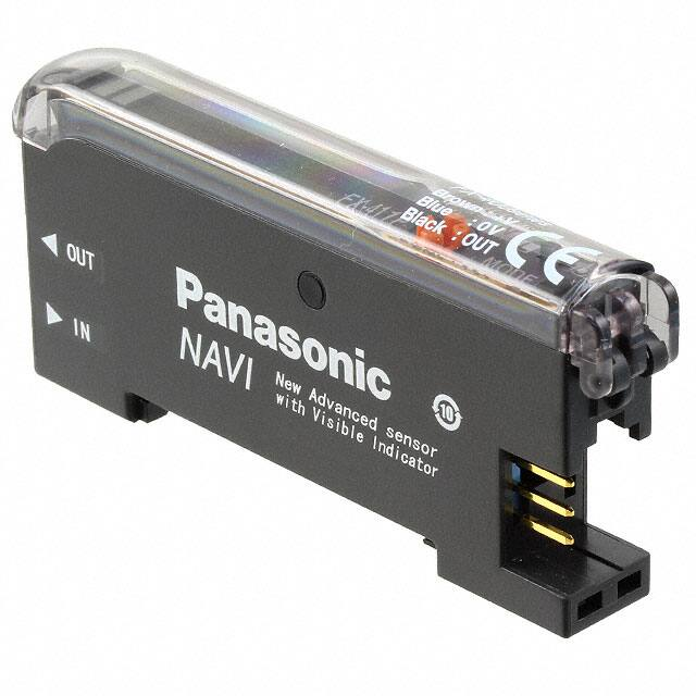


 工商网监
湘ICP备2023018690号
工商网监
湘ICP备2023018690号
