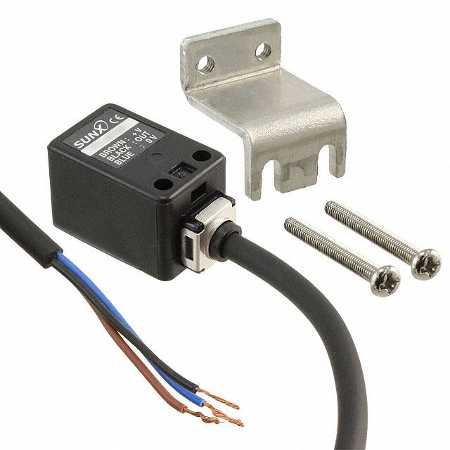
Rectangular-shaped Top Sensing Inductive Proximity Sensor
Amplifier Built-in
Oil resistant Different freq.
type available
GXL
INDUCTIVE
PROXIMITY SENSORS
GL-18H/18HL
Conforming to
EMC Directive
Low price
Different frequency type
Long sensing range
It provides high performance at a low
price.
Two sensors can be mounted close
together because different frequency
types are available.
The long sensing range type,
GL-18HL(B), and its different frequency type, GL-18HLI, can be
mounted 20 mm 0.787 in away from
each other.
GL-18HL� offers a long sensing
range of 12 mm 0.472 in.
(GL-18H�: 5 mm 0.197 in)
(
GX
GX-N
GX-U/FU
GL-18H/18HL
GL-N12
Amplifier Built-in
GL-8/8U
GL-6
High performance
sensing at a low price
)
12 mm
0.472 in
APPLICATIONS
Positioning metal pallet
Detecting aluminum lid
GA-10/GH
Amplifier-separated
Detecting over-run of moving table
718
Ramco Innovations - 1207 Maple Street, West Des Moines IA USA 50265 - 800-280-6933 - www.ramcoinnovations.com
�ORDER GUIDE
Accessory
Sensing range (Note)
Model No.
Maximum operation distance
Standard
Output
Output operation
(
GL-18H
5 mm 0.197 in
Different
frequency
• MS-GL18HL
Sensor mounting
bracket
)
Normally open
GXL
Appearance
(mm in)
Type
GL-18HI
(0 to 4 mm 0 to 0.157 in)
Long sensing
range
28
1.102
18
0.709
GL-18HB
NPN
open-collector
transistor
GL-18HL
12 mm 0.472 in
Different
frequency
Normally closed
Normally open
GL-6
Stable sensing range
18
0.709
GL-18HLI
mm
( 00 toto 10
0.394 in )
GL-18HLB
INDUCTIVE
PROXIMITY SENSORS
GL-18H/18HL
Normally closed
Two M3 (length 25 mm 0.948 in)
pan head screws are attached.
GL-8/8U
Note: The maximum operation distance stands for the maximum distance for which the sensor can detect the standard sensing
object.
The stable sensing range stands for the sensing range for which the sensor can stably detect the standard sensing object
even if there is an ambient temperature drift and/or supply voltage fluctuation.
Type
0 to 4 mm 0 to 0.157 in
0 to 10 mm 0 to 0.394 in
Iron sheet 40�40�t 1 mm 1.575�1.575�t 0.039 in
15 % or less of operation distance
10 to 30 V DC Ripple P-P 10 % or less
Supply voltage
10 mA or less
Current consumption
NPN open-collector transistor
• Maximum sink current: 100 mA
• Applied voltage: 30 V DC or less (between output and 0 V)
• Residual voltage: 1.5 V or less (at 100 mA sink current)
0.4 V or less (at 16 mA sink current)
Output
DC-12 or DC-13
Utilization category
Max. response frequency
Operation indicator
Environmental resistance
Pollution degree
Protection
Ambient temperature
Normally open
Normally closed
Normally open
1 kHz
Normally closed
500 Hz
Red LED (lights up when the output is ON)
3 (Industrial environment)
IP67 (IEC), IP67g (JEM)
�25 to�70 �C �13 to�158 �F, Storage:�25 to�70 �C �13 to�158 �F
Ambient humidity
45 to 85 % RH, Storage: 45 to 85 % RH
EMC
EN 50081-2, EN 50082-2, EN 60947-5-2
Voltage withstandability
GL-18HLB
12 mm 0.472 in�10 %
Iron sheet 25�25�t 1 mm 0.984�0.984�t 0.039 in
Hysteresis
Output operation
GL-18HL
GX-U/FU
Standard sensing object
GL-18HB
5 mm 0.197 in�10 %
1,000 V AC for one min. between all supply terminals connected together and enclosure
Insulation resistance
50 MΩ, or more, with 250 V DC megger between all supply terminals connected together and enclosure
Vibration resistance
10 to 55 Hz frequency, 1.5 mm 0.059 in amplitude in X, Y and Z directions for two hours each
Shock resistance
Sensing range Temperature characteristics
variation
Voltage characteristics
Material
Cable
Cable extension
Weight
Accessory
GX-N
Stable sensing range (Note)
GL-18H
GX
Model No.
Long sensing range
Different frequency
GL-18HLI
1,000 m/s2 acceleration (100 G approx.) in X, Y and Z directions for three times each
Over ambient temperature range�25 to�70 �C �13 to�158 �F: within�10 % of sensing range at 20 �C �68 �F
Within�2 % for�10 % fluctuation of the supply voltage
Enclosure: Polyalylate
0.3 mm2 3-core oil resistant cabtyre cable, 1 m 3.281 ft long
Extension up to total 100 m 328.084 ft is possible with 0.3 mm2, or more, cable.
45 g approx.
MS-GL18HL (Sensor mounting bracket): 1 set
Note: The maximum operation distance stands for the maximum distance for which the sensor can detect the standard sensing object.
The stable sensing range stands for the sensing range for which the sensor can stably detect the standard sensing object even if there is an ambient
temperature drift and/or supply voltage fluctuation.
Ramco Innovations - 1207 Maple Street, West Des Moines IA USA 50265 - 800-280-6933 - www.ramcoinnovations.com
719
Amplifier-separated
GA-10/GH
Item
Max. operation distance (Note)
Standard
Different frequency
GL-18HI
Amplifier Built-in
GL-18H/18HL
GL-N12
SPECIFICATIONS
�INDUCTIVE
PROXIMITY SENSORS
GL-18H/18HL
I/O CIRCUIT AND WIRING DIAGRAMS
GL-18H�
GL-18HL�
I/O circuit diagram
Wiring diagram
Brown
GXL
Color code
Sensor circuit
(Brown)�V
Load
Black
Load
(Black) Output (Note)
Tr
100 mA max.
ZD
�
�
�
�
10 to 30 V DC
Blue
10 to 30 V DC
Internal circuit
Users’ circuit
Note: Please carry out the wiring carefully since protection circuit against
reverse power supply connection is not incorporated.
Note: Further, the output is not incorporated with a short-circuit protection
circuit.
Do not connect it directly to a power supply or a capacitive load.
Symbols ... ZD: Surge absorption zener diode
Tr : NPN output transistor
SENSING CHARACTERISTICS (TYPICAL)
GL-18H�
8
0.315
Setting distance L (mm in)
Standard sensing
object Iron sheet
25�25�t 1 mm
0.984�0.984�t 0.039 in
6
0.236
4
0.157
#
2
0.079
L
0
10
0.394
5
0
5
10
0.197
0.197
0.394
Center
Left
Right
Operating point ?(mm in)
2
0.079
0
Stainless steel
(SUS304)
Brass
Aluminum
10
20
30
0.394
0.787
1.181
Sensing object side
length a (mm in)
40
1.575
10
0.394
5
0.197
0
20
0.787
720
Standard sensing
object Iron sheet
40�40�t 1 mm
1.575�1.575�t 0.039 in
#
L
10
0
10
20
0.394
0.394
0.787
Center
Left
Right
Operating point ?(mm in)
Correlation between sensing object size and sensing range
20
As the sensing object size becomes smaller than
0.787 Sensing object a�a mm a�a in
the standard size (iron sheet 40�40�t 1 mm
t 1 mm
L
t 0.039 in
1.575� 1.575� t 0.039 in), the sensing range
15
shortens as shown in the left figure.
0.591
Sensing range L (mm in)
Setting distance L (mm in)
GX
4
0.157
GL-18HL�
Sensing field
GA-10/GH
Amplifier-separated
Correlation between sensing object size and sensing range
8
As the sensing object size becomes smaller than
0.315 Sensing object a�a mm a�a in
the standard size (iron sheet 25�25�t 1 mm
t 1 mm
L
t 0.039 in
0.984� 0.984� t 0.039 in), the sensing range
6
shortens as shown in the left figure.
0.236
Iron
Sensing range L (mm in)
Sensing field
GX-N
GX-U/FU
GL-18H/18HL
GL-N12
Amplifier Built-in
GL-8/8U
GL-6
(Blue) 0 V
Iron
10
0.394
Stainless steel
(SUS304)
5
0197
Brass
Aluminum
0
20
40
60
0.787
1.575
2.362
Sensing object side
length a (mm in)
80
3.150
Ramco Innovations - 1207 Maple Street, West Des Moines IA USA 50265 - 800-280-6933 - www.ramcoinnovations.com
�Refer to p.1152l for general precautions.
This product is not a safety sensor. Its use is not
intended or designed to protect life and prevent body
injury or property damage from dangerous parts of
machinery. It is a normal object detection sensor.
Mounting
• The tightening torque should
be 0.5 N m or less.
M3 pan head screws or truss
head screw
(Do not uses flat head screws)
• To mount the sensor with a
nut, the thru-hole diameter
should be "3.4 mm "0.134 in.
M3�0.5 mm 0.020 in
tapped holes or "3.4 mm
0.134 in thru-holes
Correction coefficient
Metal
GL-18H�
Metal
B
C
Metal
GL-18HL�
A
5 mm 0.197 in 25 mm 0.984 in
B
20 mm 0.787 in 60 mm 2.362 in
C
0 mm 0.000 in 20 mm 0.787 in (Note)
D
5 mm 0.197 in 30 mm 1.181 in
Note: When the GL-18HL� is mounted
on an insulator, or seated on the
attached aluminum mounting
bracket, the distance ‘C’ can be
zero.
D
D
GL-18H�
GL-18HL�
1
1
Stainless steel
(SUS304)
0.68 approx.
0.65 approx.
Brass
0.45 approx.
0.42 approx.
Aluminum
0.43 approx.
0.41 approx.
Wiring
• Please carry out the wiring carefully since protection
circuit against reverse power supply connection is not
incorporated.
• Further, the output is not incorporated with a short-circuit
protection circuit. Do not connect it directly to a power
supply or a capacitive load.
Others
• Do not use during the initial transient time (50 ms) after
the power supply is switched on.
GL-18HL�
Between ‘I’ Between two ‘I’
type and
types or two
non ‘I’ type non ‘I’ types
E
0 mm (Note 2)
40 mm 1.575 in
20 mm 0.787 in
130 mm 5.118 in
F
20 mm 0.787 in
70 mm 2.756 in
40 mm 1.575 in
200 mm 7.874 in
E
F
GX-N
GL-18H�
Between ‘I’ Between two ‘I’
types or two
type and
non ‘I’ type non ‘I’ types
GX-U/FU
Mutual interference prevention
• When two or more sensors are installed in parallel or face
to face, keep the minimum separation distance specified
below to avoid mutual interference.
Notes: 1) ‘I’ in the model No. specifies the different frequency type.
Notes: 2) Close mounting is possible for up to two sensors.
When mounting three sensors or more, at an equal spacing, in a
row, the minimum value of dimension ‘E’ should be 11 mm 0.433 in.
The CAD data in the dimensions can be downloaded from the SUNX website: http://www.sunx.co.jp/
GX
DIMENSIONS (Unit: mm in)
GL-8/8U
GL-6
Metal
Amplifier Built-in
GL-18H/18HL
GL-N12
One set of two washers
and a nut is used.
Influence of surrounding metal
• When there is a metal near the sensor, keep the minimum
separation distance specified below.
A
Model No.
Iron
mm
• Screws, nuts or washers 10.5
0.413 in
are not supplied. Please
arrange them separately.
Metal
Sensing range
• The sensing range is specified for the standard sensing
object. With a non-ferrous metal, the sensing range is
obtained by multiplying with the correction coefficient
specified below. Further, the sensing range also changes if
the sensing object is plated.
INDUCTIVE
PROXIMITY SENSORS
PRECAUTIONS FOR PROPER USE
GXL
GL-18H/18HL
28
1.102
24.5
0.965
18.8
0.740
Sensing
direction
18
0.709
MS-GL18HL
Sensor
10.5
0.413
4
0.157
3.2
0.126
2-M3�0.5 0.020
2-"3.3 "0.130
mounting holes
10.5
0.413
11
0.433
"4.8 "0.189 cable,
1 m 3.281 ft long
Operation indicator (Red)
18
0.709
Sensor mounting bracket for GL-18HL� (Accessory)
11
0.433
Amplifier-separated
GA-10/GH
GL-18H�
GL-18HL�
10
0.394
17.5
0.689
(6.1)(0.240)
4.5
0.177
10
0.394
Material: Aluminum
Two M3 (length 25 mm 0.984 in)
pan head screws are attached.
11
0.433
20
0.787
(4.5)(0.177)
20
0.787
t2
t 0.079
7
0.276
Ramco Innovations - 1207 Maple Street, West Des Moines IA USA 50265 - 800-280-6933 - www.ramcoinnovations.com
721
�
很抱歉,暂时无法提供与“GL-18H”相匹配的价格&库存,您可以联系我们找货
免费人工找货