817
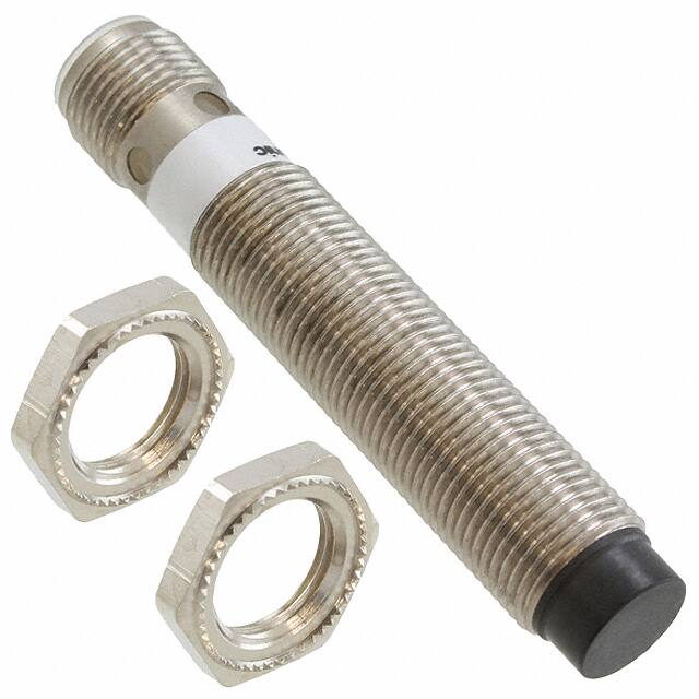
Cylindrical Inductive Proximity Sensor
GX-M SERIES
Related Information
FIBER
SENSORS
■■General terms and conditions.............. F-3
■■Glossary of terms........................P.1576~
Amplifier Built-in
■■Selection guide.............................. P.781~
■■General precautions.................... P.1579~
LASER
SENSORS
PHOTOELECTRIC
SENSORS
Listing
(2 m cable length type only)
MICRO
PHOTOELECTRIC
SENSORS
Features
AREA
SENSORS
SAFETY LIGHT
CURTAINS /
SAFETY COMPONENTS
PRESSURE /
FLOW
SENSORS
INDUCTIVE
PROXIMITY
SENSORS
PARTICULAR
USE SENSORS
SENSOR
OPTIONS
SIMPLE
WIRE-SAVING
UNITS
panasonic.net/id/pidsx/global
WIRE-SAVING
SYSTEMS
• Wide product range
Types: D
� C 3-wire shielded type
DC 3-wire non-shielded type
DC 2-wire standard type
DC 2-wire long range type
Size: M8, M12, M18, M30
Connector: 2
� m (6.56 ft) cable length type
M12 plug-in connector type
M12 pigtailed type (DC 2-wire
M8 type only)
• Strong resistance IP68 (GX-M8□: IP67)
MEASUREMENT
SENSORS
Type
GX-F/H
GXL
GL
GX-M
GX-U/GX-FU/
GX-N
GX
Sensing range (Note 1,2)
Max. operation distance: 2 mm 0.08 in
(Stable sensing range 0 to 1.6 mm 0.06 in)
Max. operation distance: 5 mm 0.20 in
(Stable sensing range 0 to 4 mm 0.16 in)
M30
Max. operation distance: 1.5 mm 0.06 in
(Stable sensing range 0 to 1.2 mm 0.05 in)
Ex.) GX-M12□
Max. operation distance: 10 mm 0.39 in
(Stable sensing range 0 to 8 mm 0.32 in)
Max. operation distance: 7 mm 0.28 in
(Stable sensing range 0 to 5.6 mm 0.22 in)
Max. operation distance: 12 mm 0.47 in
(Stable sensing range 0 to 9.6 mm 0.38 in)
M30
Selection
Guide
Amplifier
Built-in
Amplifierseparated
Other
Products
Non-shielded
UV CURING
SYSTEMS
Shielded
MACHINE VISION
SYSTEMS
Appearance
M8
FA COMPONENTS
DC 3-wire type (2 m cable length type)
M12
ENERGY
MANAGEMENT
SOLUTIONS
M18
HUMAN MACHINE
INTERFACES
Metal embedding
possible
ORDER GUIDE
PLC
M12
LASER
MARKERS
Oil resistant
2-wire type PNP output
type available
available
Large selection
M18
STATIC
CONTROL
DEVICES
Ex.) GX-MK12□
Max. operation distance: 22 mm 0.87 in
(Stable sensing range 0 to 17.6 mm 0.69 in)
Model No.
NPN output
PNP output
Output
operation
GX-M8A
GX-M8A-P
Normally open
GX-M8B
GX-M8B-P
Normally closed
GX-M12A
GX-M12A-P
Normally open
GX-M12B
GX-M12B-P
Normally closed
GX-M18A
GX-M18A-P
Normally open
GX-M18B
GX-M18B-P
Normally closed
GX-M30A
GX-M30A-P
Normally open
GX-M30B
GX-M30B-P
Normally closed
GX-MK12A
GX-MK12A-P Normally open
GX-MK12B
GX-MK12B-P Normally closed
GX-MK18A
GX-MK18A-P Normally open
GX-MK18B
GX-MK18B-P Normally closed
GX-MK30A
GX-MK30A-P Normally open
GX-MK30B
GX-MK30B-P Normally closed
Notes: 1) It is the value in state where the circumference of a detection side has a metal object.
2) �The maximum operation distance stands for the maximum distance for which the sensor can detect the standard sensing object.
The stable sensing range stands for the sensing range for which the sensor can stably detect the standard sensing object even if there is an
ambient temperature drift and/or supply voltage fluctuation.
�Cylindrical Inductive Proximity Sensor
GX-M SERIES
ORDER GUIDE
FIBER
SENSORS
LASER
SENSORS
DC 2-wire type (2 m cable length type)
PHOTOELECTRIC
SENSORS
GX-M8A-U
Normally open
MICRO
PHOTOELECTRIC
SENSORS
GX-M8B-U
Normally closed
GX-M12A-U
Normally open
GX-M12B-U
Normally closed
GX-M18A-U
Normally open
GX-M18B-U
Normally closed
GX-M30A-U
Normally open
GX-M30B-U
Normally closed
GX-ML8A-U
Normally open
GX-ML8B-U
Normally closed
GX-ML12A-U
Normally open
GX-ML12B-U
Normally closed
GX-ML18A-U
Normally open
GX-ML18B-U
Normally closed
GX-ML30A-U
Normally open
GX-ML30B-U
Normally closed
M8
Max. operation distance: 5 mm 0.20 in
(Stable sensing range 0 to 4 mm 0.16 in)
M30
Max. operation distance: 2 mm 0.08 in
(Stable sensing range 0 to 1.6 mm 0.06 in)
Max. operation distance: 10 mm 0.39 in
(Stable sensing range 0 to 8 mm 0.32 in)
M8
M12
Model No.
Max. operation distance: 1.5 mm 0.06 in
(Stable sensing range 0 to 1.2 mm 0.05 in)
Max. operation distance: 2.5 mm 0.10 in
(Stable sensing range 0 to 2 mm 0.08 in)
Ex.) GX-M12□-U
Max. operation distance: 4 mm 0.16 in
(Stable sensing range 0 to 3.2 mm 0.13 in)
M18
M12
Output operation
Sensing range (Note 1,2)
M18
Appearance
Max. operation distance: 8 mm 0.32 in
(Stable sensing range 0 to 6.4 mm 0.25 in)
M30
Long range
Standard
Type
818
Max. operation distance: 15 mm 0.59 in
(Stable sensing range 0 to 12 mm 0.47 in)
Notes: 1) It is the value in state where the circumference of a detection side has a metal object.
2) �The maximum operation distance stands for the maximum distance for which the sensor can detect the standard sensing object.
The stable sensing range stands for the sensing range for which the sensor can stably detect the standard sensing object even if there is an ambient
temperature drift and/or supply voltage fluctuation.
AREA
SENSORS
SAFETY LIGHT
CURTAINS /
SAFETY
COMPONENTS
PRESSURE /
FLOW
SENSORS
INDUCTIVE
PROXIMITY
SENSORS
PARTICULAR
USE
SENSORS
SENSOR
OPTIONS
SIMPLE
WIRE-SAVING
UNITS
WIRE-SAVING
SYSTEMS
MEASUREMENT
SENSORS
STATIC
CONTROL
DEVICES
LASER
MARKERS
PLC
HUMAN
MACHINE
INTERFACES
M12 plug-in connector type (except for GX-M8□-U and GX-ML8□-U)
ENERGY
MANAGEMENT
SOLUTIONS
M12 plug-in connector type is also available.
When ordering this type, suffix “-Z” for the M12 plug-in connector type to the model No.
(e.g.) M12 plug-in connector type of GX-M8A-P is “GX-M8A-P-Z”.
FA
COMPONENTS
MACHINE
VISION
SYSTEMS
UV
CURING
SYSTEMS
M12 pigtailed type (for GX-M8□-U and GX-ML8□-U only)
M12 pigtailed type is also available.
When ordering this type, suffix “-J” for the M12 pigtailed type to the model No.
(e.g.) M12 pigtailed type of GX-M8A-U is “GX-M8A-U-J”.
Selection
Guide
Amplifier
Built-in
Amplifierseparated
Other
Products
Mating cable
• Mating cable
For M12 plug-in
connector type
Type
Straight
Elbow
Model No.
Description
CN-24C-C2
Length: 2 m 6.56 ft
CN-24C-C5
Length: 5 m 16.40 ft
Clamping ring :
ø14mm 0.55 in
CN-24CL-C2
Length: 2 m 6.56 ft
CN-24CL-C5
Length: 5 m 16.40 ft
Cable outer :
ø5.3mm 0.21 in
• Straight type
• Elbow type
GX-F/H
GXL
GL
GX-M
GX-U/GX-FU/
GX-N
GX
�819
Cylindrical Inductive Proximity Sensor
SPECIFICATIONS
FIBER
SENSORS
LASER
SENSORS
DC 3-wire type
PHOTOELECTRIC
SENSORS
AREA
SENSORS
SAFETY LIGHT
CURTAINS /
SAFETY
COMPONENTS
PRESSURE /
FLOW
SENSORS
INDUCTIVE
PROXIMITY
SENSORS
PARTICULAR
USE
SENSORS
SENSOR
OPTIONS
Item
Normally open
GX-M12A□
GX-M18A□
GX-M30A□
GX-MK12A□
GX-MK18A□
GX-MK30A□
Normally closed
GX-M8B□
GX-M12B□
GX-M18B□
GX-M30B□
GX-MK12B□
GX-MK18B□
GX-MK30B□
CE marking directive compliance
Stable sensing range (Note 2,3)
Standard sensing object
ENERGY
MANAGEMENT
SOLUTIONS
FA
COMPONENTS
MACHINE
VISION
SYSTEMS
UV
CURING
SYSTEMS
5 mm 0.20 in ±10 %
10 mm 0.39 in ±10 %
7 mm 0.28 in ±10 %
12 mm 0.47 in ±10 %
22 mm 0.87 in ±10 %
0 to 1.2 mm
0 to 0.05 in
0 to 1.6 mm
0 to 0.06 in
0 to 4 mm
0 to 0.16 in
0 to 8 mm
0 to 0.32 in
0 to 5.6 mm
0 to 0.22 in
0 to 9.6 mm
0 to 0.38 in
0 to 17.6 mm
0 to 0.69 in
Iron sheet 8 × 8 × t 1 mm
0.32 × 0.32 × t 0.04 in
Iron sheet 12 × 12 × t 1 mm
0.47 × 0.47 × t 0.04 in
Iron sheet 18 × 18 × t 1 mm
0.71 × 0.71 × t 0.04 in
Iron sheet 30 × 30 × t 1 mm
1.18 × 1.18 × t 0.04 in
Iron sheet 24 × 24 × t 1 mm
0.94 × 0.94 × t 0.04 in
Iron sheet 24 × 24 × t 1 mm
0.94 ×0.94 × t 0.04 in
Iron sheet 45 × 45 × t 1 mm
1.77 × 1.77 × t 0.04 in
15 % or less of operation distance (with standard sensing object)
Repeatability (Note 2)
Along sensing axis: 5 % or less of operation distance
Supply voltage
12 to 24 V DC ±10 % Ripple P-P 10 % or less
Current consumption
10 mA or less
NPN open-collector transistor
• Maximum sink current 200 mA
• Applied voltage: 24 V DC or less (between output and 0 V)
• Residual voltage 2 V or less
Output
Incorporated
Short-circuit protection
Max. response frequency
5 kHz
5 kHz
Operation indicator
IP67 (IEC)
Voltage withstandability
500 V AC for one min. between all supply terminals connected together and enclosure
10 to 55 Hz frequency, 0.5 mm 0.02 in double amplitude in X, Y and Z directions for 1.5 hours each
294 m/s2 acceleration (30 G approx.) in X, Y and Z directions three times each
Shock resistance
Within ±10 % fluctuation of sensing range at +23 °C +73 °F and rated voltage in the range of
allowable temperature and supply voltage
Enclosure: Brass (Nickel plated), Sensing part: PPS
Selection
Guide
Cable extension
Amplifier
Built-in
Net weight
(Note 4)
GX-F/H
GXL
GL
GX-M
GX-U/GX-FU/
GX-N
GX
0.5 kHz
50 % RH or less (at +70 °C +158 °F)
Material
Other
Products
1 kHz
–25 to +70 °C –13 to +158 °F, Storage: –40 to +85 °C –40 to +185 °F
0.44 mm2 (0.15 mm2 for GX-M8□) 3-core cabtyre cable, 2 m 6.56 ft long
Cable (except for M12 plug-in connector type)
Amplifierseparated
2.5 kHz
IP69K (DIN), IP68 (IEC) (2 m cable length type only) , IP67 (IEC) (M12 plug-in connector type only)
Ambient humidity
Sensing range variation
(Note 2)
1 kHz
3 (industrial enviroment)
Ambient temperature
Vibration resistance
2 kHz
Yellow LED (lights up when the output is ON)
Pollution degree
Protection
PNP open-collector transistor
• Maximum source current 200 mA
• Applied voltage: 24 V DC or less (between output and + V)
• Residual voltage 2 V or less
DC-12 or DC-13
Utilization category
Environmental resistance
HUMAN
MACHINE
INTERFACES
2 mm 0.08 in ±10 %
Hysteresis (Note 2)
STATIC
CONTROL
DEVICES
PLC
EMC Directive, RoHS Directive
Max. operation distance (Note 2,3) 1.5 mm 0.06 in ±10 %
MEASUREMENT
SENSORS
LASER
MARKERS
Non-shielded type
GX-M8A□
SIMPLE
WIRE-SAVING
UNITS
WIRE-SAVING
SYSTEMS
Shielded type
Type
Model No.
MICRO
PHOTOELECTRIC
SENSORS
GX-M SERIES
Extension up to total 10 m 32.80 ft is possible with 0.34 mm2, or more, cable.
2 m cable length type
40 g approx.
70 g approx.
90 g approx.
150 g approx.
75 g approx.
100 g approx.
180 g approx.
M12 plug-in connector type
15 g approx.
20 g approx.
45 g approx.
110 g approx.
25 g approx.
55 g approx.
140 g approx.
Accessories
Nut: 2 pcs.
Notes: 1) Where measurement conditions have not been specified precisely, the conditions used were an ambient temperature of +23 °C +73.4 °F.
2) It is the value in state where the circumference of a detection side has a metal object.
3) The maximum operation distance stands for the maximum distance for which the sensor can detect the standard sensing object.
The stable sensing range stands for the sensing range for which the sensor can stably detect the standard sensing object even if there is an ambient
temperature drift and/or supply voltage fluctuation.
4) The weight includes the weight of two nuts.
�Cylindrical Inductive Proximity Sensor
GX-M SERIES
SPECIFICATIONS
FIBER
SENSORS
LASER
SENSORS
DC 2-wire type
Standard type
Model No.
Type
Item
Long range type
Normally open
GX-M8A-U(-J) GX-M12A-U(-Z) GX-M18A-U(-Z) GX-M30A-U(-Z) GX-ML8A-U(-J) GX-ML12A-U(-Z) GX-ML18A-U(-Z) GX-ML30A-U(-Z)
Normally closed
GX-M8B-U(-J) GX-M12B-U(-Z) GX-M18B-U(-Z) GX-M30B-U(-Z) GX-ML8B-U(-J) GX-ML12B-U(-Z) GX-ML18B-U(-Z) GX-ML30B-U(-Z)
CE marking directive compliance
EMC Directive, RoHS Directive
Max. operation distance (Note 2,3) 1.5 mm 0.06 in ±10 % 2 mm 0.08 in ±10 %
Stable sensing range (Note 2,3)
Standard sensing object
5 mm 0.20 in ±10 % 10 mm 0.39 in ±10 % 2.5 mm 0.10 in ±10 % 4 mm 0.16 in ±10 %
0 to 4 mm
0 to 0.09 in
0 to 8 mm
0 to 0.22 in
0 to 2 mm
0 to 0.08 in
0 to 3.2 mm
0 to 0.13 in
0 to 6.4 mm
0 to 0.25 in
0 to 12 mm
0 to 0.47 in
Iron sheet 8 × 8 × t 1 mm
0.32 × 0.32 × t 0.04 in
Iron sheet 12 × 12 × t 1 mm
0.47 × 0.47 × t 0.04 in
Iron sheet 18 × 18 × t 1mm
0.71 × 0.71 × t 0.04 in
Iron sheet 30 × 30 × t 1 mm
1.18 × 1.18 × t 0.04 in
Iron sheet 8 × 8 × t 1 mm
0.32 × 0.32 × t 0.04 in
Iron sheet 12 × 12 × t 1 mm
0.47 × 0.47 × t 0.04 in
Iron sheet 18 × 18 × t 1 mm
0.71 × 0.71 × t 0.04 in
Iron sheet 30 × 30 × t 1 mm
1.18 × 1.18 × t 0.04 in
15 % or less of operation distance (with standard sensing object)
Supply voltage
12 to 24 V DC ±10 % Ripple P-P 10 % or less
Max. response frequency
1 kHz
1.2 kHz
Operation indicator
1.3 kHz
1.3 kHz
1.5 kHz
0.8 kHz
IP67 (IEC)
IP69K (DIN), IP68 (IEC) (2 m cable length type only) , IP67 (IEC) (M12 plug-in connector type only)
–25 to +70 °C –13 to +158 °F, Storage: –40 to +85 °C –40 to +185 °F
Ambient humidity
500 V AC for one min. between all supply terminals connected together and enclosure
Vibration resistance
10 to 55 Hz frequency, 0.5 mm 0.02 in double amplitude in X, Y and Z directions for 1.5 hours each
294 m/s2 acceleration (30 G approx.) in X, Y and Z directions three times each
Shock resistance
FA
COMPONENTS
UV
CURING
SYSTEMS
Enclosure: Brass (Nickel plated), Sensing part: PPS
0.44 mm2 [0.15 mm2 for GX-M(L)8□-U] 2-core cabtyre cable, 2 m 6.56 ft long
Cable (except for M12 plug-in connector type)
Cable extension
Extension up to total 10 m 32.80 ft is possible with 0.34 mm2, or more, cable.
2 m cable length type
40 g approx.
70 g approx.
90 g approx.
150 g approx.
40 g approx.
70 g approx.
90 g approx.
150 g approx.
M12 pigtailed(-J type) /
M12 plug-in connector type
20 g approx.
20 g approx.
45 g approx.
110 g approx.
20 g approx.
20 g approx.
45 g approx.
110 g approx.
Accessories
ENERGY
MANAGEMENT
SOLUTIONS
MACHINE
VISION
SYSTEMS
Within ±10 % fluctuation of sensing range at +23 °C +73 °F and rated voltage in the range of
allowable temperature and supply voltage
Material
PLC
HUMAN
MACHINE
INTERFACES
50 % RH or less (at +70 °C +158 °F)
Voltage withstandability
STATIC
CONTROL
DEVICES
LASER
MARKERS
3 (Industrial environment)
Ambient temperature
Sensing range variation
(Note 2)
1.1 kHz
Yellow LED (lights up when the output is ON)
Pollution degree
Protection
MEASUREMENT
SENSORS
Incorporated
1 kHz
INDUCTIVE
PROXIMITY
SENSORS
WIRE-SAVING
SYSTEMS
DC-12 or DC-13
Utilization category
PRESSURE /
FLOW
SENSORS
SIMPLE
WIRE-SAVING
UNITS
Non-contact DC 2-wire type
• Load current: 1.5 to 100 mA
• Residual voltage: 4.2 V or less (Note 5)
Short-circuit protection
SAFETY LIGHT
CURTAINS /
SAFETY
COMPONENTS
SENSOR
OPTIONS
0.5 mA or less
Output
MICRO
PHOTOELECTRIC
SENSORS
PARTICULAR
USE
SENSORS
Along sensing axis: 5 % or less of operation distance
Current consumption (Note 4)
Environmental resistance
8 mm 0.32 in ±10 % 15 mm 0.59 in ±10 %
0 to 1.6 mm
0 to 0.06 in
Repeatability (Note 2)
PHOTOELECTRIC
SENSORS
AREA
SENSORS
0 to 1.2 mm
0 to 0.05 in
Hysteresis (Note 2)
Net weight
(Note 6)
820
Nut: 2 pcs.
Notes: 1) Where measurement conditions have not been specified precisely, the conditions used were an ambient temperature of +23 °C +73.4 °F.
2) It is the value in state where the circumference of a detection side has a metal object.
3) The maximum operation distance stands for the maximum distance for which the sensor can detect the standard sensing object.
The stable sensing range stands for the sensing range for which the sensor can stably detect the standard sensing object even if there is an ambient
temperature drift and/or supply voltage fluctuation.
4) It is the leakage current when the output is in the OFF state.
5) When the cable is extended, the residual voltage becomes larger.
6) The weight includes the weight of two nuts.
Selection
Guide
Amplifier
Built-in
Amplifierseparated
Other
Products
GX-F/H
GXL
GL
GX-M
GX-U/GX-FU/
GX-N
GX
�821
FIBER
SENSORS
LASER
SENSORS
GX-M SERIES
Cylindrical Inductive Proximity Sensor
WIRING DIAGRAMS
DC 3-wire type
PHOTOELECTRIC
SENSORS
Wiring diagrams
MICRO
PHOTOELECTRIC
SENSORS
NPN output type
PNP output type
(Brown) +V
AREA
SENSORS
(Brown) +V
Load
SAFETY LIGHT
CURTAINS /
SAFETY
COMPONENTS
+
(Black) Output
–
(Black) Output
12 to 24V DC ±10 %
–
Load
PRESSURE /
FLOW
SENSORS
(Blue) 0 V
(Blue) 0 V
INDUCTIVE
PROXIMITY
SENSORS
PARTICULAR
USE
SENSORS
SENSOR
OPTIONS
SIMPLE
WIRE-SAVING
UNITS
Connector pin position
M12 connector
4
3
1
2
• Normally Open
1 : +V
2 : Not connected
3:0V
4 : Output
• Normally Closed
1 : +V
2 : Output
3:0V
4 : Not connected
WIRE-SAVING
SYSTEMS
MEASUREMENT
SENSORS
STATIC
CONTROL
DEVICES
LASER
MARKERS
DC 2-wire type
Wiring diagrams
(Brown) +V
PLC
–
ENERGY
MANAGEMENT
SOLUTIONS
FA
COMPONENTS
MACHINE
VISION
SYSTEMS
UV
CURING
SYSTEMS
Selection
Guide
Amplifier
Built-in
Amplifierseparated
Other
Products
GX-F/H
GXL
GL
GX-M
GX-U/GX-FU/
GX-N
GX
Load
+
HUMAN
MACHINE
INTERFACES
(Blue) 0 V
12 to 24V DC ±10 %
Load
Connector pin position
M12 connector
4
3
1
2
• Normally Open
• Normally Closed
1 : +V
(except for GX-M8□-U-J and GX-ML8□-U-J)
1 : Not connected
2 : Not connected
3 : +V
4:0V
• Normally Open
(GX-M8□-U-J and GX-ML8□-U-J only)
1 : +V
2 : Not connected
3 : Not connected
4:0V
+
2:0V
3 : Not connected
4 : Not connected
12 to 24V DC ±10 %
�Cylindrical Inductive Proximity Sensor
PRECAUTIONS FOR PROPER USE
GX-M SERIES
822
Refer to p.1579~ for general precautions.
• Never use this product as a sensing device
for personnel protection.
• In case of using sensing devices for
personnel protection, use products which
meet laws and standards, such as OSHA,
ANSI or IEC etc., for personnel protection
applicable in each region or country.
LASER
SENSORS
Embedding of the sensor in metal
• �Sensing range may decrease if the
sensor is completely embedded in
metal. Especially for the non-shielded
type, keep the minimum distance
specified in the right table.
Sensor
B
C
size (mm in) (mm in)
%
Mounting
• The tightening torque should be under the value given
below.
&
M12
12
0.47
12
0.47
M18
18
0.71
18
0.71
M30
30
1.18
30
1.18
Note: �With the non-shielded type, the sensing
range may vary depending on the
position of the nuts.
0HWDO�
• �When two or more sensors are installed in parallel or face
to face, keep the minimum separation distance specified
below to avoid mutual interference.
Face to face mounting
Model No.
GX-M□
GX-M(L)8□-U-J
Sensor
Connector
(Note)
M8
5 N·m
2 N·m
M12
6 N·m
2 N·m
M18
15 N·m
2 N·m
M30
40 N·m
2 N·m
M8
5 N·m
1.5 N·m
Note: Connector is equipped with -Z type or -J type.
• As metal around the sensor may affect the sensing
performance, pay attention to the following points.
Background metal
• The surrounding metal will affect the sensing performance.
Keep the minimum distance specified in the table below.
A
A (mm in)
M8
M12
M18
M30
3
0.12
4
0.16
10
0.39
20
0.79
-
21
0.83
36
1.42
66
2.60
DC 2-wire standard type
4.5
0.18
6
0.23
15
0.59
30
1.18
DC 2-wire long range type
8
0.32
12
0.47
25
0.98
45
1.77
DC 3-wire non-shielded type
DC 3-wire
shielded type
D (mm in)
M8
M12 M18 M30
E (mm in)
M8
M12 M18 M30
18
24
60 120
3
4
10
20
0.71 0.94 2.36 4.72 0.12 0.16 0.39 0.77
AREA
SENSORS
SAFETY LIGHT
CURTAINS /
SAFETY
COMPONENTS
PRESSURE /
FLOW
SENSORS
INDUCTIVE
PROXIMITY
SENSORS
SENSOR
OPTIONS
SIMPLE
WIRE-SAVING
UNITS
WIRE-SAVING
SYSTEMS
STATIC
CONTROL
DEVICES
LASER
MARKERS
PLC
48
72 120
1.89 2.83 4.72
HUMAN
MACHINE
INTERFACES
18
24
60 120
3
4
10
20
0.71 0.94 2.36 4.72 0.12 0.16 0.39 0.77
ENERGY
MANAGEMENT
SOLUTIONS
50 100 180
5
8
16
30
DC 2-wire long 30
1.18 1.97 3.93 7.09 0.20 0.32 0.63 1.18
range type
FA
COMPONENTS
DC 3-wire
non-shielded type
-
84 144 264
3.30 5.67 10.39
Wiring
Influence of surrounding metal
DC 3-wire shielded type
Type
MICRO
PHOTOELECTRIC
SENSORS
MEASUREMENT
SENSORS
E
DC 2-wire
standard type
Distance from surrounding metal
Type
Parallel mounting
D
Sensor size
PHOTOELECTRIC
SENSORS
PARTICULAR
USE
SENSORS
Mutual interference
Tightening torque
FIBER
SENSORS
• Make sure that the power supply is off while wiring.
• Verify that the supply voltage variation is within the rating.
• If power is supplied from a commercial switching regulator,
ensure that the frame ground (F.G.) terminal of the power
supply is connected to an actual ground.
• Ensure that an isolation transformer is utilized for the DC
power supply. If an autotransformer is utilized, the main
body or power supply may be damaged.
• If the used power supply generates a surge, connect a
surge absorber to the power supply to absorb the surge.
• In case noise generating equipment (switching regulator,
inverter motor, etc.) is used in the vicinity of this product,
connect the frame ground (F.G.) terminal of the equipment
to an actual ground.
• Do not run the wires together with high-voltage lines or
power lines or put them in the same raceway. This can
cause malfunction due to induction.
• Damage or burnout may result in case of short circuit of
load or miswiring.
• Make a cable length as short as possible to lessen noise
pickup.
MACHINE
VISION
SYSTEMS
UV
CURING
SYSTEMS
Selection
Guide
Amplifier
Built-in
Amplifierseparated
Other
Products
GX-F/H
GXL
GL
GX-M
GX-U/GX-FU/
GX-N
GX
�823
FIBER
SENSORS
LASER
SENSORS
PHOTOELECTRIC
SENSORS
MICRO
PHOTOELECTRIC
SENSORS
AREA
SENSORS
SAFETY LIGHT
CURTAINS /
SAFETY
COMPONENTS
PRESSURE /
FLOW
SENSORS
INDUCTIVE
PROXIMITY
SENSORS
PARTICULAR
USE
SENSORS
SENSOR
OPTIONS
SIMPLE
WIRE-SAVING
UNITS
WIRE-SAVING
SYSTEMS
Cylindrical Inductive Proximity Sensor
PRECAUTIONS FOR PROPER USE
• Our products have been developed / produced for
industrial use only.
• Avoid using a product where there is excessive vapor,
dust or corrosive gas, or in a place where it could be
exposed directly to water or chemicals.
• Take care that the sensor does not come in direct contact
with water, oil, grease or organic solvents, such as,
thinner, etc.
• Do not use in an environment containing inflammable or
explosive gases.
• Never disassemble or modify the product.
DIMENSIONS (Unit: mm in)
Sensors
b
a
/('
HUMAN
MACHINE
INTERFACES
E
ENERGY
MANAGEMENT
SOLUTIONS
D
FA
COMPONENTS
LED
GX-F/H
GXL
GL
GX-M
GX-U/GX-FU/
GX-N
GX
b
a
b
GX-M8□
33 1.30
25 0.98
45 1.77
24 0.94
M12
GX-M12□
35 1.38
25 0.98
50 1.97
30 1.18
M18
GX-M18□
39 1.54
28 1.10
50 1.97
28 1.10
M30
GX-M30□
43 1.69
32 1.26
55 2.17
32 1.26
Sensors
2 m cable length type (mm in)
Non-shielded type
a
b
c
a
b
M12 plug-in connector type (mm in)
c
M12
GX-MK12□
55 2.17
42 1.65
5 0.20
66 2.60
42 1.65
5 0.20
M18
GX-MK18□
60 2.36
44 1.73
8 0.32
72 2.83
44 1.73
8 0.32
M30
GX-MK30□
63 2.48
41 1.61
13 0.51
74 2.91
41 1.61
13 0.51
2 m cable length type (mm in)
Standard type, Long range type
a
Other
Products
a
M8
Sensors
b
Amplifierseparated
F
M12 plug-in connector type (mm in)
DC 2-wire type
UV
CURING
SYSTEMS
Amplifier
Built-in
2 m cable length type (mm in)
Shielded type
LASER
MARKERS
Selection
Guide
The CAD data can be downloaded from our website.
DC 3-wire type
LED
STATIC
CONTROL
DEVICES
MACHINE
VISION
SYSTEMS
Refer to p.1579~ for general precautions.
Others
MEASUREMENT
SENSORS
PLC
GX-M SERIES
M12 plug-in connector type (mm in)
(M8 size: M12 pigtailed type)
a
b
a
b
M8
GX-M(L)8□-U (-J)
33 1.30
25 0.98
-
24 0.94
M12
GX-M(L)12□-U (-Z)
35 1.38
25 0.98
50 1.97
30 1.18
M18
GX-M(L)18□-U (-Z)
39 1.54
28 1.10
50 1.97
28 1.10
M30
GX-M(L)30□-U (-Z)
43 1.69
32 1.26
55 2.17
32 1.26
�824
MEMO
�


 工商网监
湘ICP备2023018690号
工商网监
湘ICP备2023018690号
