801
DC 2-wire type Micro-size Inductive Proximity Sensor
GXL SERIES
FIBER
SENSORS
Related Information
■■General terms and conditions.............. F-3
■■Glossary of terms........................ P.1576~
Amplifier Built-in
■■Selection guide.............................. P.781~
■■General precautions.................... P.1579~
LASER
SENSORS
PHOTOELECTRIC
SENSORS
MICRO
PHOTOELECTRIC
SENSORS
AREA
SENSORS
SAFETY LIGHT
CURTAINS /
SAFETY COMPONENTS
PRESSURE /
FLOW
SENSORS
INDUCTIVE
PROXIMITY
SENSORS
PARTICULAR
USE SENSORS
SENSOR
OPTIONS
SIMPLE
WIRE-SAVING
UNITS
WIRE-SAVING
SYSTEMS
MEASUREMENT
SENSORS
panasonic.net/id/pidsx/global
STATIC
CONTROL
DEVICES
LASER
MARKERS
PLC
HUMAN MACHINE
INTERFACES
ENERGY
MANAGEMENT
SOLUTIONS
FA COMPONENTS
MACHINE VISION
SYSTEMS
GX-F/H
GXL
GL
GX-M
GX-U/GX-FU/
GX-N
GX
Bending-resistant Different freq.
cable type available type available
High performance in micro-size design
BASIC PERFORMANCE
Versatile mounting
Reduced wiring operation
Since the sensor is fingertip size, it can be mounted in
a tight space.
The wiring cost of the DC 2-wire type is 2/3 that of a
conventional model.
Besides, the possibility of miswiring is reduced.
Particularly convenient when many sensors are used.
UV CURING
SYSTEMS
Selection
Guide
Amplifier
Built-in
Amplifierseparated
Other
Products
2-wire type Oil resistant
available
Wiring of the 3-wire type is
cumbersome.
Wiring of the 2-wire type is
simple and neat.
ENVIRONMENTAL RESISTANCE
Others
Bending-resistant cable type
Cost performance
The bending durability of its cable is ten times that of the
conventional model. The sensor can be mounted on a
moving table or a robot arm.
Achieve high performance at an affordable price.
�DC 2-wire type Micro-size Inductive Proximity Sensor
GXL SERIES
APPLICATIONS
802
FIBER
SENSORS
Detecting wafer frame
Wafer
Detecting aluminum pallet
Code reading
LASER
SENSORS
PHOTOELECTRIC
SENSORS
Wafer frame
MICRO
PHOTOELECTRIC
SENSORS
AREA
SENSORS
SAFETY LIGHT
CURTAINS /
SAFETY
COMPONENTS
PRESSURE /
FLOW
SENSORS
INDUCTIVE
PROXIMITY
SENSORS
PARTICULAR
USE
SENSORS
ORDER GUIDE
SENSOR
OPTIONS
GXL-8 type
Front sensing
Top sensing
DC 2-wire
Type
Appearance (mm in)
Sensing range
(Note 1)
Model No.
(Note 2)
SIMPLE
WIRE-SAVING
UNITS
Output
GXL-8FU
7.4
0.291
8
0.315
20
0.787
Maximum
operation
distance
2.5 mm 0.098 in
(0 to 1.8 mm) (0 to 0.071 in)
8
0.315
8
0.315
23
0.906
Stable sensing range
Normally open
GXL-8FUI
GXL-8HU
WIRE-SAVING
SYSTEMS
MEASUREMENT
SENSORS
STATIC
CONTROL
DEVICES
GXL-8FUB
GXL-8FUIB
Output operation
Normally closed
Non-contact DC 2- wire type
Normally open
GXL-8HUI
LASER
MARKERS
PLC
HUMAN
MACHINE
INTERFACES
GXL-8HUB
Normally closed
GXL-8HUIB
Notes: 1) The maximum operation distance stands for the maximum distance for which the sensor can detect the standard sensing object.
The stable sensing range stands for the sensing range for which the sensor can stably detect the standard sensing object even if there is an ambient
temperature drift and/or supply voltage fluctuation.
2) “ I ” in the model No. indicates a different frequency type.
ENERGY
MANAGEMENT
SOLUTIONS
FA
COMPONENTS
MACHINE
VISION
SYSTEMS
UV
CURING
SYSTEMS
GXL-15 (Standard) type
Front sensing
Top sensing
DC 2-wire
Type
Appearance (mm in)
Sensing range
(Note 1)
Model No.
(Note 2)
Output
GXL-15FU
8
0.315
15
0.591
32
1.260
Maximum
operation
distance
5 mm 0.197 in
(0 to 4 mm) (0 to 0.157 in)
15
0.591
15
0.591
30
1.181
Stable sensing range
Normally open
GXL-15FUI
GXL-15HU
GXL-15HUI
GXL-15HUB
GXL-15HUIB
Selection
Guide
Amplifier
Built-in
Amplifierseparated
Other
Products
GXL-15FUB
GXL-15FUIB
Output operation
Normally closed
Non-contact DC 2- wire type
GX-F/H
Normally open
GXL
GL
Normally closed
Notes: 1) The maximum operation distance stands for the maximum distance for which the sensor can detect the standard sensing object.
The stable sensing range stands for the sensing range for which the sensor can stably detect the standard sensing object even if there is an ambient
temperature drift and/or supply voltage fluctuation.
2) “ I ” in the model No. indicates a different frequency type.
GX-M
GX-U/GX-FU/
GX-N
GX
�803
DC 2-wire type Micro-size Inductive Proximity Sensor
ORDER GUIDE
FIBER
SENSORS
GXL-15 (Long sensing range) type ··· For mounting on non-magnetic material (Note 3)
Type
MICRO
PHOTOELECTRIC
SENSORS
SAFETY LIGHT
CURTAINS /
SAFETY
COMPONENTS
PRESSURE /
FLOW
SENSORS
DC 2-wire
AREA
SENSORS
INDUCTIVE
PROXIMITY
SENSORS
PARTICULAR
USE
SENSORS
SENSOR
OPTIONS
SIMPLE
WIRE-SAVING
UNITS
WIRE-SAVING
SYSTEMS
MEASUREMENT
SENSORS
STATIC
CONTROL
DEVICES
LASER
MARKERS
Front sensing
PHOTOELECTRIC
SENSORS
Top sensing
LASER
SENSORS
GXL SERIES
Appearance (mm in)
Sensing range
(Note 1)
Model No.
(Note 2)
Output
Output operation
GXL-15FLU
8
0.315
15
0.591
32
1.260
Maximum
operation
distance
8 mm 0.315 in
(0 to 6.4 mm) (0 to 0.252 in)
15
0.591
15
0.591
30
1.181
Stable sensing range
Normally open
GXL-15FLUI
GXL-15FLUB
GXL-15FLUIB
GXL-15HLU
Normally closed
Non-contact DC 2- wire type
GXL-15HLUI
GXL-15HLUB
GXL-15HLUIB
Normally open
Normally closed
Notes: 1) The maximum operation distance stands for the maximum distance for which the sensor can detect the standard sensing object.
The stable sensing range stands for the sensing range for which the sensor can stably detect the standard sensing object even if there is an ambient
temperature drift and/or supply voltage fluctuation.
2) “ I ” in the model No. indicates a different frequency type.
Aluminum sheet
3) To mount the long sensing range GXL-15 type on a magnetic body, such as iron, the enclosed aluminum sheet, or any
other aluminum sheet having a minimum size of 30 × 39.5 × t 0.3 mm 1.181 × 1.555 × t 0.012 in
(GXL-15HLU type: 30 × 30 × t 0.3 mm 1.181 × 1.181 × t 0.012 in), should be inserted between the sensor and the
magnetic body.
However, it is not necessary to use the aluminum sheet when mounting on a non-magnetic body, such as, aluminum
or an insulator.
Bending-resistant cable type and 5 m 16.404 ft cable length type
Bending-resistant cable type and 5 m 16.404 ft cable length type (standard: 1 m 3.281 ft) are also available.
HUMAN
MACHINE
INTERFACES
ENERGY
MANAGEMENT
SOLUTIONS
• Table of Model Nos.
Type
FA
COMPONENTS
MACHINE
VISION
SYSTEMS
Selection
Guide
Amplifier
Built-in
Amplifierseparated
Other
Products
GX-F/H
GXL
GL
GX-M
GX-U/GX-FU/
GX-N
GX
DC 2-wire
UV
CURING
SYSTEMS
Top sensing Front sensing Top sensing Front sensing Top sensing Front sensing
PLC
Standard
GXL-8FU
GXL-8FUI
GXL-8FUB
GXL-8FUIB
GXL-8HU
GXL-8HUI
GXL-8HUB
GXL-8HUIB
GXL-15FU
GXL-15FUI
GXL-15FUB
GXL-15FUIB
GXL-15HU
GXL-15HUI
GXL-15HUB
GXL-15HUIB
GXL-15FLU
GXL-15FLUI
GXL-15FLUB
GXL-15FLUIB
GXL-15HLU
GXL-15HLUI
GXL-15HLUB
GXL-15HLUIB
Bending-resistant cable type
GXL-8FU-R
GXL-8FUI-R
GXL-8FUB-R
GXL-8FUIB-R
GXL-8HU-R
GXL-8HUI-R
GXL-8HUB-R
GXL-8HUIB-R
GXL-15FU-R
GXL-15FUI-R
GXL-15FUB-R
GXL-15FUIB-R
GXL-15HU-R
GXL-15HUI-R
GXL-15HUB-R
GXL-15HUIB-R
GXL-15FLU-R
GXL-15FLUI-R
GXL-15FLUB-R
GXL-15FLUIB-R
GXL-15HLU-R
GXL-15HLUI-R
GXL-15HLUB-R
GXL-15HLUIB-R
5 m 16.404 ft cable length type
GXL-8FU-C5
GXL-8FUI-C5
GXL-8FUB-C5
GXL-8FUIB-C5
GXL-8HU-C5
GXL-8HUI-C5
GXL-8HUB-C5
GXL-8HUIB-C5
GXL-15FU-C5
GXL-15FUI-C5
GXL-15FUB-C5
GXL-15FUIB-C5
GXL-15HU-C5
GXL-15HUI-C5
GXL-15HUB-C5
GXL-15HUIB-C5
GXL-15FLU-C5
GXL-15FLUI-C5
GXL-15FLUB-C5
GXL-15FLUIB-C5
GXL-15HLU-C5
GXL-15HLUI-C5
GXL-15HLUB-C5
GXL-15HLUIB-C5
Bending-resistant cable of
5 m 16.404 ft cable length type
GXL-8FU-R-C5
GXL-8FUI-R-C5
GXL-8FUB-R-C5
GXL-8FUIB-R-C5
GXL-8HU-R-C5
GXL-8HUI-R-C5
GXL-8HUB-R-C5
GXL-8HUIB-R-C5
GXL-15FU-R-C5
GXL-15FUI-R-C5
GXL-15FUB-R-C5
GXL-15FUIB-R-C5
GXL-15HU-R-C5
GXL-15HUI-R-C5
GXL-15HUB-R-C5
GXL-15HUIB-R-C5
GXL-15FLU-R-C5
GXL-15FLUI-R-C5
GXL-15FLUB-R-C5
GXL-15FLUIB-R-C5
GXL-15HLU-R-C5
GXL-15HLUI-R-C5
GXL-15HLUB-R-C5
GXL-15HLUIB-R-C5
�DC 2-wire type Micro-size Inductive Proximity Sensor
GXL SERIES
ORDER GUIDE
804
FIBER
SENSORS
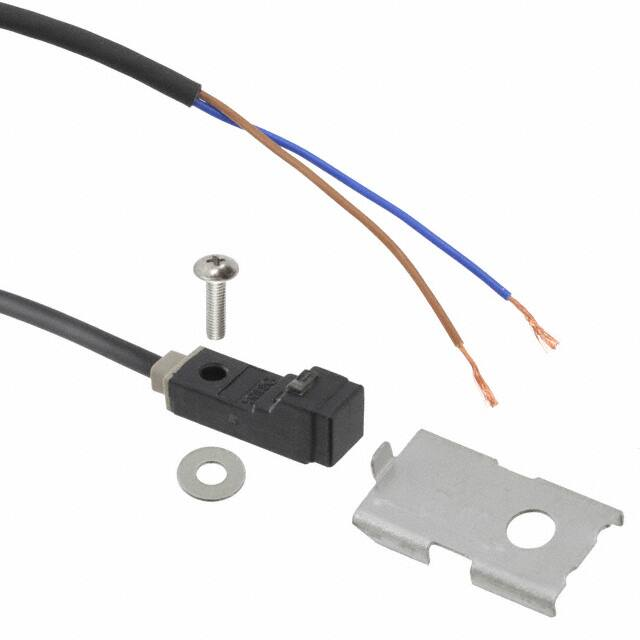
Accessories
• MS-GXL8-4 (Sensor mounting bracket for GXL-8FU, GXL-8HU type)
• MS-A15F (Aluminum sheet for GXL-15FLU type)
• MS-A15H (Aluminum sheet for GXL-15HLU type)
• MS-GXL8-4
• MS-A15F
• MS-A15H
LASER
SENSORS
PHOTOELECTRIC
SENSORS
MICRO
PHOTOELECTRIC
SENSORS
AREA
SENSORS
SAFETY LIGHT
CURTAINS /
SAFETY
COMPONENTS
PRESSURE /
FLOW
SENSORS
INDUCTIVE
PROXIMITY
SENSORS
PARTICULAR
USE
SENSORS
1 pc. each of M3
(length: 12 mm 0.472 in)
truss head screw, nut, spring
washer and plain washer is
attached.
Not included with the
MS-GXL12-1. (Bracket only)
Please use only the items
included with the sensor.
SENSOR
OPTIONS
SIMPLE
WIRE-SAVING
UNITS
WIRE-SAVING
SYSTEMS
OPTIONS
Designation
Sensor mounting
bracket
MEASUREMENT
SENSORS
Model No.
Description
MS-GXL15
Mounting bracket for GXL-15 type
MS-GXL15-2
Mounting bracket for GXL-15F type
Sensor mounting bracket
• MS-GXL15
• MS-GXL15-2
STATIC
CONTROL
DEVICES
LASER
MARKERS
PLC
HUMAN
MACHINE
INTERFACES
MS-GXL15
Screws are not supplied.
Screws are not supplied.
ENERGY
MANAGEMENT
SOLUTIONS
FA
COMPONENTS
MACHINE
VISION
SYSTEMS
UV
CURING
SYSTEMS
Selection
Guide
Amplifier
Built-in
Amplifierseparated
Other
Products
GX-F/H
GXL
GL
GX-M
GX-U/GX-FU/
GX-N
GX
�805
DC 2-wire type Micro-size Inductive Proximity Sensor
GXL SERIES
SPECIFICATIONS
FIBER
SENSORS
LASER
SENSORS
GXL-15 type
Type
PHOTOELECTRIC
SENSORS
MICRO
PHOTOELECTRIC
SENSORS
AREA
SENSORS
SAFETY LIGHT
CURTAINS /
SAFETY
COMPONENTS
PRESSURE /
FLOW
SENSORS
INDUCTIVE
PROXIMITY
SENSORS
PARTICULAR
USE
SENSORS
SENSOR
OPTIONS
SIMPLE
WIRE-SAVING
UNITS
Standard
Item
Model No.
Max. operation distance (Note 3)
Stable sensing range (Note 3)
Standard sensing object
Hysteresis
LASER
MARKERS
FA
COMPONENTS
MACHINE
VISION
SYSTEMS
UV
CURING
SYSTEMS
Selection
Guide
Amplifier
Built-in
Amplifierseparated
Other
Products
GXL
GL
GX-M
GX-U/GX-FU/
GX-N
GX
Top sensing
Front sensing
Top sensing
GXL-15FU
GXL-15HU
GXL-15FLU
GXL-15HLU
EMC Directive, RoHS Directive
2.5 mm 0.098 in ±20 %
5 mm 0.197 in ±10 %
8 mm 0.315 in ±10 %
0 to 1.8 mm 0 to 0.071 in
0 to 4 mm 0 to 0.157 in
0 to 6.4 mm 0 to 0.252 in
Iron sheet 15 × 15 × t 1 mm
0.591 × 0.591 × t 0.039 in
Iron sheet 20 × 20 × t 1 mm
0.787 × 0.787 × t 0.039 in
Iron sheet 30 × 30 × t 1 mm
1.181 × 1.181 × t 0.039 in
Along sensing axis, perpendicular to sensing axis: 0.04 mm 0.002 in or less
12 to 24 V DC ±10 % Ripple P-P 10 % or less
0.8 mA or less
Non-contact DC 2-wire type
• Load current: 3 to 70 mA (Note 5)
• Residual voltage: 3 V or less (Note 6)
Output
Non-contact DC 2-wire type
• Load current: 3 to 100 mA (Note 5)
• Residual voltage: 3 V or less (Note 6)
Utilization category
DC-12 or DC-13
Short-circuit protection
Incorporated
Max. response frequency
Operation indicator
2-color indicator
1 kHz
Normally closed type: Red LED (lights up when the output is ON)
Normally open type: �Lights up in green under stable sensing condition
Lights up in red under unstable sensing condition
Pollution degree
3 (Industrial environment)
Protection
Ambient temperature
IP67 (IEC), IP67G (Note 7)
–25 to +70 °C –13 to +158 °F, Storage: –30 to +80 °C –22 to +176 °F
Ambient humidity
Voltage withstandability
45 to 85 % RH, Storage: 35 to 95 % RH
1,000 V AC for one min. between all supply terminals connected together and enclosure
Insulation resistance
50 MΩ, or more, with 250 V DC megger between all supply terminals connected together and enclosure
Vibration resistance
10 to 55 Hz frequency, 1.5 mm 0.059 in double amplitude in X, Y and Z directions for two hours each
Shock resistance
Sensing
range
variation
Over ambient temperature range –25 to +70 °C –13 to +158 °F: Within+15
–10 % of sensing range at +20 °C +68 °F
Voltage characteristics
Within ±2 % for ±10 % fluctuation of the supply voltage
Cable (Note 8)
Cable extension
Accessories
1,000 m/s2 acceleration (100 G approx.) in X, Y and Z directions three times each
Temperature characteristics
Material
Weight
GX-F/H
Front sensing
GXL-8HU
Current consumption (Note 4)
Environmental resistance
ENERGY
MANAGEMENT
SOLUTIONS
Top sensing
GXL-8FU
Supply voltage
PLC
HUMAN
MACHINE
INTERFACES
Front sensing
20 % or less of operation distance (with standard sensing object)
Repeatability
MEASUREMENT
SENSORS
Long sensing range
(For mounting on non-magnetic body) (Note 2)
Standard
CE marking directive compliance
WIRE-SAVING
SYSTEMS
STATIC
CONTROL
DEVICES
GXL-8 type
Enclosure: PBT, Indicator part: Polyarylate
0.15 mm2 2-core oil, heat and cold
resistant cable, 1 m 3.281 ft long
Enclosure: PET
Enclosure: PBT
Enclosure: PET
Indicator part:
Indicator part:
Indicator part:
Polyarylate
Polyarylate
Polyarylate
0.2 mm2 2-core oil, heat and cold resistant cable, 1 m 3.281 ft long
Extension up to total 50 m 164.042 ft is possible with 0.3 mm2, or more, cable.
Net weight: 12 g approx.
MS-GXL8-4
(Sensor mounting bracket): 1 set
Net weight: 20 g approx.
–
MS-A15F
MS-A15H
(Aluminum sheet): 1 pc. (Aluminum sheet): 1 pc.
Notes: 1) Where measurement conditions have not been specified precisely, the conditions used were an ambient temperature of +23 °C +73.4 °F.
2) To mount the long sensing range type on a magnetic body, such as iron, the enclosed aluminum sheet, or any other aluminum sheet having a minimum
size of 30 × 39.5 × t 0.3 mm 1.181 × 1.555 × t 0.012 in (GXL-15HLU type: 30 × 30 × t 0.3 mm 1.181 × 1.181 × t 0.012 in), should be inserted between
the sensor and the magnetic body.
However, it is not necessary to use the aluminum sheet when mounting on a non-magnetic body, such as, aluminum or an insulator.
3) The maximum operation distance stands for the maximum distance for which the sensor can detect the standard sensing object.
The stable sensing range stands for the sensing range for which the sensor can stably detect the standard sensing object even if there is an ambient
temperature drift and/or supply voltage fluctuation.
4) It is the leakage current when the output is in the OFF state.
5) The maximum load current varies with the ambient temperature. Refer to “I/O CIRCUIT AND WIRING DIAGRAMS (p.806)” for more details.
6) When the cable is extended, the residual voltage becomes larger according to the resistance of the cable.
The residual voltage of 5 m 16.404 ft cable length type increases by +0.1 V.
7) If using the sensor in an environment where cutting oil droplets splatter, the sensor may be deteriorated due to added substances in the oil.
Please check the resistivity of the sensor against the cutting oil you are using beforehand.
8) The bending-resistant cable type (model No. with suffix “-R”) has a 0.15 mm2 (GXL-15 type: 0.2 mm2) bending, oil, heat and cold resistant cabtyre cable,
1 m 3.281 ft long.
�DC 2-wire type Micro-size Inductive Proximity Sensor
GXL SERIES
I/O CIRCUIT AND WIRING DIAGRAMS
FIBER
SENSORS
LASER
SENSORS
GXL-8 type
Sensor circuit
(Brown)
Output
ZD
Color code
Bleeder resistance
Brown
Load
(Blue) 0 V
MICRO
PHOTOELECTRIC
SENSORS
Bleeder resistance
3 to 70 mA in ON state (Note)
0.8 mA in OFF state
+
3 V in ON state
–
Internal circuit
PHOTOELECTRIC
SENSORS
Wiring diagram
I/O circuit diagram
Tr
AREA
SENSORS
Load
+
12 to 24 V DC
±10 %
–
Blue
SAFETY LIGHT
12 to 24 V DC CURTAINS /
±10 %
SAFETY
COMPONENTS
PRESSURE /
FLOW
SENSORS
Load
Load
INDUCTIVE
PROXIMITY
SENSORS
Users’ circuit
PARTICULAR
USE
SENSORS
Symbols … ZD: Surge absorption zener diode
Tr : PNP output transistor
SENSOR
OPTIONS
Max. load current (mA)
Note: �The maximum load current varies depending on the ambient
temperature.
70
35
Conditions for the load
1) T
� he load should not be actuated by the leakage current (0.8 mA) in
the OFF state.
2) T
� he load should be actuated by (supply voltage – 3 V) in the ON state.
3) T
� he current in the ON state should be between 3 to 70 mA DC.
In case the current is less than 3 mA, connect a bleeder resistance
in parallel to the load so that a current of 3 mA, or more, flows.
3
–25
–13
Ambient temperature (°C °F)
+55
+131
I/O circuit diagram
Sensor circuit
ZD
(Blue) 0 V
Internal circuit
HUMAN
MACHINE
INTERFACES
Bleeder resistance
Brown
Load
ENERGY
MANAGEMENT
SOLUTIONS
Load
+
12 to 24 V DC
±10 %
–
Blue
12 to 24 V DC
±10 %
Load
Load
FA
COMPONENTS
MACHINE
VISION
SYSTEMS
UV
CURING
SYSTEMS
Users’ circuit
Symbols … ZD: Surge absorption zener diode
Tr : PNP output transistor
Note: �The maximum load current varies depending on the ambient
temperature.
Max. load current (mA)
MEASUREMENT
SENSORS
PLC
Color code
Bleeder resistance
3 to 100 mA in ON state (Note)
0.8 mA in OFF state
+
3 V in ON state
–
WIRE-SAVING
SYSTEMS
LASER
MARKERS
Wiring diagram
(Brown)
Output
SIMPLE
WIRE-SAVING
UNITS
STATIC
CONTROL
DEVICES
+70
+158
GXL-15 type
Tr
806
100
50
Conditions for the load
1) T
� he load should not be actuated by the leakage current (0.8 mA) in
the OFF state.
2) T
� he load should be actuated by (supply voltage – 3 V) in the ON state.
3) T
� he current in the ON state should be between 3 to 100 mA DC.
In case the current is less than 3 mA, connect a bleeder resistance
in parallel to the load so that a current of 3 mA, or more, flows.
Selection
Guide
Amplifier
Built-in
Amplifierseparated
Other
Products
GX-F/H
GXL
3
–25
–13
Ambient temperature (°C °F)
+55
+131
+70
+158
GL
GX-M
GX-U/GX-FU/
GX-N
GX
�807
DC 2-wire type Micro-size Inductive Proximity Sensor
SENSING CHARACTERISTICS (TYPICAL)
FIBER
SENSORS
GXL-8 type
INDUCTIVE
PROXIMITY
SENSORS
SENSOR
OPTIONS
SIMPLE
WIRE-SAVING
UNITS
LASER
MARKERS
PLC
HUMAN
MACHINE
INTERFACES
ENERGY
MANAGEMENT
SOLUTIONS
FA
COMPONENTS
MACHINE
VISION
SYSTEMS
UV
CURING
SYSTEMS
1
0.039
4
0.157
Top sensing
2
0.079
0
10
0.394
GL
GX-U/GX-FU/
GX-N
GX
Brass
1
0.039
Aluminum
0
20
0.787
8
0.315
6
0.236
Sensing object
a × a mm a × a in
L
t 1 mm t 0.039 in
Front sensing
Stainless steel
(SUS304)
4
0.157
2
0.079
0
Iron
Brass
L
Top sensing
t 1 mm
Aluminum
t 0.039 in
Sensing object
a × a mm a × a in
10
20
30
0.394
0.787
1.181
Sensing object side
length a (mm in)
40
1.575
As the sensing object size becomes smaller than the standard
size (iron sheet 20 × 20 × t 1 mm 0.787 × 0.787 × t 0.039 in), the
sensing range shortens as shown above in the graph on the right.
5
10
15
0.197
0.394
0.591
Sensing object side
length a (mm in)
20
0.787
Sensing field
• Never use this product as a sensing device
for personnel protection.
• In case of using sensing devices for
personnel protection, use products which
meet laws and standards, such as OSHA,
ANSI or IEC etc., for personnel protection
applicable in each region or country.
Mounting
GXL-8 type
• �The tightening torque should
be 0.5 N·m or less.
• �To mount the sensor with a nut, the
thru-hole diameter should be
ø3.4 mm ø0.134 in. With the
attached mounting screw and nut,
take care that the thickness of the
mounting plate should be 2.3 mm
0.091 in or less.
• �If a screw other than the attached
screw is used, make sure to use a
M3 truss head screw.
Do not use a flat head
screw or a pan head screw.
M3 (length 12 mm 0.472 in) truss
head screw (Accessory)
MS-GXL8-4 (Accessory)
M3 × 0.5 mm 0.020 in tapped hole
(Depth: 8 mm 0.315 in or more)
or ø3.4 mm ø0.134 in thru-hole
11.5 mm 0.453 in
If mounting using nut
and washers
(Accessories)
ø2.4 mm ø0.094 in hole
(Depth: 3 mm 0.118 in or more)
Correlation between sensing
object size and sensing range
Standard sensing object Standard sensing object
Iron sheet 30 × 30 × t 1 mm Iron sheet 30 × 30 × t 1 mm
1.181 × 1.181 × t 0.039 in
1.181 × 1.181 × t 0.039 in
10
ℓ
ℓ
0.394
L
L
Front sensing
Top sensing
5
0.197
0
10
0.394
5
0
5
10
0.394
0.197
0.197
Left
Center
Right
Operating point ℓ (mm in)
10
0.394 L
Sensing object
a × a mm a × a in
t 1 mm
t 0.039 in
Top sensing
Iron
Stainless steel
(SUS304)
5
0.197
Brass
L
Front sensing
0
t 1 mm Aluminum
t 0.039 in
Sensing object
a × a mm a × a in
10
20
30
0.394
0.787
1.181
Sensing object side
length a (mm in)
40
1.575
As the sensing object size becomes smaller than the standard
size (iron sheet 30 × 30 × t 1 mm 1.181 × 1.181 × t 0.039 in), the
sensing range shortens as shown above in the graph on the right.
PRECAUTIONS FOR PROPER USE
Other
Products
As the sensing object size
becomes smaller than the
standard size (iron sheet 15 × 15
× t 1 mm 0.591 × 0.591 × t 0.039
in), the sensing range shortens as
shown in the left figures.
GXL-15 (Long sensing range) type
5
0
5
10
0.197
0.197
0.394
Left
Center
Right
Operating point ℓ (mm in)
Amplifierseparated
GX-M
5
10
15
0.197
0.394
0.591
Sensing object side
length a (mm in)
Correlation between sensing
object size and sensing range
8 Standard sensing object
0.315 Iron sheet 20 × 20 × t 1 mm Standard sensing object
Iron sheet 20 × 20 × t 1 mm
0.787 × 0.787 × t 0.039 in
0.787 × 0.787 × t 0.039 in
ℓ
ℓ
6
L
L
0.236
Front sensing
Amplifier
Built-in
GXL
0
5
0
5
10
0.197
0.197
0.394
Left
Center
Right
Operating point ℓ (mm in)
Selection
Guide
GX-F/H
Aluminum
1
0.039
Sensing field
Setting distance L (mm in)
STATIC
CONTROL
DEVICES
4 Sensing object
Sensing object
0.157 a × a mm a × a in
a × a mm a × a in
t 1 mm
t 1 mm
L
L
t 0.039 in
t 0.039 in
3
Top
sensing
0.118
Iron
Front sensing
Stainless steel
(SUS304)
2
0.079
GXL-15 (Standard) type
WIRE-SAVING
SYSTEMS
MEASUREMENT
SENSORS
2
0.079
0
10
0.394
PARTICULAR
USE
SENSORS
4 Sensing object
Sensing object
0.157 a a mm a a in
a × a mm a × a in
×
×
t 1 mm
t 1 mm
L
L
t 0.039 in
t 0.039 in
3
Top
sensing
0.118
Iron
Front sensing
Stainless steel
(SUS304)
2
0.079
Brass
Sensing range L (mm in)
PRESSURE /
FLOW
SENSORS
Standard sensing object
Iron sheet 15 × 15 × t 1 mm
0.591 × 0.591 × t 0.039 in
ℓ
L
L
Top sensing
Correlation between sensing object size
and sensing range (NPN output type)
Setting distance L (mm in)
SAFETY LIGHT
CURTAINS /
SAFETY
COMPONENTS
Setting distance L (mm in)
AREA
SENSORS
4 Standard sensing object
0.157 Iron sheet 15 × 15 × t 1 mm
0.591 × 0.591 × t 0.039 in
ℓ
3
Front sensing
0.118
Correlation between sensing object
size and sensing range (DC 2-wire type)
Sensing range L (mm in)
Sensing field
MICRO
PHOTOELECTRIC
SENSORS
Sensing range L (mm in)
PHOTOELECTRIC
SENSORS
Sensing range L (mm in)
LASER
SENSORS
GXL SERIES
Refer to p.1579~ for general precautions.
GXL-15 type
M3 pan head screw
• �The tightening torque should be 1 N·m or
or truss head screw
less.
not use a
( Do
flat head screw )
• �To mount the sensor with the optional sensor
mounting bracket MS-GXL15, the thru-hole
M3 × 0.5 mm 0.020 in tapped hole
or ø3.4 mm ø0.134 in thru-hole
diameter should be ø3.4 mm ø0.134 in.
9 mm
• �Screw, nut or washers are not supplied.
0.354 in
Please arrange them separately.
If mounting using nut
• �To mount the long sensing range type on a
and washers.
magnetic body, such as iron, the enclosed
When mounting using
MS-GXL15 (Optional)
aluminum sheet, or any other aluminum
sheet having a minimum size of 30 × 39.5
× t 0.3 mm 1.181 × 1.555 × t 0.012 in
Aluminum sheet
(GXL-15HLU type: 30 × 30 × t 0.3 mm 1.181
× 1.181 × t 0.012 in), should be inserted
between the sensor and the magnetic body.
However, it is not necessary to use the
aluminum sheet when mounting on a nonSensor
mounting
magnetic body, such as, aluminum or an
bracket’s
mounting
insulator.
holes
• �When mounting the inductive proximity
sensor with the optional sensor mounting
bracket MS-GXL15-2, if the bracket is
Sensor’s
mounting
mounted close to the sensing part, the
holes
bracket itself gets sensed and the operation
MS-GXL15-2
sensor
becomes unstable. Make sure to mount such
(Optional
mounting bracket)
that the mounting holes of the sensor and
those of the mounting bracket are in one horizontal straight line.
GXL-15F
�DC 2-wire type Micro-size Inductive Proximity Sensor
PRECAUTIONS FOR PROPER USE
Front sensing type
Metal
C
• �The sensing range is specified for the standard sensing object.
With a non-ferrous metal, the sensing range is obtained by
multiplying with the correction coefficient specified below. Further,
the sensing range also changes if the sensing object is smaller
than the standard sensing object or if the sensing object is plated.
Correction coefficient
C
Model
No.
Metal
A
GXL-8
type
Metal
GXL-8F type
GXL-15FU type
GXL-15FLU type
A
7 mm 0.276 in
8 mm 0.315 in
8 mm 0.315 in (Note)
B
8 mm 0.315 in
20 mm 0.787 in
30 mm 1.181 in
C
3 mm 0.118 in
7 mm 0.276 in
10 mm 0.394 in
Note: The GXL-15FLU type should be mounted on an insulator or a nonmagnetic body. To mount it on a magnetic body, such as iron, use the
enclosed aluminum sheet.
Top sensing type
Metal
Metal
G
F
GXL-8H type
GXL-15HU type
GXL-15HLU type
D
4 mm 0.157 in
6 mm 0.236 in
12 mm 0.472 in
E
10 mm 0.394 in
20 mm 0.787 in
30 mm 1.181 in
F
3 mm 0.118 in
0 mm 0 in
10 mm 0.394 in (Note)
G
3 mm 0.118 in
3 mm 0.118 in
10 mm 0.394 in
Note: When GXL-15HLU type is mounted on an insulator or a non-magnetic
body, or seated on the enclosed aluminum sheet, the distance “F” can
be zero.
Mutual interference prevention
• When two or more sensors are installed in parallel or face
to face, keep the minimum separation distance specified
below to avoid mutual interference.
H
GXL-8
type
Between “I” type
and non “I” type
J
Front sensing
0 mm 15 mm
(Note 2) 0.591 in
Between two “I” types 18 mm 30 mm
or two non “I” types
0.709 in 1.181 in
Between “I” type
GXL-15FU and non “I” type
0 mm 25 mm
(Note 2) 0.984 in
GXL-15HU
Between two “I” types 30 mm 60 mm
type
or two non “I” types
1.181 in 2.362 in
Between “I” type
0 mm
J
H
H
25 mm
1
1
0.74 approx.
0.75 approx.
0.59 approx.
0.53 approx.
0.53 approx.
Aluminum
0.57 approx.
0.52 approx.
0.51 approx.
PARTICULAR
USE
SENSORS
SENSOR
OPTIONS
SIMPLE
WIRE-SAVING
UNITS
• Do not use during the initial transient time (50 ms) after the
power supply is switched on.
WIRE-SAVING
SYSTEMS
Top sensing
H
J
MEASUREMENT
SENSORS
• �The sensor must be connected to a power supply via a load. If the
sensor is connected to a power supply without a load, the short-circuit
protection makes the sensor inoperable. (The output stays in the
OFF state and the indicator does not light up.) In this case, rectify by
connecting the power supply via a load. Now, the sensor becomes
operable. Further, take care that if the power supply is connected with
reverse polarity without a load, the sensor will get damaged.
DC
power
supply
+
–
STATIC
CONTROL
DEVICES
LASER
MARKERS
PLC
HUMAN
MACHINE
INTERFACES
Brown lead wire
Blue lead wire
+
–
ENERGY
MANAGEMENT
SOLUTIONS
DC
power
supply
FA
COMPONENTS
Blue lead wire
Brown lead wire
• For series connection (AND circuit) or parallel connection
(OR circuit) of sensors, take care of the following.
Series connection (AND circuit) Parallel connection (OR circuit)
When all sensors are
in the ON state, the
load voltage
Load
VRL is given by:
VRL = Vcc – n × 3 (V)
VRL
Vcc: supply voltage
+
Vcc
( 24 V DC max.)
–
n: number of sensors
Make sure that the load
can work properly at
this voltage.
Load
Icc
(IL)
+
–
When all sensors are in the
OFF state, the load leakage
current Icc is given by:
Icc = n × 0.8 (mA)
(n : number of sensors)
Make sure that the load
can work properly.
Vcc Note : The load current in the
ON state is given by :
Vcc – 3 V
IL = Load resistance (mA)
GXL-8 type :
3 mA × n ≤ lL ≤ 70 mA
n: number of sensors
turned ON
GXL-15 type :
3 mA × n ≤ lL ≤ 100 mA
n: number of sensors
turned ON
(
(
• The residual voltage of the sensor is 3 V. Before
connecting a relay at the load, take care of its actuation
voltage. (Some 12 V relays may not be usable.)
Relay actuation
voltage:
VR ≤ 12 – 3V
≤ 9V
)
(
VR Relay actuation
voltage
Brown lead wire
(
+ 12 V DC
– power supply
VS = 3 V Residual voltage
when the sensor
is in the ON state
Blue lead wire
)
AREA
SENSORS
INDUCTIVE
PROXIMITY
SENSORS
Others
Note: The output is generated
normally even if the indicator
does not light up properly.
GXL-15FLU and non “I” type
(Note 2) 0.984 in
GXL-15HLU
Between two “I” types 75 mm 90 mm
type
or two non “I” types
2.953 in 3.543 in
Notes: 1) “I” in the model No. specifies the
different frequency type.
2) Close mounting is possible for up
to two sensors.
When mounting three sensors or
more at an equal spacing, align
the model with “I” and the model
without “I” alternately.
The minimum value of dimension
“H” should be as given below.
GXL-8 type: 5 mm 0.1975 in,
GXL-15FU/15HU type: 7.5 mm 0.295 in,
GXL-15FLU/15HLU type: 30 mm 1.181 in
1
0.82 approx.
MICRO
PHOTOELECTRIC
SENSORS
PRESSURE /
FLOW
SENSORS
Wiring
G
E
GXL-15FU
type
PHOTOELECTRIC
SENSORS
SAFETY LIGHT
CURTAINS /
SAFETY
COMPONENTS
GXL-15HU
GXL-15FLU
GXL-15HLU
type
Iron
Stainless steel
(SUS304)
Brass
Relay
Metal
FIBER
SENSORS
LASER
SENSORS
Sensing range
• When there is a metal near the sensor, keep the minimum
separation distance specified below.
D
808
Refer to p.1579~ for general precautions.
Influence of surrounding metal
B
GXL SERIES
)
)
MACHINE
VISION
SYSTEMS
UV
CURING
SYSTEMS
Selection
Guide
Amplifier
Built-in
Amplifierseparated
Other
Products
GX-F/H
GXL
GL
GX-M
GX-U/GX-FU/
GX-N
GX
�809
LASER
SENSORS
PHOTOELECTRIC
SENSORS
MICRO
PHOTOELECTRIC
SENSORS
PRECAUTIONS FOR PROPER USE
PRESSURE /
FLOW
SENSORS
INDUCTIVE
PROXIMITY
SENSORS
PARTICULAR
USE
SENSORS
SENSOR
OPTIONS
SIMPLE
WIRE-SAVING
UNITS
• Following work must be done in case of using this
product as a CE Marking (European standard EMC
Directive) conforming product.
Ensure that the shield is connected to 0 V.
0V
Shield (piping, etc.)
Power supply
/
OUT Load
Sensor
Note: The shield (piping, etc.) must be insulated.
DIMENSIONS (Unit: mm in)
The CAD data can be downloaded from our website.
GXL-8FU type
Sensor
WIRE-SAVING
SYSTEMS
LASER
MARKERS
(
8
0.315
7.4
0.291
(1)
(0.039)
ENERGY
MANAGEMENT
SOLUTIONS
21
20 11.5
0.827 0.787 0.453
4
0.157
Sensing
direction
3.3
0.130
3 0.118
ø3 ø0.118
mounting hole
ø2.9 ø0.114 cable,
1 m 3.281 ft long
5
0.197
5.5
0.217
4
0.157
8
0.315
3
0.118
8
0.315
5.3
0.209
5.5
0.217
9.2
0.362
4.6
0.181
7.4
0.291
2.6
0.102
ø3 ø0.118
mounting hole
ø2.9 ø0.114 cable,
1 m 3.281 ft long
5
10.5
0.197
0.413
(4.5)
18.5
(0.177)
0.728
6.8
1.4 0.055
0.268
2-color indicator (Red,green)
(Only red LED for normally closed type)
4
0.157
4
0.157
7.4
0.291
7.3
0.287
4.5
0.177
4
0.157
5
0.197
7.4
0.291
GXL-8FU
FA
COMPONENTS
MACHINE
VISION
SYSTEMS
5.2
0.205
)
Sensor
7.4 Sensing
0.291 direction
PLC
HUMAN
MACHINE
INTERFACES
GXL-8HU type
2-color indicator (Red, green)
Only red LED for normally
closed type
MEASUREMENT
SENSORS
STATIC
CONTROL
DEVICES
Refer to p.1579~ for general precautions.
Use conditions to comply with CE Marking
AREA
SENSORS
SAFETY LIGHT
CURTAINS /
SAFETY
COMPONENTS
GXL SERIES
GXL-8HU
FIBER
SENSORS
DC 2-wire type Micro-size Inductive Proximity Sensor
5.3
0.209
2.6
0.102
2
0.079
3
0.118
23
0.906
UV
CURING
SYSTEMS
Sensor
5
0.197
Amplifier
Built-in
Amplifierseparated
15
0.591
14.4
0.567
Other
Products
GXL
GL
7.5
0.295
32
35 1.260 20.5
0.807
1.378
2-color indicator (Note)
(Red, green)
Sensing
direction
2.8
0.110
Sensing
direction
15
0.591
GXL-15F
GX-U/GX-FU/
GX-N
4
3 0.157
0.118
9
0.354
14.4
0.567
13
0.512
2-ø3.2 ø0.126
mounting holes
ø3 ø0.118 cable,
1 m 3.281 ft long
7
0.276
14.4
0.567
5.7
0.224
2.8
0.110
Note: �Normally closed type have an operation indicator (red) instead of the
2-color indicator.
2-ø3.2 ø0.126
mounting holes
11
0.433
ø3 ø0.118 cable,
1 m 3.281 ft long
9
ø5.4
ø0.213 0.354
(4)
26
(0.157)
1.024
21
0.827
12.5
0.492
2-color indicator (Note)
12
(Red, green)
0.472
14.4
0.567
GX-M
GX
Sensor
8
0.315
Selection
Guide
GX-F/H
GXL-15H type
GXL-15H
GXL-15F type
8.5
0.335
6.7
0.264
16 16.5
0.630 0.650
7.9
0.311
7.7
0.303
30
1.181
8.9
0.350
3
0.118
Note: �Normally closed type have an operation indicator (red) instead of the
2-color indicator.
�DC 2-wire type Micro-size Inductive Proximity Sensor
DIMENSIONS (Unit: mm in)
MS-GXL15 Sensor mounting bracket for GXL-15 type (Optional)
(16.2) 15.8
(0.638) 0.622
Center of ø2.4 ø0.094 hole,
2 sensing
3 0.118 or more deep
0.079
2
0.079
0.3
0.012
(11.5)
3.3 (0.453)
0.130
t 0.4
t 0.016
11.5
0.453
14
0.551
9
0.354
M3 × 0.5 0.020
tapped hole,
8 0.315 or more deep
(or ø3.4 ø0.134 thru-hole)
4.5 0.177
ø3.1 ø0.122 hole
AREA
SENSORS
2.5
0.098
SAFETY LIGHT
CURTAINS /
SAFETY
COMPONENTS
7 0.276
PRESSURE /
FLOW
SENSORS
2-M3 × 0.5 0.020
tapped hole
INDUCTIVE
PROXIMITY
SENSORS
PARTICULAR
USE
SENSORS
Material: Stainless steel (SUS304)
SENSOR
OPTIONS
1 pc. each of M3 (length 12 mm 0.472 in) truss head screw, nut, spring washer and plain
washer is attached.
MS-A15F MS-A15H
Aluminum sheet
(Accessory for GXL-15FLU / GXL-15HLU type)
3.2
0.126
30
1.181
24
0.945
LASER
MARKERS
2-ø3.2
ø0.126
1.2
0.047
2-3.2 × 5.1
0.126 × 0.201
oblong holes
39.5
1.555(MS-A15H: 30 1.181)
Material: B
� racket ... Stainless steel (SUS304)
Fixed rubber ... FKM (Fluorine rubber)
PLC
HUMAN
MACHINE
INTERFACES
6.6
0.260
t 0.5
t 0.020
WIRE-SAVING
SYSTEMS
STATIC
CONTROL
DEVICES
8
0.315
16.5
0.650
SIMPLE
WIRE-SAVING
UNITS
MEASUREMENT
SENSORS
30
1.181
4
0.157
LASER
SENSORS
MICRO
PHOTOELECTRIC
SENSORS
Material: Cold rolled carbon steel (SPCC)
MS-GXL15-2 Sensor mounting bracket for GXL-15F type (Optional)
FIBER
SENSORS
PHOTOELECTRIC
SENSORS
t2
t 0.079
Mounting hole dimensions
2.3
0.091
810
The CAD data can be downloaded from our website.
MS-GXL8-4 Sensor mounting bracket for GXL-8FU / GXL-8HU type (Accessory)
(9.0)
(0.354)
GXL SERIES
ENERGY
MANAGEMENT
SOLUTIONS
4 0.157
Fixed rubber
9
0.354
1.9
0.075
21
0.827
t = 0.3 0.012
1.9
0.075
FA
COMPONENTS
MACHINE
VISION
SYSTEMS
UV
CURING
SYSTEMS
Selection
Guide
Amplifier
Built-in
Amplifierseparated
Other
Products
GX-F/H
GXL
GL
GX-M
GX-U/GX-FU/
GX-N
GX
�


 工商网监
湘ICP备2023018690号
工商网监
湘ICP备2023018690号
