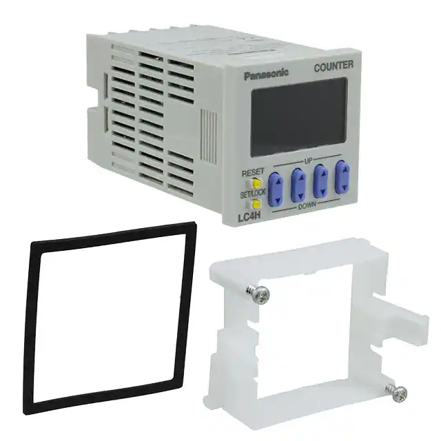
LC4H-SV
new:
DIN 48 SIZE
LCD ELECTRONIC COUNTER
Scale factor, power supply
LC4H-S
NEW FEATURES:
48
1.890
with a 12 V DC power supply 100 mA.
It is possible to connect photo-sensors,
proximity switches or encoders without additional devices.
2. 12 V DC Power Supply:
The 100 – 240 V AC types are equipped
3. Voltage Signal Input:
PNP input types are available.
64.5
2.539
48
1.890
mm inch
R4 / T4 systems (4-digit display)
R6 / T6 systems (6-digit display)
Pin type
1. Scale Factor:
A scale factor can be entered into LC4H-SV
series. After that one count shows the real
unit/value of the machine/application.
FEATURES
1. Bright and Easy-to-Read Display
A brand new bright 2-color backlight LCD
display. The easy-to-read screen in any
location makes checking and setting procedures a cinch.
4. Screw terminal and Pin Type are
Both Standard Options
The two terminal types are standard
options to support either front panel
installation or embedded installation.
2. Simple Operation
Seesaw buttons make operating the unit
even easier than before.
5. 4-digit or 6-digit display
Two sizes of displays are offered for you
to choose the one that suits your needs.
3. Conforms to IP66’s Weather
Resistant Standards
The water-proof panel keeps out water
and dirt for reliable operation even in
poor environments.
6. Conforms With EMC and Low
Voltage Directives
Conforms with EMC directives
(EN50081-2/EN50082-2) and low-voltage directives (VDE0435/Part 2021) for
CE certification vital for use in Europe.
Screw terminal type
PRODUCT TYPES
Digit
Count speed
Output
Operation voltage
Power down
insurane
100-240 V AC
with 12V DC power supply
Relay
4
12-24 V DC / 24 V AC
Transistor
30 Hz (cps)
5 kHz (kcps)
Available
switchable
100-240 V AC
with 12V DC power supply
Relay
6
12-24 V DC / 24 V AC
Transistor
Additional function
Terminal
P/N
Scale Factor
11 Pin
LC4H-PS-R4-AC240V
Scale Factor
Screw
LC4H-PS-R4-AC240VS
Scale Factor / Voltage Signal Input
11 Pin
LC4H-PSV-R4-AC240V
Scale Factor / Voltage Signal Input
Screw
LC4H-PSV-R4-AC240VS
Scale Factor
11 Pin
LC4H-S-R4-24V
Scale Factor
Screw
LC4H-S-R4-24VS
Scale Factor / Voltage Signal Input
11 Pin
LC4H-SV-R4-24V
Scale Factor / Voltage Signal Input
Screw
LC4H-SV-R4-24VS
Scale Factor
11 Pin
LC4H-S-T4-24V
Scale Factor
Screw
LC4H-S-T4-24VS
Scale Factor / Voltage Signal Input
11 Pin
LC4H-SV-T4-24V
Scale Factor / Voltage Signal Input
Screw
LC4H-SV-T4-24VS
Scale Factor
11 Pin
LC4H-PS-R6-AC240V
Scale Factor
Screw
LC4H-PS-R6-AC240VS
Scale Factor / Voltage Signal Input
11 Pin
LC4H-PSV-R6-AC240V
Scale Factor / Voltage Signal Input
Screw
LC4H-PSV-R6-AC240VS
Scale Factor
11 Pin
LC4H-S-R6-24V
Scale Factor
Screw
LC4H-S-R6-24VS
Scale Factor / Voltage Signal Input
11 Pin
LC4H-SV-R6-24V
Scale Factor / Voltage Signal Input
Screw
LC4H-SV-R6-24VS
Scale Factor
11 Pin
LC4H-S-T6-24V
Scale Factor
Screw
LC4H-S-T6-24VS
Scale Factor / Voltage Signal Input
11 Pin
LC4H-SV-T6-24V
Scale Factor / Voltage Signal Input
Screw
LC4H-SV-T6-24VS
* A rubber gasket (ATC18002) and a mounting frame (AT8-DA4) are included.
82
02/2003
�LC4H-S
Part names
• 4-digit display type
DIP switches
COUNTER
LC4H
Counter display
2
3
4
5
6
7
8
ON
1
Controlled output indicator
Set value display
Reset indicator
OP.
RST
LOCK
Lock indicator
UP
RESET
Reset switch
Up keys
SET/ LOCK
Down keys
Set/lock switch
DOWN
(Same for screw terminal type)
• 6-digit display type
DIP switches
COUNTER
LC4H
Counter display
2
3
4
5
6
7
8
ON
1
Controlled output indicator
Set value display
Reset indicator
OP.
RST
LOCK
Lock indicator
RESET
Reset switch
Up keys
SET/ LOCK
Set/lock switch
(Same for screw terminal type)
Specifications
Item
Rated operating voltage
Rated frequency
Rated power consumption
Rated control capacity
Input mode
Max. counting speed
Counting input (input 1, input 2)
Reset input
Lock input
Rating
Input signal
Output mode
One shot output time
Indication
Digit
Contact
Life
Decimal point
Pre-scaling
Memory
Power for senser
Contact arrangement
Initial contact resistance
Contact material
Mechanical (contact)
Electrical (contact)
Operating voltage range
Initial withstand voltage
Electrical
Mechanical
Operating
conditions
Initial insulation resistance
(At 500 V DC)
Temperature rise
Functional
Vibration
resistance
Destructive
Functional
Shock
resistance
Destructive
Ambient temperature
Ambient humidity
Air pressure
Connection
Protective construction
Ralay output type
AC type
100 to 240 V
DC/AC type
12 to 24 V DC/24 V AC
50/60 Hz common
Transistor output type
DC/AC type
12 to 24 V DC/24 V AC
Max. 3 W
Max. 10 V A
100 mA, 30 V DC
5 A 250 V AC (resistive load)
Addition (UP)/Subtraction (DOWN)/Direction (DIR)/Individuality (IND)/Phase (PHASE)
5 modes selectable by DIP switches
30 Hz, 5 kHz (selectable by DIP switches)
16.7 ms at 30 Hz/0.1 ms at 5 kHz ON time: OFF time = 1:1
Min. input signal width: 1 ms, 20 ms (selected by DIP switches)
Min. input signal width: 20 ms
Contact, Open collector input/DC two-wire system sensor Input impedance: 1 kΩ or less, Input residual voltage: 2 V or less,
Open impedance: 100 kΩ or less, Max. energized voltage: 40 V DC
HOLD-A, HOLD-B, HOLD-C, SHOT-A, SHOT-B, SHOT-C, SHOT-D, 7 modes selectable by DIP switches
1 s, 0.5s, 0.2s, 0.1s, 0.05, 0.01s
7-segment LCD, Counter value (backlight red LED), Setting value (backlight yellow LED)
4-digit display type –999 to 9999 (0 to 9999 for setting)
6-digit display type –99999 to 999999 (0 to 999999 for setting)
Can be set to three digits
0.001 to 9.999 (4-digit type), 0.001 to 99.999 (6-digit type)
EEP-ROM (Overwriting times: 105 ope. or more)
12 V DC (±10%) 100 mA Max.
—
1 Form A (Open collector)
1 Form C
100 mΩ (at 1 A 6 V DC)
—
Ag alloy/Au flush
—
2.0 × 10⁷ ope. (Except for switch operation parts)
—
1.0 × 10⁵ ope. (At rated control voltage)
1.0 × 10⁷ ope. (At rated control voltage)
85 to 264 V AC
10.8 to 26.4 V DC, 20.4 to 26.4 V AC
Between live and dead metal parts: 2,000 Vrms for 1 min (pin type)
Between input and output: 2,000 Vrms for 1 min
Between live and dead metal parts: Min. 100 MΩ (pin type)
Between input and output: Min. 100 MΩ
Max. 65° C (under the flow of nominal operating current at nominal voltage)
10 to 55 Hz (1 cycle/min), single amplitude: 0.35 mm .014 inch (10 min on 3 axes)
10 to 55 Hz (1 cycle/min), single amplitude: 0.75 mm .030 inch (1 h on 3 axes)
Min. 98 m/s2 (4 times on 3 axes)
Min. 294 m/s2 (5 times on 3 axes)
–10° C to 55° C +14° F to +131° F
Max. 85 % RH
860 to 1,060 h Pa
11-pin/screw terminal
IP66 (front panel with a rubber gasket)
83
02/2003
�LC4H-S
Dimensions
(units: mm inch)
Screw-down terminal type
Pin type
5.5
.217
(48
(1.890
COUNTER
55.6
2.189
70.1
2.760
14.5
.571
64.5
2.539
LC4H
((44.5)
((1.752)
OP.
(48
(1.890
5.5
.217
((44.5)
((1.752)
s
UP
RESET
SET/LOCK
DOWN
7.5
.295
73*
2.874*
87.5*
2.445*
81.9*
3.224*
* With power supply for sensor
* With power supply for sensor
(* 6-digit display type has the same dimensions.)
• Dimensions for embedded installation (with adapter installed)
Screw terminal type
Pin type
COUNTER
UP
Installation panel
Installation frame for
embedded installations
ATA4811 (supplied)
11 pin type
11 pins cap:
ATA4861 (sold separately)
LC4H
50
1.969
48
1.890
(44.5
(1.752
66
2.598
OP.
RST
LOCK
RESET
Rubber gasket
ATC18002 (supplied)
LC4H
50
1.969
48
1.890
COUNTER
Installation frame for
embedded installations
ATA4811 (supplied)
Installation panel
OP.
RST
LOCK
66
2.598
Rubber gasket
ATC18002 (supplied)
RESET
SET/LOCK
SET/LOCK
DOWN
1
.039
48
1.890
63.5
2.500
• Dimensions for front panel installations
90
3.543
1
48
1.890
80.9
3.185 * With power supply for sensor
• Installation panel cut-out dimensions
104.5
4.114
* With power supply for sensor
• For connected installations
DIN rail terminal block
11-pin type: AT8-DF11K
(sold separately)
Min. 80
3.150
45-0.6
0
1.772-.024
0
45-0.6
0
1.772-.024
0
45-0.6
0
1.772-.024
0
The standard panel cut-out dimensions are shown
below. Use the installation frame (ATA4811) and
rubber gasket (ATC18002).
A
When n units are attached in a continuous series,
the dimension of (A) is:
–0.6
A = (48 × n – 2.5) 0
Min. 80
3.150
Device installation rail
ATA48011
(sold separately)
Note 1: The installation panel thickness should be between 1
and 5 mm .039 and .197 inch.
Note 2: For connected installations, the waterproofing ability
between the unit and installation panel is lost.
95.5 (112.9)
3.760 (4.445)
* With power supply for sensor
Terminal layouts and Wiring diagrams
• Pin type
Relay output type
Reset
Input 1
Input 2
Lock
–
~
Reset
Input 1
Input 2
Lock
NC
5 6 7
4
3
2
1 11
NO
8
9
10
Operating
voltage
* With power supply for sensor
Relay output type
Transistor output type
Transistor output type
+
–
~
~
Reset
Input 1
Input 2
Lock
5 6 7
4
3
2
1 11
8
9
10
Operating
voltage
0V
DC 12V
100mA Max.
+
~
Reset
Input 1
Input 2
Lock
NO
6
7
8
9
7
8
9
10
+
~
Operating
voltage
3
–
~
4
1 11
8
9
10
~Operating~
7
8
9
Reset
Input 1
Input 2
Lock
10
6
7
8
9
10
2
3
4
5
NC
0V
2
5 6 7
4
3
2
voltage
NO
6
NC
1
0V
DC 12V
100mA Max.
~Operating~
Reset
Input 1
Input 2
Lock
6
10
1 11
NO
8
9
10
* With power supply for sensor
Relay output type
Transistor output type
Transistor output type
Reset
Input 1
Input 2
Lock
4
3
2
voltage
• Screw terminal type
Relay output type
Reset
Input 1
Input 2
Lock
NC
5 6 7
1
5
+
~
Operating
voltage
2
3
4
5
DC 12V
100mA Max.
–
11
1
0V
2
~Operating~
~
voltage
Note) For connecting the output leads of the transistor output type, refer to 5) Transistor output on page 99.
84
02/2003
3
4
5
DC 12V
100mA Max.
11
1
~Operating ~
voltage
�LC4H-S
Setting the operation mode and counter
Setting procedure 1) Setting the operation mode (input mode and output mode)
Set the input and output modes with the DIP switches on the side of the counter.
DIP switches
1
2
3
4
5
6
7
8
Table 1: Setting the output mode
Item
DIP switch
OFF
ON
Output mode
Refer to table 1
Minimum reset input signal width
Maximum counter setting
Input mode
20 ms
30 Hz
DIP switch No.
1
2
3
ON
ON
ON
OFF
OFF
OFF
ON
OFF
OFF
OFF
ON
OFF
ON
ON
OFF
OFF
OFF
ON
ON
OFF
ON
OFF
ON
ON
1 ms
5 kHz
Refer to table 2
Output mode
SHOT-A
SHOT-B
SHOT-C
SHOT-D
HOLD-A
HOLD-B
HOLD-C
— (See note 1)
Table 2: Setting the input mode
DIP switch No.
Input mode
6
7
8
ON
ON
ON
Addition input
OFF
OFF
OFF
Subtraction input
ON
OFF
OFF
Directive input
OFF
ON
OFF
Independent input
ON
ON
OFF
Phase input
OFF
OFF
ON
— (See note 1)
ON
OFF
ON
— (See note 1)
OFF
ON
ON
— (See note 1)
Notes:1) The counter and set value displays will display DIP Err.
Notes:2) Set the DIP switches before installing the counter on the panel.
Notes:3) When the DIP SW setting is changed, turn off the power once.
Notes:4) The DIP switches are set as ON before shipping.
DIP switches (See note 2)
2
3
4
5
6
7
8
ON
1
(Same for 6-digit, screw-down terminal type)
Setting procedure 2) Setting the set value
Set the set value with the UP and DOWN keys on the front of the counter.
Front display section
• 4-digit display type
Q Counter display
W Set value display
E Controlled output indicator
R Reset indicator
T Lock indicator
Y UP keys
Changes the corresponding
digit of the set value in the
addition direction (upwards)
• 6-digit display type
Q Counter display
W Set value display
E Controlled output indicator
R Reset indicator
T Lock indicator
COUNTER
LC4H
1
3
4
2
OP.
RST
LOCK
5
6
UP
RESET
8
7
SET/LOCK
9
DOWN
COUNTER
LC4H
1
3
4
2
OP.
RST
LOCK
5
6
RESET
7
SET/LOCK
8
U DOWN keys
Changes the corresponding digit of the set
value in the subtraction direction (downwards)
I RESET switch
Resets the counting value and the output
O SET/LOCK switch
This is used to handle pre-scaling values,
one-shot times, decimal point position settings, and key lock operations (to disable Up
key, Down key, and Reset key operations).
Y UP keys
Changes the corresponding digit of the set
value in the addition direction (upwards)
U RESET switch
Resets the counting value and the output
I SET/LOCK switch
This is used to handle pre-scaling values,
one-shot times, decimal point position settings, and key lock operations (to disable Up
key, Down key, and Reset key operations).
Setting procedure 3) Setting the input mode
The input mode is set using the key switch in the [Display] section on the front of the counter.
• Decimal point position setting mode
Q Holding down the [SET/LOCK] key, press the key for the second digit to access the decimal point position setting mode.
Example) 6-digit type
Decimal point position setting mode display
(Example shows default value displayed)
W When the setting mode has been accessed, release the [SET/LOCK] key.
85
02/2003
�LC4H-S
E The decimal point is set using the [UP] and [DOWN] keys to specify the 2nd, 3rd, and 4th digits (this applies only to 4-digit
models).(The 1st digit is set using the [UP] key or [DOWN] key in settings where there is no decimal point (this applies
only to 4-digit models).)
Example) 6-digit type
Example shows 2nd digit displayed using [UP] key
R Press the [RESET] key to set the displayed decimal point position and return to normal operation.
• Setting the pre-scaling value
Q Holding down the [SET/LOCK] key, press the key for the first digit to access the pre-scaling value setting mode.
Example) 4-digit type
Example) 6-digit type
Pre-scaling value setting mode displayed
(Example shows default values displayed)
W When the setting mode has been accessed, release the [SET/LOCK] key.
E Use the [UP] or [DOWN] key to set the pre-scaling value (this applies only to 4-digit models).
Select either: 0.001 to 9.999 (4-digit) or 0.001 to 99.999 (6-digit)
R Press the [RESET] key to set the displayed pre-scaling value and return to normal operation.
• Setting the one-shot output time
Q Holding down the [SET/LOCK] key, press the key for the third digit to access the one-shot output time setting mode.
Example) 6-digit type
One-shot output time setting mode displayed
(Example shows default value displayed)
W When the setting mode has been accessed, release the [SET/LOCK] key.
E Each time the 1st-digit [UP] key is pressed, the one-shot output time changes in the following sequence, moving to the
right:
→ 1 s → 0.5 s → 0.2 s → 0.1 s → 0.05 s → 0.01 s
(With a 4-digit type, the [DOWN] key can also be used to move to the left.)
R Press the [RESET] key to set the displayed one-shot output time and return to normal operation.
Changing the set value
1. It is possible to change the set
value with the up and down keys (4digit type only) even during counting.
However, be aware of the following
points.
1) If the set value is changed to less than
the count value with counting set to the
addition direction, counting will continue
until it reaches full scale (9999 with the
4-digit type and 999999 with the 6-digit
type), returns to zero, and then reaches
the new set value. If the set value is
changed to a value above the count
value, counting will continue until the
count value reaches the new set value.
2) Suppose that thew counter is preset to
count down. Whether a preset countdown value is smaller or larger than the
count value, the counter counts down to
“0 (zero)”.
2. If the set value is changed to “0,”
the unit will not complete count-up. It
starts counting up when the counting
value comes to “0 (zero)” again.
1) Up-count (addition) input
When counting is set to the addition
direction, counting will continue until full
scale is reached (9999 with the 4-digit
type and 999999 with the 6-digit type),
return to zero, and then complete countup.
2) Down-count (subtraction) input
When counting is set to the subtraction
direction, counting will continue until full
scale is reached (-999 with the 4-digit
type and -99999 with the 6-digit type),
and then the display will change to
with the 4-digit type and
with the 6-digit type.
The counting value does not become “0
(zero)” and so the counter does not
count up.
3) Directive, independent, and phase
inputs
The counting value is counted up or
down to any number other than “0” once.
When it comes to “0 (zero)” again, the
counter starts counting up.
CAUTIONS FOR USE
For more information regarding the cautions for use of LC4H series counter, refer to page 118 “LC4H series CAUTIONS FOR USE”.
86
02/2003
�LC4H-S
Operation mode
1. Input mode
For the input mode, you can choose one of the following five modes
• Addition
• Subtraction
UP
DOWN
• Directive
DIR
• Independent
IND
• Phase
Input mode
PHASE
Operation
IN1 or IN2 works as an input block
(gate) for the other input.
*Minimum input signal width 30 Hz: 16.7 ms; 5 kHz: 0.1 ms
• Example where IN1 is the counting input and IN2 is the input block (gate).
IN1
H
L
A A
A A
Blocked
Addition
IN2
UP
H
L
Counting (addition)
0
1
2
3
n-3
n-2
n-1
n
Counting (subtraction)
n
n-1
n-2
n-3
3
2
1
0
Reset
Count-up completed
• Example where IN2 is the counting input and IN1 is the input block (gate).
IN1
IN2
Subtraction
DOWN
H
L
Blocked
Blocked
A A
A A
H
L
Counting (addition)
Counting (subtraction)
0
1
2
3
4
n-1
n
n-1
n-2
n-3
n-4
1
n
0
Count-up completed
Reset
* “A” must be more than the minimum input signal width.
IN1 is the counting input and IN2 is the
addition or subtraction directive input.
IN2 adds at L level and subtracts at H
level.
Directive
IN1
A A
Addition
IN2
DIR
H
L
A A
Subtraction
Addition
H
L
0
Counting
1
2
3
4
3
2
1
0
1
2
3
4
Reset
* “A” must be more than the minimum input signal width.
IN1 is addition input and IN2 is subtraction input.
IN1
H
L
Independent
IN2
H
L
IND
Counting
0
1
2
3
4
3
2
1
2 1
2
3
Reset
* IN1 and IN2 are completely independent, so there is no restriction on signal
timing.
Addition when the IN1 phase advances
beyond IN2, and subtraction when the
IN2 phase advances beyond IN1.
Phase
IN1
H
L
IN2
H
L
B B
Phase advance
PHASE
Counting
0
1
Phase retard
2
3
2
1
0
Reset
* “B” must be more than the minimum input signal width.
87
02/2003
�LC4H-S
2. Output mode
For the output mode, you can choose one of the following seven modes
• Maintain output/hold count
HOLD-A
• Maintain output/over count I
HOLD-B
• Maintain output/over count II
HOLD-C
• One shot/over count
SHOT-A
• One shot/recount I
SHOT-B
• One shot/recount II
SHOT-C
• One shot/hold count
SHOT-D
Output mode
Maintain output
Hold count
HOLD-A
Operation
Output control is maintained after
count-up completion and until resetting.
During that time, the count display does
not change from that at count-up completion.
(Example when input mode is either addition or subtraction)
n-3
n-2
n-1
Counting (subtraction)
3
2
1
Counting able/unable
Able
Counting (addition)
n
0
Unable
ON
Output control
OFF
* n: Set value
Maintain output
Over count I
Output control is maintained after
count-up completion and until resetting.
However, counting is possible despite
completion of count-up.
Counting (addition)
Counting (subtraction)
n-2
n-1
n
n+1
n+2
2
1
0
-1
-2
Able
Counting able/unable
HOLD-B
Output control
ON
OFF
* n: Set value
Maintain output
Over count II
HOLD-C
Output control is maintained after
count-up completion and until the next
signal enters. However, counting is
possible despite completion of countup.
Counting (addition)
Counting (subtraction)
n-2
n-1
n
n+1
n+2
2
1
0
-1
-2
Able
Counting able/unable
ON
Output control
OFF
OFF
* n: Set value
One shot
Over count
Output control is maintained after
count-up completion for one shot output
time. Counting is possible despite completion of count-up.
Counting (addition)
Counting (subtraction)
n-2
n-1
2
1
Counting able/unable
One shot
Recount I
SHOT-B
One shot
Recount II
SHOT-C
Output control is maintained after
count-up completion for one shot output
time. Counting is possible despite completion of count-up. However, reset
occurs simultaneous with output OFF.
n+2
0
-1
-2
ON
OFF
OFF
Approx. 1s
* n: Set value
Output control is maintained after
count-up completion for one shot output
time. Counting is possible despite completion of count-up. However, reset
occurs simultaneous with completion of
count-up. While output is being maintained, restarting of the count is not
possible
n+1
Able
SHOT-A
Output control
n
Counting (addition)
Counting (subtraction)
n-2
n-1
2
1
0
1
2
n
n-1
n-2
Reset (automatic)
Able
Counting able/unable
ON
Output control
OFF
OFF
Approx. 1s
* n: Set value
Counting (addition)
Counting (subtraction)
n-1
n
n+1
1
0
-1
0
1
n
n-1
Reset (automatic)
Able
Counting able/unable
ON
Output control
OFF
OFF
Approx. 1s
* n: Set value
One shot
Hold count
SHOT-D
Output control is maintained after
count-up completion for one shot output
time. During that time, the count display
does not change from that at count-up
completion. Reset occurs simultaneous
with output OFF.
Counting (addition)
Counting (subtraction)
n-1
n
1
0
0
1
n
n-1
Reset (automatic)
Able
Counting able/unable
Unable
Able
ON
Output control
* n: Set value
88
02/2003
OFF
OFF
Approx. 1s
�LC4H-S
Input connections
• Signal input type
•) Open collector
•) For voltage output
+
(Photoelectric sensor,
proximity sensor, etc.)
12 V DC
Output
0V
0V
–
7
0V
6
8
9
7
1
11-pin type
Screw-down
terminal type
10 11
Lock Input Input Reset 12 V DC
1 input output
input 2
•) Contact input
3
6
0V
•) For a rotary encoder
4
5
6
7
7
8
9
10 11
Lock Input Input Reset 12 V DC
1 input output
input 2
•) PNP transistor type
12 V DC
Relay, switches etc.
sensor and others
DC12V
A
phase
11-pin type
3
4
5
6
7
Screw-down
terminal type
6
7
8
9
10
Lock Input Input Reset
1 input
input 2
0V
11-pin type
3
5
6
1
Screw-down
terminal type
6
8
9
11
0V
OUTPUT
B
phase
11 Pin type
3 5 6 7 1
Screw terminal type
6
8
Input 2
0V
1
Input Input 12 V DC
2
1 output
Input 1, input 2, and reset input specifications
Lock input specifications
• Impedance during short-circuit: 1 kΩ max.
(At 0 Ω, the outflow current is approximately 12 mA.)
• Residual voltage during short-circuit: 2 V max.
• Impedance when released: 100 kΩ min.
• Max. applied voltage: 40 VDC max.
• Impedance during short-circuit: 1 kΩ max.
9
10 11
DC12V output
6
5
Input 1
4
Reset input
3
Screw-down
terminal type
12 V DC
Output
–
11-pin type
0V
+
0V
(PC, sensor etc.)
(At 0 Ω, the outflow current is approximately 1.5 mA.)
• Residual voltage during short-circuit: 2 V max.
• Impedance when released: 100 kΩ min.
• Max. applied voltage: 40 DVC max.
• The contact relay should be one which can open/close 5 V,
1.5 mA.
* There is no 12 V DC with 12 - 24 V DC/24 V AC types.
What is the prescale function?
•) For a dual-line sensor
The prescale function converts the count into an actual
value (amount) and displays it.
Example
For a device that outputs 500 pulses when 1 m has been fed:
1. Set decimal position to the last 3rd place.
2. Set the prescale value to 0.002 (1/500).
+
0V
—
11-pin type
3
5
6
7
Screw-down
terminal type
6
8
9
10
0V
1m
3.281ft
Input Input Reset
2
1 input
Dual-line sensor specifications
COUNTER
• Leakage current: 1.5 mA max.
1 pulse
• Breaker capacitance: 5 mA min.
RESET
LC4H
UP
Can be set to
easy-to-understand
unit.
SET/LOCK
DOWN
• Residual voltage: 2.0 V max.
• Usable voltage: Runs on 10 VDC
Prescale value: 0.002
Encoder
* If a dual-line sensor is connected to a 12 - 24 VDC/24 VAC type,
24 VDC (21.6 to 26.4 VDC) and 24 VAC (21.6 to 26.4 VAC)
should be applied to the power supply voltage of the counter.
COUNTER
500 pulses
RESET
LC4H
UP
SET/LOCK
DOWN
89
02/2003
�LC4H series CAUTIONS FOR USE
PRECAUTIONS DURING USAGE
1. Terminal wiring
1) When wiring the terminals, refer to the
terminal layout and wiring diagrams and
be sure to perform the wiring properly
without errors.
2) For embedded installation applications, the screw-down terminal type is
recommended.
Use either the rear terminal block (AT8RR) or the 8P cap (AD8-RC) for the 8pin type, and the 11P cap (AT8-DP11)
for the 11-pin type. Avoid soldering
directly to the round pins on the unit.
For front panel installation applications,
use the 11-pin type DIN rail terminal
block (ATC18004).
3) After turning the unit off, make sure
that any resulting induced voltage or
residual voltage is not applied to power
supply terminals W through U (8-pin
type), W through P (11-pin type) or 1
and 2 (screw-down terminal type). (If
the power supply wire is wired parallel to
the high voltage wire or power wire, an
induced voltage may be generated
between the power supply terminals.)
4) Have the power supply voltage pass
through a switch or relay so that it is
applied at one time. If the power supply
is applied gradually, the counting may
malfunction regardless of the settings,
the power supply reset may not function,
or other such unpredictable occurrence
may result.
2. Input connections
The power circuit has no transformer.
When an input signal is fed to two or
more counters at once, do not arrange
the power circuit in an independent way.
If the counter is powered on and off independently as shown in Fig. A, the counter's internal circuitry may get
damaged.Be careful never to allow such circuitry. (Figs. A, B and C show the circuitry for
the 11-pin type.)
(Fig. A)
Input contact
point or transistor
Input
terminal
3
2
10
Power
supply
Input
terminal
3
2
10
If independent power circuitry must be used,
keep the input contacts or transistors separate from each other, as shown in Fig. B.
When power circuitry is not independent,
age of less than 2 V when the transistor
is on.
* The short-circuit impedance should be
(Fig. B)
Input contact
point or transistor
Input
terminal
3
10
2
Reset input
Power
supply
Input 1
Input 2
Lock
input
Input contact
point or transistor
Input
terminal
3
10
2
one input signal can be fed to two or
more counters at once, as shown in Fig. C.
3. Input and output
8-pin type
1
—
5
4
11-pin type
3
4
5
6
7
Screw terminal type
6
7
8
9
10
3
Note: The LC4H-W does not have the lock input
R7.
less than 1 kΩ.
(Fig. C)
Input contact
point or transistor
Input
terminal
3
10
2
Power
supply
[When the impedance is 0 W, the current
coming from the input 1 and input 2 terminals is approximately 12 mA, and from
the reset input and lock input terminals is
approximately 1.5 mA.]
Also, the open-circuit impedance should
be more than 100 kΩ.
Input
terminal
3
10
2
1) Signal input type
(1) Contact point input
Use highly reliable metal plated contacts.
Since the contact point’s bounce time
leads directly to error in the count value,
use contacts with as short a bounce time
as possible. In general, select Input 1
and Input 2 to have a maximum counting
speed of 30 Hz and to be reset with a
minimum input signal width of 20 ms.
(2) Non-contact point input
* As shown in the diagram below, from a
non-contact point circuit (proximity
switches, photoelectric switches, etc.)
with a power supply voltage of between
12 and 40 V, the signal can be input
without using an open collector transistor. In the case of the diagram below,
when the non-contact point transistor Q
switches from off to on (when the signal
voltage goes from high to low), the signal is input.
2) The input mode and output mode
12 to 40V DC
Reset input
Reset input
Input 1
Q
Input 2
Lock
input
8-pin type
1
—
5
4
11-pin type
3
4
5
6
7
Screw terminal type
6
7
8
9
10
3
Note: The LC4H-W does not have the lock input
R7.
Connect with an open collector. Use
transistors whose characteristics satisfy
the criteria given below.
VCEO = 20 V min.
IC = 20 mA min.
ICBO = 6µA max.
Also, use transistors with a residual volt-
98
02/2003
8-pin type
1
—
5
4
11-pin type
3
4
5
6
7
Screw terminal type
6
7
8
9
10
3
(The above example is for reset input)
change depending on the DIP switch settings. Therefore, before making any connections, be sure to confirm the operation mode and operation conditions currently set.
3) For the power supply of the input
�device, use a single-phase or doublephase insulated power transformer. The
second-phase side must not be grounded.
4) Since the power supply circuitry does
4. Output mode setting
The output mode can be set with the
DIP switches on the side of the counter.
Make the DIP switch settings before
installing the counter on the panel.
Leakage current
Operation power supply
R
C
C
LC4H counter
Rectifier circuits
Power
supply
Circuit
Insulated transformer
is necessary
not contain a transformer, be aware that
it is not possible for simultaneous input
from an input contact point or transistor
to a LC4H counter with independent
power supply operation.
5) The input signal is applied by the
shorting of each input terminal with the
common terminal (terminal 1 for 8-pin
type, terminal 3 for 11-pin type and terminal 6 for screw-down terminal types).
Never connect other terminals or voltages higher than DC 40 V, because it
may destroy the internal circuitry.
6) Transistor output
(1) Since the transistor output is insulated
from the internal circuitry by a photocoupler, it can be used as an NPN output or PNP (equal value) output. (The
above example is 11-pin type)
(2) Use the diode connected to the out-
5. Conditions of usage
1) Avoid locations subject to flammable
or corrosive gases, excessive dust, oil,
vibrations, or excessive shocks.
2) Since the cover of the unit is made of
polycarbonate resin, avoid contact with
or use in environments containing methyl
alcohol, benzene, thinners, and other
organic solvents; and ammonia, caustic
sodas, and other alkaline substances.
3) If power supply surges exceed the values given below, the internal circuits may
become damaged. Be sure to use surge
absorbing element to prevent this from
happening.
Operating voltage Surge voltage (peak value)
AC type
6,000V
DC type
1,000V
24V AC type
• Surge wave form
[± (1.2 × 50) ms uni-polar full wave voltage]
100
90
Surge voltage (%)
Input
terminals
O
LC4H counter
As PNP output
R
R
R
0
1.2
50
Relay
C
Counter
Receive output
from contact
at relay R
Power supply terminals
Input
DC type terminals
AC type
24V AC type
Load’s power supply
Note: With the LC4H 8-pin type and the LC4H-W,
there is no diode between points I and O.
put transistor’s collector for absorbing
the reverse voltage from induced loads.
(LC4H only)
7) When wiring, use shielded wires or
LC4H counter
Inductive load
IF (forward current): 1 A
VR (reverse voltage): 600 V
R
C
I
Load
Diode rating:
6) Long periods of continuous operation
in the count-up completed condition (one
month or more) will result in the weakening of the internal electrical components
from the generated heat and, therefore,
should be avoided. If you do plan to use
the unit for such continuous operation,
use in conjunction with a relay as shown
in the circuit in the diagram below.
4) Regarding external noise, the values
below are considered the noise-resistant
voltages. If voltages rise above these
values, malfunctions or damage to the
internal circuitry may result, so take the
necessary precautions.
Load’s power supply
O
(Fig. B)
Time (µs)
I
Load
{
C
C
30
0
{
R
Operation power supply
Peak value
50
LC4H counter
As NPN output
(Fig. A)
Load’s
power supply
Noise
voltage
1,500V
1,000V
600V
Noise wave form (noise simulator)
Rise time: 1 ns
Pulse width: 1 µs, 50 ns
Polarity: ±
Cycle: 100 cycles/second
5) When connecting the operation power
supply, make sure that no leakage current enters the counter. For example,
when performing contact protection, if
set up like that of diagram A, leaking current will pass through C and R, enter the
unit, and cause incorrect operation.
Diagram B shows the correct setup.
metallic wire tubes, and keep the wire
lengths as short as possible.
99
02/2003
�6. Self-diagnosis function
If a malfunction occurs, one of the following displays will appear.
Display
or
Contents
Minimum value went below –999
or –99999. See note 1.
Output condition
No change
Incorrect DIP switch setting.
Malfunctioning CPU.
Malfunctioning memory. See
note 2.
OFF
Restoration procedure
Enter reset or RESET
key.
Restart unit (correct DIP
switch settings)
Enter reset, RESET key,
or restart unit.
Preset values after restoration
No change
The values at start-up before the CPU
malfunction occurred.
0
Note 1: When the counter value goes below the minimum value during any of the subtraction, directive, independent, or phase input modes.
Note 2: Includes the possibility that the EEPROM’s life has expired.
7. CE Marking Certification
1) EMC directive (89/336/EEC)
As a counter unit, the LC4H series conforms to EMC directives. Applicable
standards are EN50081-2 and EN500822.
2) Low voltage directive (73/23/EEC)
In order to satisfy VDE0435/Part 2021,
be sure to adhere to the following installation conditions and precautions.
(1) The counter uses a non-transformer
power supply and the power supply and
input signal terminals are not insulated.
• When a sensor is connected to the
input circuit, install double insulation on
the sensor side.
• With contact-point inputting, use double-insulated relays, etc.
(2) Always connect loads insulated with
basic insulation specifications to the output contact points. The counter unit is
also insulated with basic insulation specifications. The combination of the two satisfies VDE, which calls for double insulation.
(3) For the applied power supply, use
one protected by an over-current protec-
100
02/2003
tion device that conforms with EN/IEC
standards (e.g. 250 V, 1 A fuse).
(4) During installation, always use a terminal block or the appropriate sockets.
Do not touch the terminals, or other part
of the counter unit while it is on. Before
installation or removal of the unit, first
verify that no voltage is being applied to
any of the terminals.
(5) Do not use the counter in a safety circuit. When the unit is being used in a circuit such as a heater circuit, install a protection circuit on the machine side.
�