Panasonic
New Product Introduction
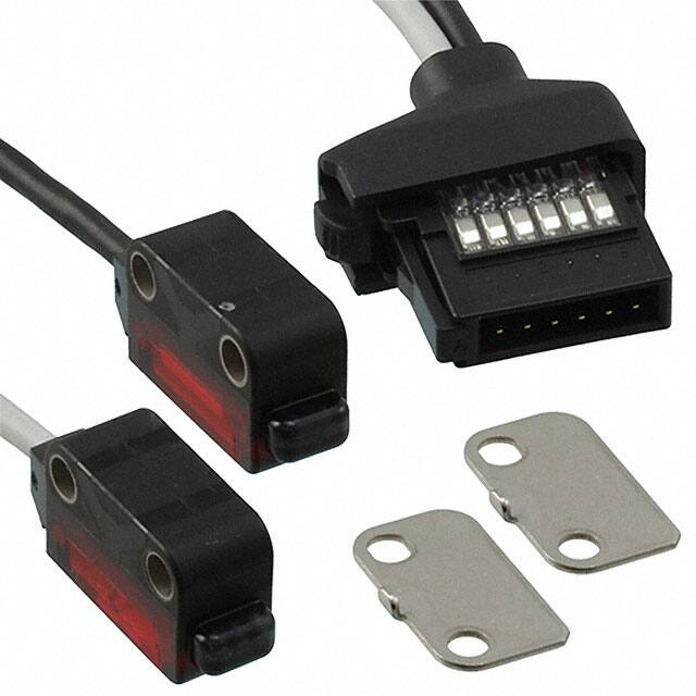
New LS-500 Series
Digital Laser Sensor
RoHS
COMPLIANT
Laser Sensor with Compact Sensors Heads and an Available 4-20 mA Output!
Panasonic, a worldwide leader in Factory Automation Products, is pleased to introduce the NEW LS-500 Series
digital laser sensors. The LS-500 Series is a Class 1 laser sensor that saves production time and money with
speed and ease-of-use. It has a threshold tracking feature that allows the sensor to adjust its threshold to
compensate for tough environments such as those with dust and dirt. In addition to its effectiveness in dirty
settings, the LS-500 Series boasts one of the industry’s fastest response times at 60 microseconds of detection
time. This high precision laser sensor is engineered to be integrated with other Panasonic products such as the
FX-500 Series fiber sensors, which minimizes wiring and diminishes cost. The LS-500 Series is in the top of its
class among laser sensors in the high function, high application market. This small unit has dual outputs that can
be independently configured for different threshold values. The device eliminates the need for a dedicated logic
controller by performing AND, OR, and XOR logic operations. The LS-500 Series has a built-in memory that can
store up to eight sets of amplifier settings. This memory function reduces downtime when changing the setup in a
multi-model production environment. The LS-500 Series laser sensor improves operations and production time
in any market.
Features
• 4 Small-Sized Sensor Head Configurations
• Analog Output, 4 to 20 mA (LS-501-C2 only)
• Connection to CC-Link, and RS-485* (Using SC-GU3)
• 8 Data Banks with Logic Functions
• RoHS Compliant
Part Number Information
Sensor Amplifiers
5
LS
0
LS-500 Series Amplifier
1
P
C2
Output
Connection
Method
*EtherCAT and DeviceNet Support Coming Soon!
Benefits
• Precision Detection in a Small Footprint
• Can Be Used to Track Movement and Distance Gauging
• Can Be Integrated into Communication Networks
• Offers Multiple Application Recipes
• AND, OR, and XOR Logic Functionality Built-In
Industries
• Semiconductor
• Packaging
• Medical
Applications
• Wafer Detection and Mapping
• Label and Bottle Detection
• Pill and Tube Detection
Website: www.panasonic.com/industrial
industrial@us.panasonic.com
1-800-344-2112
2 NPN
2 PNP
Nil
P
Nil
C2
Quick Connect
2M Cable
Sensor Heads
LS
H
LS-500 Series Heads
101
102
201
901
101
C5
Type
Connection
Method
Thrubeam - Cylindrical
Thrubeam - Square
Coaxial Reflective
Coaxial Retroreflective
Nil
C2
2M Cable
5M Cable
Copyright © 2013 Panasonic Corporation of North America.
All Rights Reserved. Specifications are subject to change without notice.
LS-500 Series NPI, FY13-082-XXX
�
很抱歉,暂时无法提供与“LS-H102”相匹配的价格&库存,您可以联系我们找货
免费人工找货- 国内价格 香港价格
- 1+2915.569351+376.11591