Amplifier-separated
Rectangular-shaped Inductive Proximity Sensor
GX-F/H SERIES
2022.5
* The contents of this catalog are as of October 2017.
For the latest information, please visit our company website.
�Rectangular-shaped Inductive Proximity Sensor
GX-F/H SERIES
Amplifier Built-in
PNP output
Oil resistant
type available
Industry No. 1* in stable sensing
Different freq.
type available
* �Based on research conducted by Panasonic Industrial Devices SUNX
as of November 2012 among equivalent rectangular inductive sensors.
Can be installed with ample space
This sensor has the longest stable sensing range among the same level of rectangular inductive proximity sensors in
the industry. It is easy to install the sensor.
Maximum operation distance
Type
Stable sensing range
GX-F/H
series
Conventional
model
Stable sensing range
Maximum
operation
distance
GX-F/H
series
Conventional
model
GX-□6
1.6 mm 0.063 in
0 to 1.3 mm 0.051 in
0 to 1.2 mm 0.047 in
GX-□8
2.5 mm 0.098 in
0 to 2.1 mm 0.083 in
0 to 1.8 mm 0.709 in
GX-□12
4.0 mm 0.157 in
0 to 3.3 mm 0.130 in
0 to 3.0 mm 0.118 in
GX-□15
5.0 mm 0.197 in
0 to 4.2 mm 0.165 in
0 to 4.0 mm 0.157 in
8.0 mm 0.315 in
0 to 6.7 mm 0.264 in
0 to 6.4 mm 0.252 in
Long sensing
range
* With standard sensing object
Variation at the maximum operation distance is within ±8 %
Temperature characteristics vary within ±8 %
Thorough adjustment and control of sensing sensitivity
greatly reduces individual sensor differences and
variations.
The work of adjusting sensor positions when using
multiple sensors and when sensors have been replaced
is much easier.
Components such as the sensor coil and core and
product design have been totally revised to provide
excellent temperature characteristics.
Stable sensing can be obtained regardless of the time of
day or the yearly season.
Example: GX-□8
0.4 mm 0.016 in or less
Standard
sensing object
60%
less
1.0 mm 0.039 in or less
Operation distance variation: 0.4 mm 0.016 in or less*
For the
GX-□8
Maximum operation distance: 2.5 mm 0.098 in ± 8 %
(2.3 to 2.7 mm 0.091 to 0.106 in)
Operation distance variation: 1.0 mm 0.039 in or less
Standard
sensing
object
Maximum operation distance: 2.5 mm 0.098 in ± 20 %
(2.0 to 3.0 mm 0.079 to 0.118 in)
* Not including temperature characteristics.
Image
Conventional
model
Rate of variation in sensing range [%]
2
16.0
14.0
12.0
10.0
8.0
6.0
4.0
2.0
0.0
–2.0
GX-F/H series
Conventional models
Sensing range within temperatures
of –25 to +70 °C
(–13 to +158 °F) are within
±8 % of the range at +23 °C (+73 °F)
Conventional models:
within +15
–10 %
(
23 °C
73 °F
–20 –10
–4 14
0
32
10
50
20
68
30
86
40 50 60 70
104 122 140 158
Ambient temperature [°C °F]
* Typical
)
�Rectangular-shaped Inductive Proximity Sensor
GX-F/H SERIES
APPLICATIONS
Muting control of light curtains
Positioning processing equipment
Positioning metal pallets
ENVIRONMENTAL RESISTANCE
10 times the durability! (Compared to conventional models)
The new integrated construction method used provides shock resistance of 10,000 m/s2 (approx. 1,000 G in X, Y and Z directions for
three times each), and vibration resistance clears durability tests of between 10 and 500 Hz (3 mm 0.118 in double amplitude in X, Y
and Z directions for 2 hours each). In addition, resistance to impulse noise is approx. three times greater than for conventional models.
Checking up / down
operation of
compact molding
equipment
Sensing presence of metallic
objects on a part feeder
Shock resistance:
1,000 G
Vibration resistance: 500 Hz
FUNCTIONS
Highly resistant to water or oil!
IP68G* protective construction
Indicators are easy to see over a wide field of view
The new integrated construction method used improves
environmental resistance performance.
The IP68G prevents damage to the sensor by stopping
water and oil getting inside.
A prism with a wide field of view has been developed. This
has greatly improved the visibility of the operation indicators.
GX-H□
* For details, refer to the “SPECIFICATIONS (p.7~)”.
GX-F□
MOUNTING
Tightening strength increased with no damage! (excluding GX-□6)
Conductor thickness doubled to make wiring much easier! (GX-□6 / GX-□8 only)
A metal sleeve has been inserted.
It prevents the sensor from being damaged by tightening
too much.
The conductor’s thickness was doubled for the GX-□6 / GX-□8.
This makes it easier to handle and perform crimping work on
the cables. In addition, the tensile strength of the crimping area
has become higher.
GX-□8, GX-□12
GX-□15
Metal sleeve
0.08 mm2
Conventional model
0.15 mm2
GX-□6, GX-□8
Metal sleeve
Approx. 1.4 times
greater than before
M3 screw
Tightening torque: 0.7 N・m or less
M3 screw
Tightening torque: 1 N・m or less
Conductor thickness approx.
2 times greater
3
�4
Rectangular-shaped Inductive Proximity Sensor
GX-F/H SERIES
ORDER GUIDE
GX-6 type
Appearance (mm in)
Sensing range (Note 1)
Model No.
(Note 2)
Output
GX-F6A
Front sensing
Top sensing
Front sensing
Top sensing
PNP output
NPN output
Type
6 0.236
6 0.236
GX-F6B
GX-F6BI
GX-H6A
6 0.236
6 0.236
25
0.984
Maximum
operation distance
1.6 mm 0.063 in
(0 to 1.3 mm 0 to 0.051 in)
6 0.236
6 0.236
6 0.236
Normally closed
NPN open-collector
transistor
Normally open
GX-H6AI
GX-H6B
Normally closed
GX-H6BI
GX-F6A-P
Normally open
GX-F6AI-P
24.5
0.965
Stable sensing range
GX-F6B-P
GX-F6BI-P
GX-H6A-P
6 0.236
Normally open
GX-F6AI
24.5
0.965
Normally closed
PNP open-collector
transistor
Normally open
GX-H6AI-P
GX-H6B-P
25
0.984
Output operation
Normally closed
GX-H6BI-P
Notes: 1) The maximum operation distance stands for the maximum distance for which the sensor can detect the standard sensing object.
The stable sensing range stands for the sensing range for which the sensor can stably detect the standard sensing object even if there is an ambient
temperature drift and/or supply voltage fluctuation.
2) “ I ” in the model No. indicates a different frequency type.
GX-8 type
Front sensing
Top sensing
Front sensing
Top sensing
PNP output
NPN output
Type
Appearance (mm in)
Sensing range (Note 1)
Model No.
(Note 2)
Output
GX-F8A
8 0.315
GX-F8B
23
0.906
GX-F8BI
GX-H8A
8.2 0.323
8 0.315
25
0.984
Maximum
operation distance
2.5 mm 0.098 in
(0 to 2.1 mm 0 to 0.083 in)
8 0.315
Normally open
GX-H8AI
GX-H8B
Normally closed
GX-H8BI
GX-F8A-P
23
0.906
Stable sensing range
Normally open
GX-F8B-P
GX-F8BI-P
GX-H8A-P
8.2 0.323
Normally closed
NPN open-collector
transistor
GX-F8AI-P
7.4 0.291
8 0.315
Normally open
GX-F8AI
7.4 0.291
GX-H8AI-P
25
0.984
GX-H8B-P
GX-H8BI-P
Output operation
Normally closed
PNP open-collector
transistor
Normally open
Normally closed
Notes: 1) The maximum operation distance stands for the maximum distance for which the sensor can detect the standard sensing object.
The stable sensing range stands for the sensing range for which the sensor can stably detect the standard sensing object even if there is an ambient
temperature drift and/or supply voltage fluctuation.
2) “ I ” in the model No. indicates a different frequency type.
�Rectangular-shaped Inductive Proximity Sensor
GX-F/H SERIES
ORDER GUIDE
GX-12 type
Front sensing
Top sensing
Front sensing
PNP output
Top sensing
NPN output
Type
Appearance (mm in)
Sensing range (Note 1)
Model No.
(Note 2)
Output
GX-F12A
12
0.472
GX-F12B
27.8
1.094
GX-F12BI
GX-H12A
12 0.472
12 0.472
27.4
1.079
Maximum
operation distance
4.0 mm 0.157 in
(0 to 3.3 mm 0 to 0.130 in)
Normally open
GX-H12AI
GX-H12B
Normally closed
GX-H12BI
GX-F12A-P
27.8
1.094
Stable sensing range
Normally open
GX-F12B-P
GX-F12BI-P
GX-H12A-P
Normally closed
PNP open-collector
transistor
Normally open
GX-H12AI-P
12 0.472
12 0.472
Normally closed
NPN open-collector
transistor
GX-F12AI-P
7.1 0.280
12
0.472
Normally open
GX-F12AI
7.1 0.280
GX-H12B-P
27.4
1.079
Output operation
Normally closed
GX-H12BI-P
Notes: 1) The maximum operation distance stands for the maximum distance for which the sensor can detect the standard sensing object.
The stable sensing range stands for the sensing range for which the sensor can stably detect the standard sensing object even if there is an ambient
temperature drift and/or supply voltage fluctuation.
2) “ I ” in the model No. indicates a different frequency type.
GX-15 type
Front sensing
Top sensing
Front sensing
PNP output
Top sensing
NPN output
Type
Appearance (mm in)
Sensing range (Note 1)
Model No.
(Note 2)
Output
GX-F15A
15 0.591
GX-F15B
31.5
1.240
GX-F15BI
GX-H15A
16.5 0.650
15 0.591
29.5
1.161
Maximum
operation distance
5.0 mm 0.197 in
(0 to 4.2 mm 0 to 0.165 in)
31.5
1.240
Normally open
GX-H15AI
GX-H15B
Normally closed
GX-H15BI
GX-F15A-P
Stable sensing range
Normally open
GX-F15B-P
GX-F15BI-P
GX-H15A-P
GX-H15AI-P
16.5 0.650
15 0.591
Normally closed
NPN open-collector
transistor
GX-F15AI-P
8 0.315
15 0.591
Normally open
GX-F15AI
8 0.315
29.5
1.161
GX-H15B-P
GX-H15BI-P
Output operation
Normally closed
PNP open-collector
transistor
Normally open
Normally closed
Notes: 1) The maximum operation distance stands for the maximum distance for which the sensor can detect the standard sensing object.
The stable sensing range stands for the sensing range for which the sensor can stably detect the standard sensing object even if there is an ambient
temperature drift and/or supply voltage fluctuation.
2) “ I ” in the model No. indicates a different frequency type.
5
�6
Rectangular-shaped Inductive Proximity Sensor
GX-F/H SERIES
ORDER GUIDE
GX-15 (Long sensing range) type
Front sensing
Top sensing
Front sensing
Top sensing
PNP output
NPN output
Type
Appearance (mm in)
Sensing range (Note 1)
Model No.
(Note 2)
Output
GX-FL15A
Normally open
GX-FL15AI
8 0.315
GX-FL15B
31.5
1.240
15 0.591
GX-FL15BI
GX-HL15A
16.5 0.650
15 0.591
29.5
1.161
Normally closed
NPN open-collector
transistor
Normally open
GX-HL15AI
Maximum
operation distance
GX-HL15B
8.0 mm 0.315 in
Normally closed
GX-HL15BI
GX-FL15A-P
(0 to 6.7 mm 0 to 0.264 in)
Normally open
GX-FL15AI-P
8 0.315
31.5
1.240
15 0.591
Stable sensing range
GX-FL15B-P
GX-FL15BI-P
GX-HL15A-P
Normally closed
PNP open-collector
transistor
Normally open
GX-HL15AI-P
16.5 0.650
15 0.591
GX-HL15B-P
29.5
1.161
Output operation
Normally closed
GX-HL15BI-P
Notes: 1) The maximum operation distance stands for the maximum distance for which the sensor can detect the standard sensing object.
The stable sensing range stands for the sensing range for which the sensor can stably detect the standard sensing object even if there is an ambient
temperature drift and/or supply voltage fluctuation.
2) “ I ” in the model No. indicates a different frequency type.
5 m 16.404 ft cable length type, bending-resistant cable type
5 m 16.404 ft cable length type (standard: 1 m 3.281 ft) and bending-resistant cable (excluding 5 m 16.404 ft cable length type) are
available. However, long sensing range type is not available. When ordering 5 m 16.404 ft cable length type, suffix “-C5” to the model No.
When ordering bending-resistant cable type, suffix “-R” to the model No.
(e.g.) 5 m 16.404 ft cable length type of GX-F15AI-P is “GX-F15AI-P-C5”. Bending-resistant cable type of GX-F15AI-P is “GX-F15AI-P-R”.
OPTIONS
Designation
Sensor
mounting
bracket
Aluminum
sheet
Mounting
sleeve
Model No.
Sensor mounting bracket
Description
· MS-GX6-1
MS-GX6-1
Mounting bracket for GX-6 type (recommended).
Sensors can be mounted closely together for space-saving.
MS-GL6-1
MS-GL6-2
Mounting brackets for GX-6 type
Sensor mounting brackets for GL-6 can be used. Interchange is
possible.
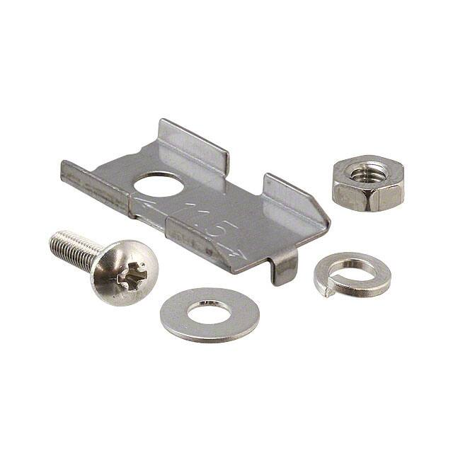
MS-GXL8-4
Mounting bracket for GX-8 type
MS-GXL15
Mounting bracket for GX-15 type
MS-A15F
For GX-FL15□(-P)
MS-A15H
For GX-HL15□(-P)
MS-GX8-1×10
10 pcs. per set
Screw is not
attached.
· MS-GL6-1
· MS-GL6-2
Mounting example when
mounted onto a steel or
stainless steel plate
· MS-A15F
· MS-A15H
Screw is not
attached.
· MS-GXL8-4
1pc. each of M3
(length: 12 mm 0.472 in)
truss head screw, nut,
spring washer and plain
washer is attached.
Mounting sleeve for GX-8 type
Screw, nut, bracket of GXL-8 series can be used by inserting
the bracket into the mounting hole of GX-8 type when replacing
3-wire type GXL-8 series (discontinued model) with GX-8 type.
Aluminum sheet
Screw is not
attached.
· MS-GXL15
Screw is not
attached.
�Rectangular-shaped Inductive Proximity Sensor
GX-F/H SERIES
SPECIFICATIONS
GX-6 type
Model No.
(Note 2)
Type
Item
NPN output
PNP output
Front sensing
GX-F6A(I)
GX-F6B(I)
GX-F6A(I)-P
GX-F6B(I)-P
Top sensing
GX-H6A(I)
GX-H6B(I)
GX-H6A(I)-P
GX-H6B(I)-P
CE marking directive compliance
EMC Directive, RoHS Directive
Max. operation distance (Note 3)
1.6 mm 0.063 in ± 8 %
Stable sensing range (Note 3)
0 to 1.3 mm 0 to 0.051 in
Iron sheet 12 × 12 × t 1 mm 0.472 × 0.472 × t 0.039 in
Standard sensing object
Hysteresis
20 % or less of operation distance (with standard sensing object)
Repeatability
Along sensing axis, perpendicular to sensing axis: 0.04 mm 0.002 in or less
+10
Supply voltage
12 to 24 V DC –15 % Ripple P-P 10 % or less
Current consumption
15 mA or less
NPN open-collector transistor
PNP open-collector transistor
• Maximum sink current: 100 mA
• Maximum source current: 100 mA
• Applied voltage: 30 V DC or less (between output and 0 V)
• Applied voltage: 30 V DC or less (between output and +V)
• Residual voltage: �2 V or less (at 100 mA sink current)
• Residual voltage: �2 V or less (at 100 mA source current)
Output
Utilization category
Output operation
DC-12 or DC-13
Normally open
Normally closed
Operation indicator
Environmental resistance
3 (Industrial environment)
Protection
IP68 (IEC), IP68G (Note 4, 5)
–25 to +70 °C –13 to +158 °F, Storage: – 40 to +85 °C – 40 to +185 °F
Ambient humidity
Voltage withstandability
Normally closed
Orange LED (lights up when the output is ON)
Pollution degree
Ambient temperature
Normally open
400 Hz
Max. response frequency
35 to 85 % RH, Storage: 35 to 95 % RH
1,000 V AC for one min. between all supply terminals connected together and enclosure
Insulation resistance
50 MΩ, or more, with 500 V DC megger between all supply terminals connected together and enclosure
Vibration resistance
10 to 500 Hz frequency, 3 mm 0.118 in double amplitude (Max. 20 G) in X, Y and Z directions for two hours each
Shock resistance
Sensing
range
variation
10,000 m/s2 acceleration (1,000 G approx.) in X, Y and Z directions three times each
Temperature characteristics
Over ambient temperature range –25 to +70 °C –13 to +158 °F: Within ± 8 % of sensing range at +23 °C +73 °F
Voltage characteristics
Within ±2 % for –15 % fluctuation of the supply voltage
+10
Material
Cable
Cable extension
Net weight
Enclosure: PBT, Indicator part: Polyester
0.15 mm 3-core oil, heat and cold resistant cabtyre cable, 1 m 3.281 ft long
2
Extension up to total 100 m 328.084 ft is possible with 0.3 mm2, or more, cable.
15 g approx.
Notes: 1) Where measurement conditions have not been specified precisely, the conditions used were an ambient temperature of +23 °C +73 °F.
2) “ I ” in the model No. indicates a different frequency type.
3) �The maximum operation distance stands for the maximum distance for which the sensor can detect the standard sensing object.
The stable sensing range stands for the sensing range for which the sensor can stably detect the standard sensing object even if there is an ambient
temperature drift and/or supply voltage fluctuation.
4) �Panasonic Industrial Devices SUNX’s IP68 test method
1 Immerse at 0 m below 0 °C +32 °F water surface and leave for 30 min. Then, immerse at 0 m below +70 °C +158 °F water surface and leave for 30 min.
2 Regard the heat shock test in 1 as one cycle and perform 20 cycles.
3 Leave in water at a depth of 1 m 3.281 ft in water for 500 hours.
4 After tests 1 to 3 , insulation resistance, voltage withstandability, current consumption, and sensing ranges must meet the standard values.
5) �If using the sensor in an environment where cutting oil droplets splatter, the sensor may be deteriorated due to added substances in the oil.
Please check the resistivity of the sensor against the cutting oil you are using beforehand.
7
�8
Rectangular-shaped Inductive Proximity Sensor
GX-F/H SERIES
SPECIFICATIONS
GX-8 type
Model No.
(Note 2)
Type
Item
NPN output
PNP output
Front sensing
GX-F8A(I)
GX-F8B(I)
GX-F8A(I)-P
GX-F8B(I)-P
Top sensing
GX-H8A(I)
GX-H8B(I)
GX-H8A(I)-P
GX-H8B(I)-P
CE marking directive compliance
EMC Directive, RoHS Directive
Max. operation distance (Note 3)
2.5 mm 0.098 in ± 8 %
Stable sensing range (Note 3)
0 to 2.1 mm 0 to 0.083 in
Standard sensing object
Iron sheet 15 × 15 × t 1 mm 0.591 × 0.591 × t 0.039 in
Hysteresis
20 % or less of operation distance (with standard sensing object)
Repeatability
Along sensing axis, perpendicular to sensing axis: 0.04 mm 0.002 in or less
+10
Supply voltage
12 to 24 V DC –15 % Ripple P-P 10 % or less
Current consumption
15 mA or less
NPN open-collector transistor
PNP open-collector transistor
• Maximum sink current: 100 mA
• Maximum source current: 100 mA
• Applied voltage: 30 V DC or less (between output and 0 V)
• Applied voltage: 30 V DC or less (between output and +V)
• Residual voltage: �2 V or less (at 100 mA sink current)
• Residual voltage: �2 V or less (at 100 mA source current)
Output
Utilization category
Output operation
DC-12 or DC-13
Normally open
Normally closed
Max. response frequency
Operation indicator
Environmental resistance
Pollution degree
Protection
Ambient temperature
Ambient humidity
Voltage withstandability
Normally open
Normally closed
500 Hz
Orange LED (lights up when the output is ON)
3 (Industrial environment)
IP68 (IEC), IP68G (Note 4, 5)
–25 to +70 °C –13 to +158 °F, Storage: – 40 to +85 °C – 40 to +185 °F
35 to 85 % RH, Storage: 35 to 95 % RH
1,000 V AC for one min. between all supply terminals connected together and enclosure
Insulation resistance
50 MΩ, or more, with 500 V DC megger between all supply terminals connected together and enclosure
Vibration resistance
10 to 500 Hz frequency, 3 mm 0.118 in double amplitude (Max. 20 G) in X, Y and Z directions for two hours each
Shock resistance
Sensing
range
variation
Temperature characteristics
Over ambient temperature range –25 to +70 °C –13 to +158 °F: Within ± 8 % of sensing range at +23 °C +73 °F
Voltage characteristics
Within ±2 % for –15 % fluctuation of the supply voltage
Material
Cable
Cable extension
Net weight
10,000 m/s2 acceleration (1,000 G approx.) in X, Y and Z directions three times each
+10
Enclosure: PBT, Indicator part: Polyester
0.15 mm2 3-core oil, heat and cold resistant cabtyre cable, 1 m 3.281 ft long
Extension up to total 100 m 328.084 ft is possible with 0.3 mm2, or more, cable.
Front sensing type: 15 g approx., Top sensing type: 20 g approx..
Notes: 1) Where measurement conditions have not been specified precisely, the conditions used were an ambient temperature of +23 °C +73 °F.
2) “ I ” in the model No. indicates a different frequency type.
3) The maximum operation distance stands for the maximum distance for which the sensor can detect the standard sensing object.
The stable sensing range stands for the sensing range for which the sensor can stably detect the standard sensing object even if there is an ambient
temperature drift and/or supply voltage fluctuation.
4) Panasonic Industrial Devices SUNX’s IP68 test method
1 Immerse at 0 m below 0 °C +32 °F water surface and leave for 30 min. Then, immerse at 0 m below +70 °C +158 °F water surface and leave for 30 min.
2 Regard the heat shock test in 1 as one cycle and perform 20 cycles.
3 Leave in water at a depth of 1 m 3.281 ft in water for 500 hours.
4 After tests 1 to 3 , insulation resistance, voltage withstandability, current consumption, and sensing ranges must meet the standard values.
5) If using the sensor in an environment where cutting oil droplets splatter, the sensor may be deteriorated due to added substances in the oil.
Please check the resistivity of the sensor against the cutting oil you are using beforehand.
�Rectangular-shaped Inductive Proximity Sensor
GX-F/H SERIES
SPECIFICATIONS
GX-12 type
Item
Model No.
(Note 2)
Type
NPN output
PNP output
Front sensing
GX-F12A(I)
GX-F12B(I)
GX-F12A(I)-P
GX-F12B(I)-P
Top sensing
GX-H12A(I)
GX-H12B(I)
GX-H12A(I)-P
GX-H12B(I)-P
CE marking directive compliance
EMC Directive, RoHS Directive
Max. operation distance (Note 3)
4.0 mm 0.157 in ± 8 %
Stable sensing range (Note 3)
0 to 3.3 mm 0 to 0.130 in
Standard sensing object
Iron sheet 20 × 20 × t 1 mm 0.787 × 0.787 × t 0.039 in
Hysteresis
20 % or less of operation distance (with standard sensing object)
Repeatability
Along sensing axis, perpendicular to sensing axis: 0.04 mm 0.002 in or less
+10
Supply voltage
12 to 24 V DC –15 % Ripple P-P 10 % or less
Current consumption
15 mA or less
NPN open-collector transistor
PNP open-collector transistor
• Maximum sink current: 100 mA
• Maximum source current: 100 mA
• Applied voltage: 30 V DC or less (between output and 0 V)
• Applied voltage: 30 V DC or less (between output and +V)
• Residual voltage: �2 V or less (at 100 mA sink current)
• Residual voltage: �2 V or less (at 100 mA source current)
Output
Utilization category
Output operation
Max. response frequency
Operation indicator
Environmental resistance
Pollution degree
Protection
Ambient temperature
Ambient humidity
Voltage withstandability
DC-12 or DC-13
Normally open
Normally closed
Normally open
Normally closed
500 Hz
Orange LED (lights up when the output is ON)
3 (Industrial environment)
IP68 (IEC), IP68G (Note 4, 5)
–25 to +70 °C –13 to +158 °F, Storage: – 40 to +85 °C – 40 to +185 °F
35 to 85 % RH, Storage: 35 to 95 % RH
1,000 V AC for one min. between all supply terminals connected together and enclosure
Insulation resistance
50 MΩ, or more, with 500 V DC megger between all supply terminals connected together and enclosure
Vibration resistance
10 to 500 Hz frequency, 3 mm 0.118 in double amplitude (Max. 20 G) in X, Y and Z directions for two hours each
Shock resistance
Sensing
range
variation
Temperature characteristics
Over ambient temperature range –25 to +70 °C –13 to +158 °F: Within ±8 % of sensing range at +23 °C +73 °F
Voltage characteristics
Within ±2 % for +10
–15 % fluctuation of the supply voltage
Material
Cable
Cable extension
Net weight
10,000 m/s2 acceleration (1,000 G approx.) in X, Y and Z directions three times each
Enclosure: PBT, Indicator part: Polyester
0.15 mm2 3-core oil, heat and cold resistant cabtyre cable, 1 m 3.281 ft long
Extension up to total 100 m 328.084 ft is possible with 0.3 mm2, or more, cable.
Front sensing type: 20 g approx., Top sensing type: 20 g approx..
Notes: 1) Where measurement conditions have not been specified precisely, the conditions used were an ambient temperature of +23 °C +73 °F.
2) “ I ” in the model No. indicates a different frequency type.
3) The maximum operation distance stands for the maximum distance for which the sensor can detect the standard sensing object.
The stable sensing range stands for the sensing range for which the sensor can stably detect the standard sensing object even if there is an ambient
temperature drift and/or supply voltage fluctuation.
4) Panasonic Industrial Devices SUNX’s IP68 test method
1 Immerse at 0 m below 0 °C +32 °F water surface and leave for 30 min. Then, immerse at 0 m below +70 °C +158 °F water surface and leave for 30 min.
2 Regard the heat shock test in 1 as one cycle and perform 20 cycles.
3 Leave in water at a depth of 1 m 3.281 ft in water for 500 hours.
4 After tests 1 to 3 , insulation resistance, voltage withstandability, current consumption, and sensing ranges must meet the standard values.
5) If using the sensor in an environment where cutting oil droplets splatter, the sensor may be deteriorated due to added substances in the oil.
Please check the resistivity of the sensor against the cutting oil you are using beforehand.
9
�10
Rectangular-shaped Inductive Proximity Sensor
GX-F/H SERIES
SPECIFICATIONS
GX-15 type
NPN output
Model No.
(Note 2)
Type
Item
Long sensing range
Front sensing GX-F15A(I)
Top sensing
PNP output
GX-F15B(I)
Long sensing range
GX-FL15A(I) GX-FL15B(I) GX-F15A(I)-P GX-F15B(I)-P GX-FL15A(I)-P GX-FL15B(I)-P
GX-H15A(I) GX-H15B(I) GX-HL15A(I) GX-HL15B(I) GX-H15A(I)-P GX-H15B(I)-P GX-HL15A(I)-P GX-HL15B(I)-P
EMC Directive, RoHS Directive
CE marking directive compliance
Max. operation distance (Note 3)
5.0 mm 0.197 in ± 8 %
8.0 mm 0.315 in ± 8 % (Note 4)
5.0 mm 0.197 in ± 8 %
8.0 mm 0.315 in ± 8 % (Note 4)
Stable sensing range (Note 3)
0 to 4.2 mm 0 to 0.165 in
0 to 6.7 mm 0 to 0.264 in (Note 4)
0 to 4.2 mm 0 to 0.165 in
0 to 6.7 mm 0 to 0.264 in (Note 4)
Standard sensing object
Iron sheet 20 × 20 × t 1 mm
0.787× 0.787 × t 0.039 in
Iron sheet 30 × 30 × t 1 mm
1.181 × 1.181 × t 0.039 in
Iron sheet 20 × 20 × t 1 mm
0.787 × 0.787 × t 0.039 in
Iron sheet 30 × 30 × t 1 mm
1.181 × 1.181 × t 0.039 in
Hysteresis
20 % or less of operation distance (with standard sensing object)
Repeatability
Along sensing axis, perpendicular to sensing axis: 0.04 mm 0.002 in or less
+10
Supply voltage
12 to 24 V DC –15 % Ripple P-P 10 % or less
Current consumption
15 mA or less
NPN open-collector transistor
PNP open-collector transistor
• Maximum sink current: 100 mA
• Maximum source current: 100 mA
• Applied voltage: 30 V DC or less (between output and 0 V)
• Applied voltage: 30 V DC or less (between output and +V)
• Residual voltage: �2 V or less (at 100 mA sink current)
• Residual voltage: �2 V or less (at 100 mA source current)
Output
Utilization category
Output operation
Max. response frequency
Operation indicator
Environmental resistance
Pollution degree
Protection
Ambient temperature
Ambient humidity
Voltage withstandability
DC-12 or DC-13
Normally open Normally closed Normally open Normally closed Normally open Normally closed Normally open Normally closed
250 Hz
150 Hz (Note 5)
250 Hz
150 Hz (Note 5)
Orange LED (lights up when the output is ON)
3 (Industrial environment)
IP68 (IEC), IP68G (Note 6, 7)
–25 to +70 °C –13 to +158 °F, Storage: – 40 to +85 °C – 40 to +185 °F
35 to 85 % RH, Storage: 35 to 95 % RH
1,000 V AC for one min. between all supply terminals connected together and enclosure
Insulation resistance
50 MΩ, or more, with 500 V DC megger between all supply terminals connected together and enclosure
Vibration resistance
10 to 500 Hz frequency, 3 mm 0.118 in double amplitude (Max. 20 G) in X, Y and Z directions for two hours each
Shock resistance
Sensing
range
variation
Temperature characteristics
Over ambient temperature range –25 to +70 °C –13 to +158 °F: Within ± 8 % of sensing range at +23 °C +73 °F
Voltage characteristics
Within ±2 % for –15 % fluctuation of the supply voltage
Material
Cable
Cable extension
Net weight
10,000 m/s2 acceleration (1,000 G approx.) in X, Y and Z directions three times each
+10
Enclosure: PBT, Indicator part: Polyester
0.15 mm2 3-core oil, heat and cold resistant cabtyre cable, 1 m 3.281 ft long
Extension up to total 100 m 328.084 ft is possible with 0.3 mm2, or more, cable.
20 g approx.
Notes: 1) Where measurement conditions have not been specified precisely, the conditions used were an ambient temperature of +23 °C +73 °F.
2) “ I ” in the model No. indicates a different frequency type.
3) �The maximum operation distance stands for the maximum distance for which the sensor can detect the standard sensing object.
The stable sensing range stands for the sensing range for which the sensor can stably detect the standard sensing object even if there is an ambient
temperature drift and/or supply voltage fluctuation.
4) �This is the numerical value which the sensor mount onto an insulator. When mounted onto a steel or stainless steel plate, insert the optional
aluminum sheet between the sensor and the plate.
is the numerical value which the sensor mount onto an insulator. When mounted onto a metallic plate, max. response frequency will decrease.
5) This
�
6) �Panasonic Industrial Devices SUNX’s IP68 test method
1 Immerse at 0 m below 0 °C +32 °F water surface and leave for 30 min. Then, immerse at 0 m below +70 °C +158 °F water surface and leave for 30 min.
2 Regard the heat shock test in 1 as one cycle and perform 20 cycles.
3 Leave in water at a depth of 1 m 3.281 ft in water for 500 hours.
4 After tests 1 to 3 , insulation resistance, voltage withstandability, current consumption, and sensing ranges must meet the standard values.
7) �If using the sensor in an environment where cutting oil droplets splatter, the sensor may be deteriorated due to added substances in the oil.
Please check the resistivity of the sensor against the cutting oil you are using beforehand.
�Rectangular-shaped Inductive Proximity Sensor
GX-F/H SERIES
I/O CIRCUIT DIAGRAMS
NPN output type
I/O circuit diagram
Wiring diagram
Sensor circuit
Color code
Tr
D1
(Brown) +V
D2
(Black) Output
(Note)
ZD
Brown
Load
100 mA max.
+
–
Black
12 to 24V DC
+10
–15 %
Load
+
–
12 to 24V DC
+10
–15 %
Blue
(Blue) 0 V
Internal circuit
Users’ circuit
Symbols … D1: Reverse supply polarity protection diode
D2: Reverse output polarity protection diode
ZD: Surge absorption zener diode
Tr : NPN output transistor
Note: The output does not incorporate a short-circuit protection circuit.
Do not connect it directly to a power supply or a capacitive load.
PNP output type
I/O circuit diagram
Wiring diagram
Color code
Brown
Sensor circuit
(Brown) +V
ZD
Tr
100 mA max.
D2
(Black) Output
(Note)
D1
(Blue) 0 V
Internal circuit
Load
+
–
12 to 24V DC
+10
–15 %
+
Black
Blue
Load
Users’ circuit
Symbols … D1: Reverse supply polarity protection diode
D2: Reverse output polarity protection diode
ZD: Surge absorption zener diode
Tr : PNP output transistor
Note: The output does not incorporate a short-circuit protection circuit. �
Do not connect it directly to a power supply or a capacitive load.
–
12 to 24V DC
+10
–15 %
11
�12
Rectangular-shaped Inductive Proximity Sensor
GX-F/H SERIES
SENSING CHARACTERISTICS (TYPICAL)
GX-6 type
4
0.157 Standard sensing object
Iron sheet 12 × 12 × t 1 mm
0.472 × 0.472 × t 0.039 in
ℓ
3
0.118
Front sensing
Correlation between sensing object size and sensing range
Standard sensing object
Iron sheet 12 × 12 × t 1 mm
0.472 × 0.472 × t 0.039 in
ℓ
L
L
Top sensing
2
0.079
1
0.039
0
4
0.157
4
0.157
Sensing range L (mm in)
Setting distance L (mm in)
Sensing field
Sensing object Sensing object
a × a mm a × a in a × a mm a × a in
t 1mm L
L
t 1mm
t 0.039 in
t 0.039 in
Top sensing
3
0.118
Front sensing
Stainless steel
(SUS304)
2
0.079
Iron
1
0.039
Aluminum
Brass
2
0
2
4
0.079
0.079
0.157
Left
Center
Right
Operating point ℓ (mm in)
0
As the sensing object size becomes smaller than
the standard size (iron sheet 12 × 12 × t 1 mm
0.472 × 0.472 × t 0.039 in), the sensing range
shortens as shown in the left figure.
5
10
15
0.197
0.394
0.591
Sensing object side
length a (mm in)
20
0.787
GX-8 type
4
0.157 Standard sensing object Standard sensing object
Iron sheet 15 × 15 × t 1 mm Iron sheet 15 × 15 × t 1 mm
0.591 × 0.591 × t 0.039 in 0.591 × 0.591 × t 0.039 in
ℓ
ℓ
L
3
L
0.118 Front sensing
Top sensing
2
0.079
1
0.039
0
4
0.157
Correlation between sensing object size and sensing range
4
0.157
Sensing object
Sensing object
a × a mm a × a in
a × a mm a × a in
t 1 mm
t 1 mm
L
t 0.039 in L
t 0.039 in
3
Top sensing
0.118
Front sensing
Iron
2
Stainless steel
0.079
(SUS304)
Brass
1
Aluminum
0.039
Sensing range L (mm in)
Setting distance L (mm in)
Sensing field
0
2
0
2
4
0.079
0.079
0.157
Left
Center
Right
Operating point ℓ (mm in)
5
10
15
0.197
0.394
0.591
Sensing object side
length a (mm in)
As the sensing object size becomes smaller than
the standard size (iron sheet 15 × 15 × t 1 mm
0.591 × 0.591 × t 0.039 in), the sensing range
shortens as shown in the left figure.
20
0.787
GX-12 type
8
0.315 Standard sensing object Standard sensing object
Iron sheet 20 × 20 × t 1 mm Iron sheet 20 × 20 × t 1 mm
0.787 × 0.787 × t 0.039 in 0.787 × 0.787 × t 0.039 in
ℓ
ℓ
6
L
L
0.236
Top sensing
Front sensing
4
0.157
2
0.079
0
10
0.394
Correlation between sensing object size and sensing range
8
Sensing
0.315 Sensing object a × a mm a × a in object
a × a mm
t 1 mm
L
t 0.039 in a × a in
6 Front sensing
L
t 1 mm
0.236
Top sensing t 0.039 in
Iron
4
Stainless steel
0.157
(SUS304)
Sensing range L (mm in)
Setting distance L (mm in)
Sensing field
Brass
2
0.079
5
0
5
10
0.197
0.197
0.394
Left
Center
Right
Operating point ℓ (mm in)
As the sensing object size becomes smaller than
the standard size (iron sheet 20 × 20 × t 1 mm
0.787 × 0.787 × t 0.039 in), the sensing range
shortens as shown in the left figure.
Aluminum
0
10
20
30
0.394
0.787
1.181
Sensing object side
length a (mm in)
40
1.575
GX-15 type
8
0.315 Standard sensing object Standard sensing object
Iron sheet 20 × 20 × t 1 mm Iron sheet 20 × 20 × t 1 mm
0.787 × 0.787 × t 0.039 in
0.787 × 0.787 × t 0.039 in
ℓ
ℓ
Front
6
L
L
sensing
Top
sensing
0.236
4
0.157
8
0.315
6
0.236
4
0.157
2
0.079
0
10
0.394
Correlation between sensing object size and sensing range
Sensing range L (mm in)
Setting distance L (mm in)
Sensing field
2
0.079
5
0
5
10
0.197
0.197
0.394
Left
Center
Right
Operating point ℓ (mm in)
0
L
Sensing object Sensing object a × a mm a × a in
a × a mm a × a in
L
t 1mm t 0.039 in
t 1mm
Top sensing
t 0.039 in
Front
Iron
sensing
Stainless steel
(SUS304)
Brass
Aluminum
10
20
30
0.394
0.787
1.181
Sensing object side
length a (mm in)
40
1.575
As the sensing object size becomes smaller than
the standard size (iron sheet 20 × 20 × t 1 mm
0.787 × 0.787 × t 0.039 in), the sensing range
shortens as shown in the left figure.
�Rectangular-shaped Inductive Proximity Sensor
GX-F/H SERIES
13
SENSING CHARACTERISTICS (TYPICAL)
GX-15 (Long sensing range) type
10
0.394
Correlation between sensing object size and sensing range
Standard sensing object Standard sensing object
Iron sheet 30 × 30 × t 1 mm Iron sheet 30 × 30 × t 1 mm
1.181 × 1.181 × t 0.039 in 1.181 × 1.181 × t 0.039 in
ℓ
Top
sensing
L
Sensing object
a × a mm a × a in
ℓ
Front
sensing
Sensing range L (mm in)
Setting distance L (mm in)
Sensing field
L
5
0.197
0
10
0.394
10
L
0.394
t 1mm
t 0.039 in
Front sensing
Sensing object
a × a mm a × a in
L
t 1mm t 0.039 in
Top sensing Iron
As the sensing object size becomes smaller than
the standard size (iron sheet 30 × 30 × t 1 mm
1.181 × 1.181 × t 0.039 in), the sensing range
shortens as shown in the left figure.
Stainless steel
(SUS304)
5
0.197
Brass
Aluminum
0
0
5
5
10
0.197
0.197
0.394
Left
Center
Right
Operating point ℓ (mm in)
10
20
30
0.394
0.787
1.181
Sensing object side
length a (mm in)
40
1.575
PRECAUTIONS FOR PROPER USE
• Never use this product as a sensing device
for personnel protection.
• In case of using sensing devices for
personnel protection, use products which
meet laws and standards, such as OSHA,
ANSI or IEC etc., for personnel protection
applicable in each region or country.
Mounting
GX-6 type
• Use the optional sensor mounting bracket when
installing.
M3 pan head screw
(Purchase separately.)
Sensor mounting bracket
MS-GX6-1 (Optional)
Cable
Hook
Groove
M3 × 0.5 mm 0.020 in
tapped hole (Depth: 8 mm
0.315 in or more) or
ø3.4 mm ø0.134 in thru-hole
22 mm 0.866 in
ø2.4 mm
ø0.094 in hole
(Depth: 3 mm
0.118 in or more)
No nuts, washers, or
spring washers are
attached with the
product.
Purchase separately.
• To mount the sensor with a nut, the mounting hole
diameter should be ø3.4 mm ø0.134 in.
Sensor mounting bracket
MS-GL6-1 (Optional) ø2.4 mm
0.094 in hole
(Depth: 3 mm
0.118 in or more)
M3 × 0.5 mm 0.020 in
tapped holes or
ø3.4 mm ø0.134 in thru-holes
• The tightening torque
should be 0.7 N·m or less.
• To mount the sensor with
a nut, the mounting hole
diameter should be
ø3.4 mm ø0.134 in.
Further, the hole in which
the boss is inserted should
be ø2.5 mm ø0.098 in and
3 mm 0.118 in, or more,
deep.
M3 (length 12 mm 0.472 in) truss head
screw (Accessory for MS-GXL8-4)
Sensor mounting bracket
MS-GXL8-4 (Optional)
M3 × 0.5 mm 0.020 in tapped hole
(Depth: 8 mm 0.315 in or more)
or ø3.4 mm ø0.134 in thru-hole
11.5 mm 0.453 in
The nut, washer, and spring
washer are attached with the
MS-GXL8-4.
ø2.4 mm ø0.094 in hole
(Depth: 3 mm 0.118 in or more)
M3 × 0.5 mm 0.020 in
tapped hole or
ø3.4 mm ø0.134 in thru-holes
No nuts, washers, or
spring washers are
attached with the
product.
Purchase separately.
M3 (length 12 mm 0.472 in or more)
pan head screw
(Purchase separately.)
M3 × 0.5 mm 0.020 in tapped hole
(Depth: 10 mm 0.394 in or more)
or ø3.4 mm ø0.134 in thru-hole
16 mm 0.630 in
No nuts, washers, or spring washers
are attached with the product.
Purchase separately.
ø2.5 mm ø0.098 in hole
(Depth: 3 mm 0.118 in or more)
GX-15 type
• The tightening torque
should be 1 N·m or less.
• To mount the sensor with
a nut, the mounting hole
diameter should be
ø3.4 mm ø0.134 in.
M3 pan head screws or
truss head screws
Do not use flat head
screws.
M3 × 0.5 mm 0.020 in
tapped holes or ø3.4 mm
ø0.134 in thru-holes
9 mm
0.354 in
Sensor mounting bracket
MS-GL6-2 (Optional)
10 mm
0.394 in
No nuts, washers, or
spring washers are
attached with the
product.
Purchase separately.
• Make sure to use a M3
(length: 12 mm 0.472 in or
more) truss head screw
(accessory for MS-GXL8-4).
The tightening torque
should be 0.7 N·m or less.
Do not use a flat head
screw or a pan head
screw.
M3 pan head screw
(Purchase separately.)
M3 pan head screws
(Purchase separately.)
13.6 mm
0.535 in
GX-12 type
• To mount the sensor with
a nut, the mounting hole
diameter should be
ø3.4 mm ø0.134 in.
1 Insert the sensor into the
bracket as shown on the
right.
2 Push the sensor until the
bracket hook is lodged in
the groove on the upper
portion of the sensor.
3 Fix the bracket in place
with M3 pan head screw.
GX-8 type
No nuts, washers, or spring washers
are attached with the product.
Purchase separately.
MS-GXL15
(Sensor mounting bracket)
• When installing the long
sensing range type on iron
or stainless steel plate, put
the optional aluminum sheet
in between the sensor and
the plate.
Aluminum sheet (Optional)
• MS-A15F
• MS-A15H
�14
GX-F/H SERIES
Rectangular-shaped Inductive Proximity Sensor
PRECAUTIONS FOR PROPER USE
Influence of surrounding metal
Sensing range
• When there is a metal near the sensor, keep the minimum
separation distance specified below.
Front sensing type
Metal
B
Metal
A
Metal
C
C
GX-F6 type GX-F8 type GX-F12 type GX-F15 type GX-FL15 type
A
6 mm 0.236 in
7.4 mm 0.291 in 7.1 mm 0.280 in
(Note 1)
B
8 mm 0.315 in
8 mm 0.315 in 20 mm 0.787 in 20 mm 0.787 in 30 mm 1.181 in
C
3 mm 0.118 in
3 mm 0.118 in
7 mm 0.276 in
8 mm 0.315 in
(Note 2)
8 mm 0.315 in
7 mm 0.276 in 10 mm 0.394 in
Notes: 1) When using MS-GX6-1 (recommended mounting bracket, optional),
the distance “A” including the thickness of mounting bracket will be
6.4 mm 0.252 in.
2) The GXL-FL15 type should be mounted on an insulator. To mount
it on an iron or stainless steel, use the enclosed aluminum sheet.
Top sensing type
Metal
Metal
Aluminum
0.48 approx. 0.48 approx. 0.53 approx. 0.45 approx. 0.43 approx. 0.48 approx.
Wiring
• The output does not incorporate a short-circuit protection
circuit. Do not connect it directly to a power supply or a
capacitive load.
• Do not use during the initial transient time (50 ms) after
the power supply is switched on.
G
Metal
F
GX-H6 type GX-H8 type GX-H12 type GX-H15 type GX-HL15 type
3 mm 0.118 in
4 mm 0.157 in
7 mm 0.276 in
6 mm 0.236 in 12 mm 0.472 in
10 mm 0.394 in 10 mm 0.394 in 20 mm 0.787 in 20 mm 0.787 in 30 mm 1.181 in
10 mm 0.394 in
(Note)
F
2 mm 0.079 in
3 mm 0.118 in
3 mm 0.118 in
0 mm
G
2 mm 0.079 in
3 mm 0.118 in
3 mm 0.118 in
3 mm 0.118 in 10 mm 0.394 in
0 in
Note: �When GX-HL15 type is mounted on an insulator or seated on the
enclosed aluminum sheet, the distance “F” can be zero.
Mutual interference prevention
• When two or more sensors are installed in parallel or face
to face, keep the minimum separation distance specified
below to avoid mutual interference.
H
J
GX-F6
GX-H6
Between “I” type
0 mm
(Note 2)
and non “I” type
Between two “I” types 13 mm
or two non “I” types
0.512 in
GX-F8
GX-H8
Between “I” type
and non “I” type
type
Between two “I” types 20 mm 35 mm
or two non “I” types
0.787 in 1.378 in
GX-F12
GX-H12
Between “I” type
and non “I” type
0 mm 25 mm
(Note 2) 0.984 in
Between two “I” types
or two non “I” types
Between “I” type
and non “I” type
Between two “I” types
or two non “I” types
Between “I” type
and non “I” type
Between two “I” types
or two non “I” types
25 mm 50 mm
0.984 in 1.969 in
type
type
GX-F15
GX-H15
type
GX-FL15
GX-HL15
type
Iron
1
1
1
1
1
1
Stainless steel
0.76 approx. 0.76 approx. 0.79 approx. 0.68 approx. 0.70 approx. 0.76 approx.
(SUS304)
Brass
0.50 approx. 0.50 approx. 0.56 approx. 0.47 approx. 0.45 approx. 0.50 approx.
Others
G
Metal
E
Correction coefficient
Model GX-F6 GX-F8 GX-F12 GX-F15
No. GX-H6 GX-H8 GX-H12 GX-H15 GX-FL15 GX-HL15
type
type
type
type
type
type
Metal
D
E
D
• The sensing range is specified for the standard sensing
object. With a non-ferrous metal, the sensing range is
obtained by multiplying with the correction coefficient
specified below. Further, the sensing range also changes
if the sensing object is smaller than the standard sensing
object or if the sensing object is plated.
Front sensing
15 mm
0.591 in
25 mm
0.984 in
0 mm 15 mm
(Note 2) 0.591 in
0 mm 25 mm
(Note 2) 0.984 in
H
H
J
Top sensing
45 mm 70 mm
1.772 in 2.756 in
0 mm 25 mm
(Note 2) 0.984 in
H
J
110 mm 170 mm
3.059 in 6.693 in
Notes: 1) “I” in the model No. specifies
the different frequency type.
2) Close mounting is possible for up to two sensors.
When mounting three sensors or more at an equal spacing, align
the model with “I” and the model without “I” alternately. The minimum
value of dimension “H” should be as given below.
GX-F6/H6 type: 3.5 mm 0.138 in
GX-F8/H8 type: 6 mm 0.236 in
GX-F12/H12 type: 6.5 mm 0.256 in
GX-F15/H15 type: 15 mm 0.591 in
GX-FL15/HL15 type: 47.5 mm 1.870 in
�Rectangular-shaped Inductive Proximity Sensor
DIMENSIONS (Unit: mm in)
The CAD data can be downloaded from our website.
GX-F6□
GX-H6□
Sensor
Sensor
Sensing direction
3
0.118
6
0.236
11
0.433
6
0.236
24.5
0.965
0.5
0.020
15
GX-F/H SERIES
ø3 ø0.118 cable,
1 m 3.281 ft long
Sensing direction 0.5
0.020
2.6
0.102
6
0.236
Operation indicator
(Orange)
ø3 ø0.118 cable,
1 m 3.281 ft long
6
0.236
25
0.984
0.5
2.5 0.020
0.098
11.5
0.453
0.5
6 0.020
3
0.118 0.236
6
0.236
Operation indicator (Orange)
GX-F8□
GX-H8□
Sensor
Sensor
Operation indicator (Orange)
7.4
0.291
8
0.315
Sensing
direction
23
22.5 11.5
0.906 0.886 0.453
6.5
0.256
5.4
0.213
1
0.039
Operation indicator
(Orange)
Sensing
direction
2.95
0.116
8.55
0.337
ø9 ø0.354
7.7
0.303
3.7
0.146
ø3.1 ø0.12
mounting hole
9.75
0.384
8.2 0.323
ø3 ø0.118 cable,
1 m 3.281 ft long
5
0.197
6.3
0.248
2.65
0.104
8.6
0.339
3.85
R4.25
R0.167 0.152
5.4 0.213 6.3 0.248
ø3 ø0.118 cable,
18.5
1 m 3.281 ft long
0.728
6.8
2 0.079
0.268
2.4
0.095
9.1 0.358
8
0.315
5.3
0.209
GX-F12□
ø3.1 ø0.122 mounting hole
4.6
0.181
4.8 0.189 5.3 0.209
2.5
0.098
25
0.984
1
0.039
GX-H12□
Sensor
Sensor
Operation indicator
(Orange)
Sensing
direction
7.1
0.280
3.3 0.130
1.5 0.059
12
0.472
Sensing
direction
27.8 27 16
1.095 1.063 0.630
12
0.472
11.05
0.435
ø12.5 ø0.492
ø3.1 ø0.12
mounting hole
5 0.197
6.8
0.268
ø3 ø0.118 cable,
1 m 3.281 ft long
5.2
0.205
7.8
0.307
Operation indicator
(Orange)
12
0.472
5.5
0.217
ø2.3
ø0.091
16
0.630
ø2.3
ø0.091
31.5
1.240
20.5
0.807
ø3 ø0.118 cable,
1 m 3.281 ft long
1.5
0.059
16
0.630
27.4
1.079
2.5
0.098
4.4
0.173
3.1 5.8
0.12 0.228
Sensor
Operation indicator (Orange)
2-ø3.1 ø0.122 holes
ø15.5 ø0.610
7.8
0.307
ø15.5
ø0.610
5.3
0.209
16.5 15.65 14.15
0.650 0.616 0.557
Operation indicator (Orange)
2.8
0.110
2-ø3.1 ø0.122 holes
ø3 ø0.118 cable, 1 m 3.281 ft long
9
0.354
Sensing direction
8
0.315
3.7
0.146
6.2
0.244
6.5 0.256
GX-H(L)15□
9
0.354
15
0.591
14.15
0.557
ø6 ø0.236 screw seat,
1.4 0.055 deep
5.6
0.221
Sensor
Sensing
direction
ø3.1 ø0.122 mounting hole
22.2
0.874
2.8
0.110
GX-F(L)15□
7.5
0.295
6.8 0.268 7.8 0.307
8.65 0.341
4.8 0.189
3 0.118
R6.25 R0.246
13 12.5 12
0.512 0.492 0.472
12.4
0.488
ø6 ø0.236 screw seat,
0.8 0.032 deep
4.4 0.173
ø3 ø0.118 cable,
1 m 3.281 ft long
5.7
0.224
3
0.118
26
1.024
21.5
0.846
11.95
0.470
5.3
0.209
8.5
0.335
15
0.591
2.3
0.091
29.5
1.161
2.8
0.110
7.2
0.283
�16
Rectangular-shaped Inductive Proximity Sensor
GX-F/H SERIES
DIMENSIONS (Unit: mm in)
MS-GX6-1
Sensor mounting bracket for GX-6 type (Optional)
25.75
1.014
25.35
0.998
ø3.1
ø0.122
t 0.4
t 0.016
22
0.866
6.8
0.268
2.3
0.091
6.4
0.252
M3 × 0.5 0.020 tapped hole,
8 0.315 or more deep
(or ø3.4 ø0.134 thru-hole)
2
0.079
5.3
0.209
Mounting hole dimensions
3.2
0.126
6
0.236
5.5
0.217
5.6
0.220
19.6 0.772
(Note)
2-M3 × 0.5 0.020 tapped holes
(or 2-ø3.4 ø0.134 thru-holes)
t 0.4
t 0.016
Note: 20 mm 0.787 in with the sensor fitted.
Sensor mounting bracket for GX-6 type (Optional)
MS-GXL8-4 Sensor mounting bracket for GX-8 type (Optional)
Mounting hole dimensions
Mounting hole dimensions
3.2 × 3.8 0.126 × 0.150 oblong hole
3.2
0.126
5.5
0.217
5.6
t 0.4
1.5 0.220
13.2 0.520 t 0.016
0.059 (Note)
13.6
0.535
2-3.2 × 3.8 0.126 × 0.150 oblong holes
Material: Stainless steel (SUS301)
6
0.236
6
0.236
Sensor mounting bracket for GX-6 type (Optional)
6
0.236
ø2.4 ø0.094 hole,
3 0.118 or more deep
Material: Stainless steel (SUS304)
MS-GL6-2
MS-GL6-1
Mounting hole dimensions
22.2
(0.874
)
3.55
0.140
The CAD data can be downloaded from our website.
ø2.4 ø0.094 hole,
2.2 3 0.118 or more deep
0.087
10
0.394
2.3
0.091
9
0.354
M3 × 0.5 0.020 tapped hole
(or ø3.4 ø0.134 thru-hole)
(16.2) 15.8
(0.638) 0.622
Center of
2 sensing
0.079
2
0.079
0.3
0.012
(11.5)
3.3 (0.453)
0.130
t 0.4
t 0.016
ø2.4 ø0.094 hole,
3 0.118 or more deep
M3 × 0.5 0.020
tapped hole,
8 0.315 or more deep
(or ø3.4 ø0.134 thru-hole)
11.5
0.453
4.5 0.177
Material: Stainless steel (SUS301)
ø3.1 ø0.122 hole
Note: 13.4 mm 0.528 in with the sensor fitted.
Material: Stainless steel (SUS304)
1 pc. each of M3 (length 12 mm 0.472 in) truss head screw,
nut, spring washer and plain washer is attached.
MS-GXL15 Sensor mounting bracket for GX-15 type (Optional)
MS-A15F
MS-A15H
t2
t 0.079
14
0.551
9
0.354
2.5
0.098
7
0.276
Aluminum sheet (Optional)
30
1.181
2-ø3.2
ø0.126
2-3.2 × 5.1
0.126 × 0.201
oblong holes
4
0.157
2-M3 × 0.5 0.020 tapped holes
Material: Cold rolled carbon steel (SPCC)
1.9
0.075
9
0.354
21
0.827
(
39.5
1.555
MS-A15H:
30 1.181
)
t = 0.3 0.012
1.9
0.075
�Disclaimer
The applications described in the catalog are all intended for examples only. The purchase of our products described in the catalog shall not be
regarded as granting of a license to use our products in the described applications. We do NOT warrant that we have obtained some
intellectual properties, such as patent rights, with respect to such applications, or that the described applications may not infringe any
intellectual property rights, such as patent rights, of a third party.
Panasonic Industry Co., Ltd.
Industrial Device Business Division
7-1-1, Morofuku, Daito-shi, Osaka 574-0044, Japan
industrial.panasonic.com/ac/e/
ⓒ Panasonic Industry Co., Ltd.
Specifications are subject to change without notice.
Printed in Japan
2022.5
�