961
FIBER
SENSORS
ON/OFF Input Sensor Controller
NPS SERIES
Related Information
■■General terms and conditions.............. F-3
■■General precautions...................... P.1595
LASER
SENSORS
PHOTOELECTRIC
SENSORS
MICRO
PHOTOELECTRIC
SENSORS
AREA
SENSORS
SAFETY LIGHT
CURTAINS /
SAFETY COMPONENTS
PRESSURE /
FLOW
SENSORS
INDUCTIVE
PROXIMITY
SENSORS
PARTICULAR
USE SENSORS
SENSOR
OPTIONS
SIMPLE
WIRE-SAVING
UNITS
WIRE-SAVING
SYSTEMS
MEASUREMENT
SENSORS
panasonic.net/id/pidsx/global
STATIC
CONTROL
DEVICES
LASER
MARKERS
PLC
HUMAN MACHINE
INTERFACES
ENERGY
MANAGEMENT
SOLUTIONS
FA COMPONENTS
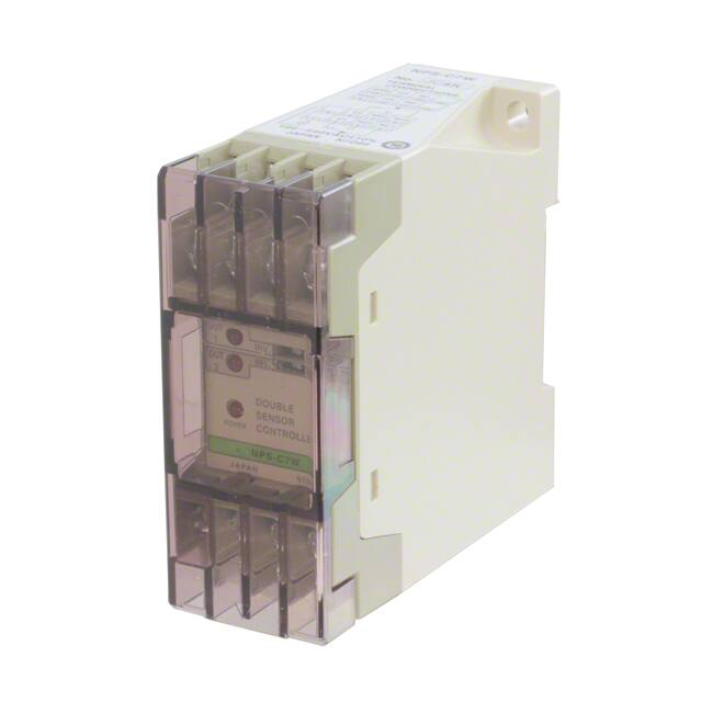
Multi-functional DIN rail mounting slim sensor controller
NPS-CT7
DIN rail mounting
Edge trigger
Mountable on 35 mm 1.378 in DIN rail by one-push.
It reduces mounting space and mounting operations.
Synchronized input is possible at either the rising or
the falling edge of the external synchronization signal.
With this, now only one controller suffices where earlier
two were required in applications, such as, detecting
presence of bottle caps.
MACHINE VISION
SYSTEMS
UV CURING
SYSTEMS
Example: Detecting presence of cap on bottle
35 mm 1.378 in
width DIN rail
• Using NPS-CT7
• Conventional method
Sensor for sensing
Sensor Mounting
Stand
Sensor
Checker
Sensor
Controller
Other Products
NPS
Two outputs: contact and non-contact NPS-C7, NPS-CT7
Output
Controller
External
synchronization
input
Controller
with timer
Useful for various applications because the controller
has two outputs, relay contact and NPN open-collector
transistor output.
Connects two sensors
NPS-C7W
Two sensors can be connected, and two independent
outputs are generated.
Sensor signal input
NPS-CT7
Output
External
synchronization
input
Synchronizing
sensor
Sensor signal
input
External
synchronization
input
Output
No cap
Cap present
Effective (condition for making output ON)
Ineffective
Effective
Ineffective (condition for disabling output)
5 μs approx.
ON
OFF
�ON/OFF Input Sensor Controller
NPS SERIES
ORDER GUIDE
FIBER
SENSORS
Appearance
Power supply
for sensor
Supply
voltage
Model No.
Two sensor
HighGeneral
connection performance
use
Type
962
12 V DC ±10 %
150 mA max.
NPS-C7
100-240 V AC
±10 %
NPS-CT7
12 V DC ±10 %
130 mA max.
12 V DC ±10 %
120 mA max.
NPS-C7W
Output
External synchronization
function
• �Relay contact 1c
• NPN open-collector
transistor
LASER
SENSORS
Timer function
–
Gate trigger
Gate trigger and edge
trigger
Three function
selectable timer
–
–
Relay contact
1c ×2
PHOTOELECTRIC
SENSORS
MICRO
PHOTOELECTRIC
SENSORS
AREA
SENSORS
SAFETY LIGHT
CURTAINS /
SAFETY
COMPONENTS
PRESSURE /
FLOW
SENSORS
INDUCTIVE
PROXIMITY
SENSORS
Accessory
PARTICULAR
USE
SENSORS
・NPS-CV (Protection cover)
SENSOR
OPTIONS
SIMPLE
WIRE-SAVING
UNITS
SPECIFICATIONS
Type
Item
Model No.
Applicable sensors
WIRE-SAVING
SYSTEMS
DIN rail mounting
General use
High-performance
Two sensor connection
NPS-C7
NPS-CT7
NPS-C7W
Photoelectric sensor, inductive proximity sensor, etc., with NPN transistor output or relay output
100-240 V AC ±10 %
Supply voltage
Power consumption
Power supply
for sensor
Output
12 V DC ±10 % (incorporated with short-circuit protection)
150 mA max.
Output operation
Response time
130 mA max.
Relay contact 1c
• Switching capacity:
250 V 3 A AC (resistive load)
• Electrical life:
100,000 switching operations or more
(rated load)(at 1,800 operations/hour)
• Mechanical life:
10 million switching operations or more
(at 36,000 operations/hour)
120 mA max.
NPN open-collector transistor
Relay contact 1c ×2
• Maximum sink current: 100 mA or less • Switching capacity:
• Applied voltage: 30 V DC or less
250 V 3 A AC (resistive load)
(between output and 0 V)
• Electrical life:
• Residual voltage:
100,000 switching operations or more
1 V or less (at 100 mA sink current)
(rated load)(at 1,800 operations/hour)
0.4 V or less (at 16 mA sink current)
• Mechanical life:
10 million switching operations or more
(at 36,000 operations/hour)
Red LED (lights up when the power is ON)
Output (Note 2)
Red LED (lights up when the output is ON)
External
synchronization input
–
Red LED
lights up when the external
synchronization input is effective
–
External synchronization function
Gate trigger
Gate trigger and edge trigger
–
–
Three function selectable timer
Timer period: switchable either
40 ms to 1 sec. or 0.4 sec. to 10 sec.
–
Indicators
–
Environmental resistance
Voltage withstandability
–
-10 to +50 °C +14 to +122 °F (No dew condensation or icing allowed), Storage:-30 to +70 °C -22 to +158 °F
35 to 85 % RH, Storage: 35 to 85 % RH
1,500 V AC for one min. between the power and the output terminals
Insulation resistance
10 MΩ, or more, with 500 V DC megger between the power and the output terminals
Vibration resistance
10 to 55 Hz frequency, 0.75 mm 0.030 in double amplitude in X, Y and Z directions for two hours each
Shock resistance
Material
Connecting method
Weight
Accessories
ENERGY
MANAGEMENT
SOLUTIONS
FA
COMPONENTS
MACHINE
VISION
SYSTEMS
UV
CURING
SYSTEMS
Sensor
Mounting
Stand
Sensor signal input
Ambient humidity
HUMAN
MACHINE
INTERFACES
10 ms approx.
Red LED
lights up when the sensor signal
input is effective
Ambient temperature
LASER
MARKERS
Switchable normal operation or inverse operation
Relay contact: 10 ms approx., NPN open-collector transistor: 5 µs or less
Power
Timer function
STATIC
CONTROL
DEVICES
PLC
6 VA or less
Voltage
Current
MEASUREMENT
SENSORS
100 m/s2 acceleration (10 G approx.) in X, Y and Z directions two times each
Enclosure: ABS, Terminal block: PBT (Glass fiber reinforced)
Terminal block
Net weight: 160 g approx.
Short bar: 1 pc., NPS-CV (Protection cover): 1 pc., Short-circuit protection plate: 1 pc., Adjusting screwdriver: 1 pc. (NPS-CT7 only)
Notes: 1) Where measurement conditions have not been specified precisely, the conditions used were an ambient temperature of +20 °C +68 °F.
2) In NPS-C7W, two output indicators, Sensor 1 output indicator and Sensor 2 output indicator, have been incorporated.
Sensor
Checker
Sensor
Controller
Other
Products
NPS
�963
FIBER
SENSORS
LASER
SENSORS
PHOTOELECTRIC
SENSORS
ON/OFF Input Sensor Controller
I/O CIRCUIT AND WIRING DIAGRAMS
NPS-C7 NPS-CT7
I/O circuit diagram
Terminal No.
Power
supply
circuit
AREA
SENSORS
Output relay
SAFETY LIGHT
CURTAINS /
SAFETY
COMPONENTS
PRESSURE /
FLOW
SENSORS
INDUCTIVE
PROXIMITY
SENSORS
SIMPLE
WIRE-SAVING
UNITS
③ NO
⑨
5.1 kΩ
100 Ω
⑪
5
or
100 Ω
*1
⑮
IN
11
+12
16
OC
OUT
12
ES
6
7
8
AC COM. NO
NC
1
4
2
3
Relay contact output
~
100-240 V AC
±10 %
Note: R
� esponse time of the NPN open-collector transistor output of NPS-C7
and NPS-CT7 is 5 μs. If a relay or a micro-switch (mechanical contact)
is connected, its bounce may result in output chattering. Take care of
this aspect, especially when the timer function is used.
⑫ Not connected
⑭ 12 V
5.1 kΩ
High: 4 to 12 V, or open
Low: 0 to 1.5 V
ES
IN
AC
+12 V
0V
15
+12
NPS-
Non-voltage contact or
NPN transistor output
Relay contact 1c
14
10
0
Not connected
⑩ 12 V
*1
⑯ OC (open-collector) output
⑬ 0V
PLC
Internal circuit
HUMAN
MACHINE
INTERFACES
Users’ circuit
NPS-C7W
I/O circuit diagram
Terminal arrangement diagram
13
Terminal No.
MACHINE
VISION
SYSTEMS
Power
supply
circuit
Control circuit
Sensor
Checker
~
⑤
100-240 V AC
±10 %
9
0
Output relay 1
Sensor
Mounting
Stand
0
①
② COM. 1
Output relay 2
UV
CURING
SYSTEMS
NPS
9
* 1
④ NC
LASER
MARKERS
Other
Products
⑤
100-240 V AC
±10 %
⑧
STATIC
CONTROL
DEVICES
Sensor
Controller
~
⑦
MEASUREMENT
SENSORS
FA
COMPONENTS
①
⑥
WIRE-SAVING
SYSTEMS
ENERGY
MANAGEMENT
SOLUTIONS
0
② COM.
Control circuit
SENSOR
OPTIONS
Terminal arrangement diagram
13
MICRO
PHOTOELECTRIC
SENSORS
PARTICULAR
USE
SENSORS
NPS SERIES
⑥ COM. 2
③ NO 1
5
Relay contact 1c
5.1 kΩ
100 Ω
⑪
IN 2
100 Ω
*1
⑮
IN 1
or
*1
⑯ Not connected
Internal circuit
Non-voltage contact or
NPN transistor output
+12 V
0V
⑭ 12 V
5.1 kΩ
1
⑫ Not connected
⑬
10
11
+12
IN 2
16
12
Users’ circuit
6
7
8
AC COM. 1 NO 1 NC 1
* 1
0V
⑩ 12 V
IN 1
AC COM. 2 NO 2 NC 2
⑧ NC 2
⑨
15
+12
NPS-C7W
Relay contact 1c
④ NC 1
⑦ NO 2
14
High: 4 to 12 V, or open
Low: 0 to 1.5 V
2
3
4
Relay contact output
~
100-240 V AC
±10 %
�ON/OFF Input Sensor Controller
PRECAUTIONS FOR PROPER USE
NPS SERIES
Refer to p.1595 for general precautions.
• Never use this product in a device for personnel protection.
• In case of using devices for personnel protection, use products which meet laws and standards, such as OSHA, ANSI or IEC
etc., for personnel protection applicable in each region or country.
Functional description
⑮
NPS-C7
⑮
NPS-CT7
⑤
⑥ ⑦
①
②
③
④
⑤
⑥
PARTICULAR
USE
SENSORS
Function
Power indicator
Lights up when the power is ON.
(Red LED)
Output indicator
(Red LED)
Sensor 1 output
Lights up when the output is ON.
indicator (Red LED)
Sensor 2 output
indicator (Red LED)
Selects the output operation.
Sensor signal
INV.
NORM.
input selection
INV.: T� he output is ON when the sensor signal input is High.
switch
NORM.: T� he output is ON when the sensor signal input is Low.
Sensor 1 output
Selects the output operation.
operation mode switch
INV.
NORM.
⑦
Sensor 2 output
INV.: T� he output is ON when the sensor signal input is High.
operation mode switch NORM.: T� he output is ON when the sensor signal input is Low.
⑧
Sensor signal input
indicator (Red LED)
⑨
Indicates the state of the external synchronization
External
synchronization input input. Lights up when the external synchronization
indicator (Red LED) input does not disable the output.
Indicates the state of the sensor signal input. The
operation differs according to the mode set with ⑤
Sensor signal input selection switch.
INV.: L
� ights up when the sensor signal input is High.
NORM.: �Lights up when the sensor signal input is Low.
SENSOR
OPTIONS
⑮
⑮
Description
Description
SIMPLE
WIRE-SAVING
UNITS
Function
Selects the operation of external synchronization.
⑩
⑪
SAFETY LIGHT
CURTAINS /
SAFETY
COMPONENTS
INDUCTIVE
PROXIMITY
SENSORS
⑭ ⑬ ⑫
⑮
PHOTOELECTRIC
SENSORS
PRESSURE /
FLOW
SENSORS
④
①
⑨
①
①
LASER
SENSORS
AREA
SENSORS
③
⑤ ⑩ ⑪
FIBER
SENSORS
MICRO
PHOTOELECTRIC
SENSORS
⑮
NPS-C7W
⑧②
②
964
External
synchronization
operation mode
switch
Gate/Edge
trigger operation
mode switch
⑫
Timer period
selection switch
⑬
Timer operation
mode switch
⑭
Timer adjuster
⑮
Terminal block
INV.
NORM.
INV.: T
� he output is neglected when the external
synchronization input is High.
NORM.: T
� he output is neglected when the external
synchronization input is Low.
Selects Gate trigger or Edge trigger.
: �Effective at the instant the external
synchronization input is applied.
: �Effective over the period for which the external
synchronization input is applied.
Selects the timer period.
1sec.
10sec.
1 sec.: Variable from 40 ms approx. to 1 sec. approx.
10 sec.: Variable from 0.4 sec. approx. to 10 sec. approx.
Selects the timer operation.
A Ineffective B ON-delay C OFF-delay D ONE SHOT
WIRE-SAVING
SYSTEMS
MEASUREMENT
SENSORS
STATIC
CONTROL
DEVICES
LASER
MARKERS
PLC
HUMAN
MACHINE
INTERFACES
ENERGY
MANAGEMENT
SOLUTIONS
FA
COMPONENTS
MACHINE
VISION
SYSTEMS
UV
CURING
SYSTEMS
Set the timer period.
–
Block diagrams (The diagrams below explain NPS’s operation in a simple manner. The actual circuits may differ slightly.)
NPS-C7W
NPS-C7
12 V
Sensor signal input selection switch
IN
INV.
Sensor
Checker
IN 1
Relay output
12 V
Sensor
Mounting
Stand
Sensor 1 output operation mode switch
12 V
Sensor 1
output indicator
INV.
AND
INV.
Open-collector
output
Relay
output 1
INV.
Sensor 2 output operation mode switch
IN 2
Output indicator
Relay
output 2
INV.
INV.
NPS-CT7
Sensor 2
output indicator
Delay time selection switch
Timer adjuster
1 sec.
IN
INV.
Gate/Edge trigger
operation mode switch
Relay output
Sensor signal
input indicator
AND
12 V
Timer circuit
INV.
External synchronization operation mode switch
10 sec.
Sensor signal input selection switch
12 V
OND
OFD
OSD
Without timer
Open-collector
output
ES
INV.
Edge
External synchronization
input indicator
Other
Products
NPS
12 V
ES
Sensor
Controller
Output indicator
Timer operation mode switch
�965
FIBER
SENSORS
LASER
SENSORS
PHOTOELECTRIC
SENSORS
MICRO
PHOTOELECTRIC
SENSORS
AREA
SENSORS
SAFETY LIGHT
CURTAINS /
SAFETY
COMPONENTS
PRESSURE /
FLOW
SENSORS
INDUCTIVE
PROXIMITY
SENSORS
PARTICULAR
USE
SENSORS
SENSOR
OPTIONS
SIMPLE
WIRE-SAVING
UNITS
WIRE-SAVING
SYSTEMS
MEASUREMENT
SENSORS
STATIC
CONTROL
DEVICES
LASER
MARKERS
PLC
HUMAN
MACHINE
INTERFACES
ENERGY
MANAGEMENT
SOLUTIONS
FA
COMPONENTS
MACHINE
VISION
SYSTEMS
UV
CURING
SYSTEMS
ON/OFF Input Sensor Controller
PRECAUTIONS FOR PROPER USE
Sensor
Checker
Sensor
Controller
Refer to p.1595 for general precautions.
Timer functions (NPS-CT7 only)
• NPS-CT7 has three types of
convenient built-in timer functions.
Selection switch and timer operation
Sensor signal
input
Switch setting
• ON-delay (OND)
: �
Neglects short output signals.
:
�As only long signals are extracted,
this function is useful for detecting if
a line is choked or for sensing only
objects taking a long time to travel.
• OFF-delay (OFD)
:
Extends the output signal for a fixed
period of time.
:
This function is useful if the output
signal is so short that the connected
device cannot respond.
• ONE SHOT (OSD)
: �
Outputs a fixed width signal upon sensing.
:
This function is useful when the input
specifications of the connected device
require a signal of fixed width. Of course,
it is also useful for extending a short width
signal to a desired width.
Sensor signal
input selection
INV.
NORM.
Timer operation
selection
N
O
N
OND
N
O
N
OND
N
O
N
OND
N
O
N
INV.
NORM.
OFD
OFD
OFD
OND
OFD
N
O
N
OND
N
O
N
OND
N
O
N
OND
N
O
N
OND
OFD
OFD
OFD
OFD
Output
operation
Low
O
S
D
Input not
inverted normal
operation
OFF
O
S
D
Input not
inverted
ON-delay
O
S
D
Input not
inverted
OFF-delay
O
S
D
Input not
inverted
ONE SHOT
O
S
D
Input inverted
normal
operation
O
S
D
Input inverted
ON-delay
O
S
D
Input inverted
OFF-delay
O
S
D
Input inverted
ONE SHOT
ON
ON
T
OFF
T
T
T
ON
OFF
T
T
ON
T
OFF
ON
OFF
T
T
T
ON
OFF
ON
T
OFF
T
T
ON
T
OFF
Timer period: T�=Switchable, either 40 ms approx. to 1 sec. approx., or 0.4 sec. approx. to 10 sec. approx.
External synchronization function (NPS-C7, NPS-CT7 only)
• Gate trigger
The output is disabled when the external synchronization
input is Low [mode selection switch on NORM. (Note)] or
is High [mode selection switch on INV. (Note)].
Effective
External
synchronization
input
Other
Products
for
( condition
making output ON )
Ineffective
(
The sensor signal is judged at the instant the external
synchronization input rises up or falls down.
This sensor is ideal for cap presence detection that
would have required two controllers in the past.
Example: Detecting presence of cap on bottle
Conventional
NPS-CT7
Sensor for sensing
Effective
Ineffective
condition for
disabling output
• Edge trigger (NPS-CT7 only)
)
Sensor signal input
Sensor signal input
Controller
Output
External
synchronization
input
Controller
with timer
ON
Output
NPS
High
Various other applications are possible.
Sensor signal
input
Sensor
Mounting
Stand
NPS SERIES
OFF
NPS-CT7
Output
External
synchronization
input
Synchronizing
sensor
Note: Since NPS-C7 is not incorporated with the selection switch, the output
is disabled only when the external synchronization input is Low.
No cap
Cap present
Sensor signal
input
Effective
for
( condition
making output ON )
Ineffective
Effective
(
External
synchronization
input
t: 5 μs approx.
Output
Ineffective
condition for
disabling output
)
ON
OFF
Note: A
� s the output time ‘t’ is only 5 μs approx., extend it by using the OFFdelay timer or the ONE SHOT timer.
Mounting
• To mount NPS with screws, use M4 screws.
The tightening torque should be 0.78 N•m or less.
�ON/OFF Input Sensor Controller
PRECAUTIONS FOR PROPER USE
NPS SERIES
966
Refer to p.1595 for general precautions.
LASER
SENSORS
Wiring
• Make sure that the power supply is off while wiring.
• Verify that the supply voltage variation is within the rating.
Short-circuit
protection plate
• Dimensions of suitable crimp terminals
Y-shaped type
3.2 0.126
or more
• Short-circuit protection plate
The short-circuit protection plate
is attached to terminal No. 1 to
prevent AC short-circuit. Flip
the plate up, connect the wire
to terminal No. 1, and then flip
it down.
The short-circuit protection plate is attached
at the time of shipment from our factory.
• Short bar
The short bar saves wiring when a common power supply
is used for the AC supply terminal and the load supply of
the relay contact output.
The short bar is attached between the terminal Nos. 1 and 2 at the time of shipment from
our factory. To use a separate power supply for the output relay, make sure to remove it.
Typical wiring diagram
Round type
Ø3.2 Ø0.126
or more
10 0.394
or less
6 0.236
or less
(Unit: mm in)
6 0.236
or less
10 0.394
or less
6 0.236
or less
19 0.748
or less
(When crimped)
Power
supply
circuit
⑤
6 0.236
or less
19 0.748
or less
(When crimped)
Note: U
� se crimp terminals having insulation sleeves.
Recommended crimp terminal: Nominal size 1.25-3.0
• NPS-C7 and NPS-CT7 do not incorporate a short-circuit
protection at the NPN open-collector transistor output.
Do not connect them directly to a power supply or a
capacitive load.
• The response time of the NPN open-collector transistor
output of NPS-C7 or NPS-CT7 is 5 μs. If a relay or a
micro-switch (mechanical contact) is connected, take
care since its bounce may result in output chattering.
• Do not run the wires together with high-voltage lines or
power lines or put them in the same raceway. This can
cause malfunction due to induction.
①
Output relay
②
Load
2
③ Short-circuited
with the short
bar
1
④
Short bar
DIMENSIONS (Unit: mm in)
• Do not use during the initial transient time (0.5 sec.) after
the power supply is switched on.
• Avoid dust, dirt, and steam.
• Take care that the controller does not come in direct
contact with water, oil, grease, or organic solvents, such
as, thinner, etc.
The CAD data can be downloaded from our website.
SAFETY LIGHT
CURTAINS /
SAFETY
COMPONENTS
PRESSURE /
FLOW
SENSORS
INDUCTIVE
PROXIMITY
SENSORS
PARTICULAR
USE
SENSORS
SENSOR
OPTIONS
SIMPLE
WIRE-SAVING
UNITS
WIRE-SAVING
SYSTEMS
MEASUREMENT
SENSORS
STATIC
CONTROL
DEVICES
PLC
HUMAN
MACHINE
INTERFACES
ENERGY
MANAGEMENT
SOLUTIONS
FA
COMPONENTS
MACHINE
VISION
SYSTEMS
NPS-□
UV
CURING
SYSTEMS
External synchronization
input indicator (Red)
Power
Short-circuit
indicator (Red)
protection plate
Sensor signal
input indicator (Red)
Assembly dimensions with attached protection cover
Output indicator (Red)
Sensor
Mounting
Stand
Short bar
Mode selection switches
Timer adjuster
32
1.260
AREA
SENSORS
LASER
MARKERS
Others
Power supply
PHOTOELECTRIC
SENSORS
MICRO
PHOTOELECTRIC
SENSORS
Terminal No.
Control circuit
FIBER
SENSORS
80
3.150
80 3.150
7.5
0.295
Suitable for 35 mm 1.378 in width DIN rail
2-4.5 × 5.5 0.177 × 0.217 oblong holes
22 0.866
70
2.756
Notes: 1) �The above drawing illustrates the dimensions of NPS-CT7.
The dimensions of NPS-C7 and NPS-C7W are identical to those
given above.
2) �The front panel of each model is different.
Refer to p.964 for more details of the front panels.
Sensor
Checker
32
1.260
Sensor
Controller
80
3.150
Other
Products
(83.5)
(3.287)
NPS
�


 工商网监
湘ICP备2023018690号
工商网监
湘ICP备2023018690号
