Automation Controls Catalog
1 Form A 5A
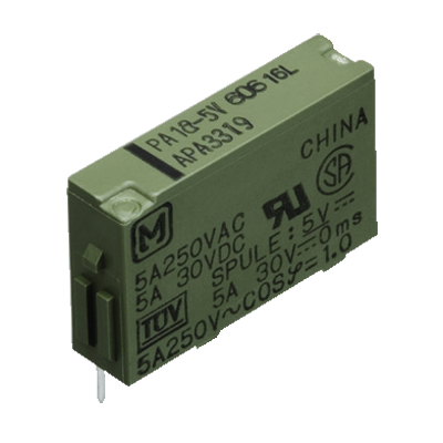
slim power relay
for interface
RoHS compliant
Protective construction: Sealed type
FEATURES
1. Slim size (width 5 mm .197 inch,
height 12.5 mm .492 inch) permits
higher density mounting
Despite the slim 5 mm .197 inch width,
the 20 mm .787 inch length is still
compact and the 12.5 mm profile is low.
Even when a socket is used, the height is
still only 18 mm .709 inch. Suitable for
high-density mounting, these relays
enable device size smaller.
2. Nominal operating power: High
sensitivity of 120mW
Enables smaller power supplies,
facilitates energy saving applications,
and contributes to device size smaller.
3. Control from low level loads to 5 A
Use of gold-clad twin contacts enables
control of low level loads down to 100 mV
100 µA and up to 5 A 250 V AC and 30 V
DC.
4. Reinforced according to IEC1131-2
(TÜV)
5. High surge breakdown voltage
(4000 V) and high breakdown voltage
(2000 V)
Between contacts and coil of 2,000 V and
surge resistance of 4,000 V work to
prevent controller malfunctions caused by
noise and surges.
6. Outstanding vibration and shock
resistance
Functional shock resistance: 147 m/s2
Functional vibration resistance:
10 to 55 Hz (at double amplitude of
2.5 mm .098 inch)
Keeps equipment from miss-operation
due to vibration and shock.
Can be used as mounted on control
panel doors.
PA RELAYS
7. Sealed construction allows
automatic washing
8. SIL (single in line) terminal layout
9. Complies with safety standards
Complies with Japanese Electrical
Appliance and Material Safety Law, and
certified by UL, CSA, and TÜV.
10. Sockets are available
TYPICAL APPLICATIONS
1. Industrial equipment, office
equipment
2. Measuring devices and test
equipment
3. Interface relays for programmable
controllers
4. Output relays in small devices such
as timers, counters, sensors, and
temperature controllers
ORDERING INFORMATION
PA 1a
Contact arrangement
1a: 1 Form A (Bifurcated)
Nominal coil voltage (DC)
5, 6, 9, 12, 18, 24V
Note: Certified by UL, CSA and TÜV
TYPES
Contact arrangement
1 Form A
Nominal coil voltage
5V DC
6V DC
9V DC
12V DC
18V DC
24V DC
Part No.
PA1a-5V
PA1a-6V
PA1a-9V
PA1a-12V
PA1a-18V
PA1a-24V
Standard packing: Tube: 25 pcs.; Case: 1,000 pcs.
* Terminal sockets available.
2014.02
industrial.panasonic.com/ac/e/
–1–
© Panasonic Corporation 2014
ASCTB204E 201402-T
�PA
RATING
1. Coil data
5V DC
Nominal operating
current
[±10%] (at 20°C 68°F)
24mA
6V DC
9V DC
12V DC
18V DC
24V DC
20mA
13.3mA
10mA
6.7mA
7.5mA
Nominal coil
voltage
Pick-up voltage
(at 20°C 68°F)
70%V or less of
nominal voltage *1
(Initial)
Drop-out voltage
(at 20°C 68°F)
5%V or more of
nominal voltage*1
(Initial)
Coil resistance
[±10%] (at 20°C 68°F)
Nominal operating
power
Max. applied voltage
(at 20°C 68°F)
120mW
120%V of
nominal voltage
208Ω
300Ω
675Ω
1,200Ω
2,700Ω
3,200Ω
180mW*2
Notes: *1 Pulse drive (JIS C 5442)
*2 24V DC, 120mW type are also available, please consult us.
2. Specifications
Characteristics
Contact
Rating
Electrical
characteristics
Item
Arrangement
Contact resistance (Initial)
Contact material
Nominal switching capacity (resistive load)
Max. switching power (resistive load)
Max. switching voltage
Max. switching current
Nominal operating power
Min. switching capacity (Reference value)*1
Insulation resistance (Initial)
Breakdown voltage
(Initial)
Between open contacts
Between contact and coil
1,000 Vrms for 1min. (Detection current: 10mA.)
2,000 Vrms for 1min. (Detection current: 10mA.)
Surge breakdown
voltage (Initial)
Between contacts and coil*2
4,000 V
Temperature rise (coil) (at 20°C 68°F)
Operate time (at nominal voltage) (at 20°C 68°F)
Release time (at nominal voltage) (at 20°C 68°F)
Functional
Destructive
Functional
Vibration resistance
Destructive
Mechanical
Shock resistance
Mechanical
characteristics
Expected life
Conditions
Specifications
1 Form A (Bifurcated)
Max. 30 mΩ (By voltage drop 6 V DC 1A)
Au-clad AgNi type
5 A 250 V AC, 5 A 30 V DC
1,250 VA, 150 W
250 V (AC), 110 V (DC)
5A
120 mW (5 to 18 V DC), 180 mW (24 V DC)
100µA 100mV DC
Min. 1,000MΩ (at 500V DC) Measurement at same location as “Breakdown voltage” section.
Electrical
Conditions for operation, transport and storage*3
Max. operating speed
Unit weight
Max. 45°C
(By resistive method, nominal coil voltage applied to the coil, nominal switching capacity.)
Max. 10 ms
Max. 5 ms
Min. 147 m/s2 (Half-wave pulse of sine wave: 11 ms; detection time: 10µs.)
Min. 980 m/s2 (Half-wave pulse of sine wave: 6 ms.)
10 to 55 Hz at double amplitude of 2.5 mm (Detection time: 10µs.)
10 to 55 Hz at double amplitude of 3.5 mm
Min. 2×10⁷ (at 180 times/min.)
Min. 105 (3 A 250 V AC, 30 V DC, resistive load)
Min. 5×10⁴ (5 A 250 V AC, 30 V DC, resistive load) (at 20 times/min.)
Ambient temperature: –40°C to 70°C –40°F to 158°F;
Humidity: 5 to 85% R.H. (Not freezing and condensing at low temperature)
20 times/min. (at nominal switching capacity)
Approx. 3 g .15 oz
Notes: *1. This value can change due to the switching frequency, environmental conditions, and desired reliability level, therefore it is recommended to check this with the
actual load.
*2. Wave is standard shock voltage of ±1.2×50µs according to JEC-212-1981
*3. The upper limit of the ambient temperature is the maximum temperature that can satisfy the coil temperature rise value. Refer to Usage, transport and storage
conditions in NOTES.
REFERENCE DATA
1. Max. switching capacity
2. Life curve
3.-(1) Coil temperature rise (180 mW)
Tested sample: PA1a-24V
Measured portion: Inside the coil
Ambient temperature: 20°C 68°F
1
DC resistive load
90
Temperature rise, °C
AC resistive load
5
4
3
2
No. of operations, ×104
Contact current, A
100
100
50
30
20
10
AC 125 V resistive load
DC 30 V resistive load
AC 250 V resistive load
0.5
0.4
0.3
0.2
80
70
60
50
5A
3A
2A
0A
40
30
20
10
20 30 50 100 200 300
Contact voltage, V
0.5
1
2 3 5 10
Switching capacity, A
Panasonic Corporation Automation Controls Business Division
industrial.panasonic.com/ac/e/
–2–
100
0
100
110 120 130 140 150
Coil applied voltage, %V
© Panasonic Corporation 2014
ASCTB204E 201402-T
�PA
3.-(2) Coil temperature rise (120 mW)
4.-(1) Operate & release time (120 mW)
4.-(2) Operate & release time (180 mW)
Tested sample: PA1a-12V
Measured portion: Inside the coil
Ambient temperature: 20°C 68°F
Tested sample: PA1a-12V, 20 pcs.
Tested sample: PA1a-24V, 20 pcs.
9
80
70
60
50
40
5A
3A
2A
0A
30
20
7
6
Operate time
5
Max.
x
Min.
4
3
Release time
Max.
x
Min.
2
10
0
8
1
100
0
110 120 130 140 150
Coil applied voltage, %V
80
6. Malfunctional shock
Tested sample: PA1a-12V, 6 pcs.
Tested sample: PA1a-12V, 6 pcs.
Rate of
change, %
40
30
20
X
Pick-up voltage
Z
Z’Y’
Y
7
6
Operate time
5
4
3
Max.
x
Min.
Max.
x
Min.
Release time
2
1
80
90
100 110 120
Coil applied voltage, %V
Deenergized
condition
Energized
condition
Y
980m/s2
X’
X
980m/s2
10
8
0
90
100 110 120
Coil applied voltage, %V
5. Ambient temperature characteristics
Operate & release time, ms
10
9
Operate & release time, ms
10
90
Temperature rise, °C
100
Z
980m/s2
Drop-out voltage
–40
–20
50
20
0
–10
–20
75
Ambient
temperature, °C
980m/s2
Z’
980m/s2
X’
–30
980m/s2
Y’
–40
DIMENSIONS (mm inch)
The CAD data of the products with a
CAD Data
mark can be downloaded from: http://industrial.panasonic.com/ac/e/
Relay
External dimensions
CAD Data
0.5
.020
1.3
.051
8.8
.346
PC board pattern (Bottom view)
1.2
.047 12.5
2.9 (12.8 max.)
.114 .492
(.504 max.)
6 4.8
.237 .189
2.54
.100
3.5
.138
5
.197
2.54
.100
1.2 dia.
.047 dia.
1.2 dia.
.047 dia.
1.0 dia.
.039 dia.
1.0 dia.
.039dia.
0.5
.020
10.16
.400
20
.787
5.08
.200
0.8
.031
1.11
.044
0.25
.010
1.18
.046
10.16
.400
5.08
.200
Tolerance: ±0.1 ±.004
Schematic (Bottom view)
1 2
General tolerance: ±0.3 ±.012
5
6
N.O. COM
Coil
SAFETY STANDARDS
UL/C-UL (Recognized)
File No.
Contact rating
E43149
5A 250V AC (5×10⁴)
5A 30V DC (5×10⁴)
3A 250V AC (105)
3A 30V DC (105)
File No.
LR26550
etc.
CSA (Certified)
Contact rating
5A 250V AC (5×10⁴)
5A 30V DC (5×10⁴)
3A 250V AC (105)
3A 30V DC (105)
File No.
B 12 01
13461 316
Panasonic Corporation Automation Controls Business Division
industrial.panasonic.com/ac/e/
–3–
TÜV (Certified)
Rating
IEC1131-2
Reinforced
Remarks
TÜV rating
5A 250V AC (cosφ =1.0) (5×10⁴)
5A 30V DC (0ms) (5×10⁴)
3A 250V AC (cosφ =1.0) (105)
3A 30V DC (0ms) (105)
© Panasonic Corporation 2014
ASCTB204E 201402-T
�PA
NOTES
4. When mounting the relays within
1 mm .039 inch, please notice the
condition below.
1) Mount the relays in the same direction.
4) About the electrical life for close
mounting, please refer to data below.
3.0
2.0
Within 1 mm
.039 inch
Contact current, A
1. For cautions for use, please read
“GENERAL APPLICATION
GUIDELINES” on page B-1.
2. If it includes ripple, the ripple factor
should be less than 5%.
3. Specification values for pick-up and
drop-out voltages are for the relay
mounting with its terminals below.
100
90
AC resistive load
DC resistive load
1.0
0.5
0.4
0.3
80
60
Max.
–
x
Min.
50
40
0.2
2) Coil terminals (Terminal No. 1 & 2)
polarity should be arranged in the same
direction.
20
30
50
100
Contact voltage, V
200 300
30
20
Drop-out voltage
10
Max.
–
x
Min.
0
Mounting
direction
–.
+.
–.
+.
–.
+.
–.
+.
–.
+.
+.
–.
+.
–.
+.
–.
+.
–.
3) Allowable contact current is 2 A.
+.
–.
No. of operations, ×104
Voltage, %V
70
Pick-up voltage
100
50
40
30
20
AC 125V
resistive load
DC 30 V
resistive load
AC 250 V
resistive load
10
0.5
Panasonic Corporation Automation Controls Business Division
industrial.panasonic.com/ac/e/
–4–
© Panasonic Corporation 2014
1.0
2.0
3.0
Switching capacity, A
ASCTB204E 201402-T
�Automation Controls Catalog
PA RELAYS
TERMINAL SOCKETS
ACCESSORIES
TYPES
Product name
Standard type terminal socket
Self clinching type terminal socket
Standard type
terminal socket
Self clinching type
terminal socket
DIMENSIONS (mm inch)
The CAD data of the products with a
Standard type terminal socket
External dimensions
CAD Data
1
2
3
4
5
CAD Data
mark can be downloaded from: http://industrial.panasonic.com/ac/e/
Self clinching type terminal socket
External dimensions
CAD Data
5+0.2
–0.6
.197+.008
–.024
6
1
22.6±0.6
.890±.024
4
.157
Part No.
PA1a-PS
PA1a-PS-H
0.5
.020
2.54
.100
6.35
.250
2
3
4
5
5+0.2
–0.6
.197+.008
–.024
6
22.6±0.6
.890±.024
0.8
.031
3.81
.150
9±0.6
.354±.024
9±0.6
.354±.024
5.3±0.6
.209±.024
5.3±0.6
.209±.024
(0.3)
(.012)
5.08
.200
3.9
1±0.25
.154
.039±.010
1.23
.048
0.25
.010
1.23
.048
0.8
.031
0.5
.020
2.54
.100
6.35
.250
3.81
.150
(0.3)
(.012)
5.08
.200
General tolerance: ±0.3 ±.012
General tolerance: ±0.3 ±.012
PC board pattern (Bottom view)
PC board pattern (Bottom view)
1.0 dia.
.039 dia.
1.0 dia.
.039 dia.
2.54
.100
10.16
.400
1.2 dia.
.047 dia.
1.2 dia.
.047 dia.
1.3±0.15
.051±.006
0.8±0.25 dia. 1.2±0.05 dia.
.031±.010 dia. .047±.002 dia.
0.8±0.25 dia.
1.2±0.05 dia.
.031±.010 dia. .047±.002 dia.
5.08
.200
2.54
.100
Tolerance: ±0.1 ±.004
10.16
.400
5.08
.200
Tolerance: ±0.1 ±.004
INSTALLING AND REMOVING
Installing and removing the relay
1) Firmly insert the relay into the socket
with the terminals going in the direction of
the blade receptacles.
(1) Insert the removal key into the socket
slots.
2014.02
2) The relay can be easily removed using
the removal key (APA801).
(2) Pull the removal key up to remove the
relay.
industrial.panasonic.com/ac/e/
–1–
(3) Slide the removal key off of the relay.
© Panasonic Corporation 2014
ASCTB263E 201402-T
�


 工商网监
湘ICP备2023018690号
工商网监
湘ICP备2023018690号

