PHOTOELECTRIC SENSORS
PX-2 SERIES
CY
Long Range & Wide Area Photoelectric Sensor
Amplifier Built-in
Conforming to
EMC Directive
Ideal sensing area with very little null zone
Compact size for space-saving
The advanced optical system of the PX-2 series reduces the null zones in front of
an automatic guided vehicle (AGV).
The null zones at the sides are further minimized if auxiliary sensors which can be
easily mounted with connectors are used.
(For PX-24, PX-24ES, PX-23ES and PX-26)
Its size is half of a conventional model,
and the attached cable orientation is
freely adjustable. Hence, it can also fit
in a small AGV.
Moreover, sensitivity adjustment can
be done on the front face.
Auxiliary sensor
(Optional)
Auxiliary left OUT 1 area (700 mm 27.559 in)
PM2
Micro
PM
MS-AJ
Sensor Mounting Stand
RT-610
PX-2
Amplifier Built-in
Compact size sensor
realizes wide sensing
area & long sensing
range
Adjacent left OUT 1 area
OUT 1 area: 3 m 9.843 ft
1 m 3.281 ft with PX-21
and PX-23ES,
5 m 16.404 ft with PX-26
)
OUT 2 area: 3 m 9.843 ft
1 m 3.281 ft with PX-21
and PX-23ES,
5 m 16.404 ft with PX-26
(
)
83 mm
3.268 in
43 mm
1.693 in
Adjacent right OUT 1 area
Auxiliary sensor
(Optional)
Auxiliary right OUT 1 area (700 mm 27.559 in)
Sensitivity adjuster
Sensing areas selectable as per route condition
Long sensing range 5 m 16.404 ft type
Sensing areas can be selected with switches to suit the route conditions of an
AGV.
Further, in case of PX-24ES and PX-23ES, the sensing areas can also be
selected with external signals.
PX-26 has a long sensing range of 5 m
16.404 ft. Even on a high-speed AGV,
it can detect an object quite early so
that slowing down and stopping are
smooth.
EQ-500
VF
Multi-voltage
NX5
(
62 mm
2.441 in
314
Ramco Innovations - 1207 Maple Street, West Des Moines IA USA 50265 - 800-280-6933 - www.ramcoinnovations.com
�PHOTOELECTRIC SENSORS
PX-2
ORDER GUIDE
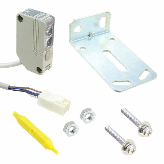
Accessories
Appearance
Sensing range
Model No.
• MS-PX-2 (Main sensor mounting bracket)
Two bracket set
Four M4 (length 8 mm
0.315 in) screws with
washers are attached.
PX-22
1 m 3.281 ft
PX-21
PX-24
Amplifier Built-in
RT-610
PX-2
Short
sensing
range
CY
3 m 9.843 ft
• MS-NX5-1 (Auxiliary sensor mounting bracket)
With
external
control
function
3 m 9.843 ft
Two M4 (length 25 mm
0.984 in) screws with
washers and two M4 nuts
are attached.
PX-24ES
1 m 3.281 ft
PX-23ES
5m
16.404 ft
Auxiliary
sensor
700 mm 27.559 in
PX-26
PX-SB1
Sensor Mounting Stand
MS-AJ
Long
sensing Short
sensing
range
range
Auxiliary sensor connectable type
Standard type
Type
OPTIONS
Auxiliary sensor mounting bracket
Back angled mounting bracket
PM
MS-NX5-3
Two M4 (length 25 mm
0.984 in) screws with
washers and two M4 nuts
are attached.
PM2
Foot biangled mounting bracket (Sensor protection bracket)
• MS-NX5-3
Two M4 (length 25 mm
0.984 in) screws with
washers and two M4 nuts
are attached.
Sleep function
Automatic interference prevention function
External sensitivity adjustment
The sensor can be put into the sleep
(stand-by) condition when it is not
used and can be restored to operating
condition by an external signal.
Consequently battery is conserved as
the power consumption is reduced to
1/7.
One PX-2 sensor can simultaneously
receive beams from 25 Nos. of other
PX-2 sensors without resulting in any
interference. Even if AGVs are facing
each other, the PX-2 sensor on one
AGV reliably detects the other AGVs.
Hence, it can be safely used even at a
place where several AGVs are moving.
The sensitivity of the sensor can be
adjusted, within the range set by the
manual adjuster, by an external input.
For PX-24, PX-24ES, PX-23ES and
PX-26
(
)
Sleep condition
�
�
A.G.V.
Sleep input ON
The sensitivity can be decreased
at a corner of the path so as not
to detect the wall.
Wake-up condition
�
�
A.G.V.
26 Nos. of PX-2’s can work at one site.
Sleep input OFF
Ramco Innovations - 1207 Maple Street, West Des Moines IA USA 50265 - 800-280-6933 - www.ramcoinnovations.com
315
NX5
MS-NX5-2
• MS-NX5-2
EQ-500
Description
Micro
Auxiliary sensor
mounting bracket
Model No.
Multi-voltage
VF
Designation
�PHOTOELECTRIC SENSORS
PX-2
SPECIFICATIONS
Main sensors
Type
Auxiliary sensor connectable model
Standard model
With external control function
Short sensing range
CY
Item
Model No.
RT-610
PX-2
Amplifier Built-in
Sensing range (OUT 1 and OUT 2 areas) (Note 1)
PX-22
PX-21
3 m 9.843 ft
1 m 3.281 ft
PX-24
PX-24ES
3 m 9.843 ft
Long sensing range
PX-23ES
PX-26
1 m 3.281 ft
5 m 16.404 ft
15 % or less of operation distance
Hysteresis
10 to 31 V DC including ripple
Supply voltage
Under operation: 1.5 W or less, Under sleep condition: 0.3 W or less (without auxiliary sensor)
Power consumption (Note 2)
OUT 1
OR circuit among the effective center, left,
right, adjacent left / right OUT 1 areas
and the effective auxiliary left / right areas
OUT 2
OR circuit among the effective
center, left and right OUT 2 areas
(
)
(
)
NPN open-collector transistor
• Maximum sink current: 100 mA
• Applied voltage: 40 V DC or less (between OUT 1 / OUT 2 and 0 V)
• Residual voltage: 1.5 V or less (at 100 mA sink current)
0.4 V or less (at 16 mA sink current)
DC-12 or DC-13
Utilization category
Output operation
Selectable either Light-ON or Dark-ON with a switch (Output operation of OUT 1 and OUT 2 is the same.)
Incorporated
Short-circuit protection
MS-AJ
Sensor Mounting Stand
Short sensing range
NPN open-collector transistor
• Maximum sink current: 100 mA
• Applied voltage: 40 V DC or less (between extraneous light monitor output and 0 V)
• Residual voltage: 1.5 V or less (at 100 mA sink current)
0.4 V or less (at 16 mA sink current)
Extraneous light monitor output
ON when modulated beam other than its own (including auxiliary sensor’s) light is received
Output operation
Short-circuit protection
80 ms or less
PM
Response time
PM2
Micro
Operation
indicators
OUT 1 area
OUT 2 area
Red LED (lights up when the beam is received in the effective OUT 1 areas)
Yellow LED (lights up when the beam is received in the effective OUT 2 areas)
Continuously variable adjusters (OUT 1, adjacent right OUT 1, adjacent left OUT 1 and OUT 2 areas are adjusted independently.)
Sensitivity adjuster
Sensitivity adjustment is possible with an analog input.
External sensitivity adjustment function
Optical interference from up to 25 units is prevented.
3 (Industrial environment)
IP65 (IEC)
Protection
Environmental resistance
NX5
Pollution degree
VF
Multi-voltage
Fixed
Operating / sleep selectable with external input
Sleep function
Automatic interference prevention function
Ambient temperature
�10 to�55 �C �14 to�131 �F (No dew condensation or icing allowed), Storage:�20 to�70 �C �4 to�158 �F
35 to 85 % RH, Storage: 35 to 85 % RH
Ambient humidity
Ambient illuminance
Sunlight: 9,000 ?x at the light-receiving face, Incandescent light: 3,000 ?x at the light-receiving face
EN 50081-2, EN 50082-2, EN 60947-5-2
EMC
Voltage withstandability
1,000 V AC for one min. between all supply terminals connected together and enclosure
Insulation resistance
20 MΩ, or more, with 500 V DC megger between all supply terminals connected together and enclosure
Vibration resistance
10 to 500 Hz frequency, 3 mm 0.118 in amplitude (20 G max.) in X, Y and Z directions for two hours each
Shock resistance
EQ-500
Four sensing areas are selectable with dip switches, and
eight sensing areas are selectable with external inputs.
Four sensing areas are selectable with dip switches.
Sensing area
500 m/s2 acceleration (50 G approx.) in X, Y and Z directions for three times each
Infrared LED (modulated)
Emitting element
Enclosure: ABS, Lens: Acrylic, Cover: Polycarbonate
Material
Cable
Cable extension
Weight
Accessories
0.3 mm2 5-core cabtyre cable, 0.5 m
1.640 ft long (for input and output)
For input and output: 0.18 mm2 9-core (PX-24ES and PX-23ES: 12-core) cabtyre cable, 0.5 m 1.640 ft long
For auxiliary sensor connection: 0.18 mm2 10-core connector attached cabtyre cable, 0.5 m 1.640 ft long
Extension up to total 100 m 328.084 ft (10 m 32.808 ft for auxiliary sensor connection) is possible with 0.3 mm2, or more, cable.
170 g approx.
210 g approx.
220 g approx.
210 g approx.
MS-PX-2 (Main sensor mounting bracket): 1 set, Adjusting screwdriver: 1 pc., Matrix chart for sensing areas and external inputs: 1 sheet (PX-24ES and PX-23ES only)
Notes: 1) The sensing range is specified for white non-glossy paper (300�300 mm 11.811�11.811 in).
Notes: 2) Obtain the current consumption by the following calculation.
Notes: 2) Current consumption�Power consumption�Supply voltage
(e.g.) When the supply voltage is 12 V, the current consumption (operating condition) is: 1.5 W�12 V�0.125 A�125 mA
316
Ramco Innovations - 1207 Maple Street, West Des Moines IA USA 50265 - 800-280-6933 - www.ramcoinnovations.com
�PHOTOELECTRIC SENSORS
PX-2
SPECIFICATIONS
Auxiliary sensor (Note 1)
Model No.
PX-SB1
PX-24, PX-24ES, PX-23ES or PX-26
Applicable main sensor
Up to two PX-SB1’s can be connected to one main sensor.
Connectable units
700 mm 27.559 in
Sensing range (Note 2)
CY
Item
Supplied from the main sensor
Supply voltage
Amplifier Built-in
RT-610
PX-2
Current consumption of the main sensor increases by 30 mA approx. per auxiliary sensor.
Current consumption
OR circuit with the main sensor’s OUT 1
Output
Operation indicator
Red LED (lights up when the beam is received)
Sensitivity adjuster
Continuously variable adjuster
Infrared LED (modulated)
Emitting element
Polycarbonate
Material
0.3 mm2 5-core cabtyre cable, 2 m 6.562 ft long
Cable
Extension up to total 10 m 32.808 ft is possible with 0.3 mm2, or more, cable.
Cable extension
Weight
130 g approx.
Accessories
Sensor Mounting Stand
MS-AJ
MS-NX5-1 (Auxiliary sensor mounting bracket): 1 set, Adjusting screwdriver: 1 pc.
Specifications other than the above are identical with the main sensor.
Notes: 1) The auxiliary sensor cannot be used as a stand-alone unit.
Notes: 2) The sensing range is specified for white non-glossy paper (300�300 mm 11.811�11.811 in) as the object.
I/O CIRCUIT AND WIRING DIAGRAMS
Wiring diagram
Color code
For auxiliary
sensor connection
(Brown)�V
ZD2
Tr3
Load
100 mA max.
(White) OUT 2
Load �
100 mA max.
(Black / White) Extraneous light monitor output
�
Blue
Sensor circuit
m1
(Blue) 0 V
(Pink)
Area Selection Input 1
Pink
m1
Pink / Black
(Pink / Black)
Area Selection Input 2
Internal circuit
10 to 31 V DC
Black / White
10 to 31 V DC
100 mA max.
ZD3
�
�
PM2
White
Load
(Pink / White)
Area Selection Input 3
Pink / White
(Violet) Auxiliary right OUT 1
area ineffective input
Violet
(Violet / Black) Auxiliary left
OUT 1 area ineffective input
Violet / Black
(Pink / Violet) Sleep input
Pink / Violet
(Pink / Gray) External 6 mA max.
sensitivity adjustment input
(Input impedance: 1 k٠approx.) ��
0 to �5 V DC
Users’ circuit
NX5
ZD1
Tr2
Load
Pink / Gray
��
0 to �5 V DC
m1
EQ-500
Load
(Black) OUT 1
Tr1
Load
Black
Multi-voltage
VF
D
Brown
Micro
I/O circuit diagram
PM
PX-24ES
PX-23ES
Non-voltage contact or NPN open-collector transistor
Symbols ... D: Reverse supply polarity protection diode
ZD1, ZD2, ZD3: Surge absorption zener diode
Tr1, Tr2, Tr3 : NPN output transistor
or
• Area selection input
Low (0 to 1 V): Depends on the logic combination (refer to p.322)
High (4.5 to 31 V, or open): Depends on the logic combination (refer to p.322)
• Auxiliary area ineffective input
Low (0 to 1 V): Area ineffective
High (4.5 to 31 V, or open): Area effective
• Sleep input
Low (0 to 1 V): Sleep condition
High [(supply voltage�1 V) to 31 V, or open]: Operating condition
Ramco Innovations - 1207 Maple Street, West Des Moines IA USA 50265 - 800-280-6933 - www.ramcoinnovations.com
317
�PHOTOELECTRIC SENSORS
PX-2
I/O CIRCUIT AND WIRING DIAGRAMS
PX-22
PX-21
I/O circuit diagram
Wiring diagram
Color code
(Brown)�V
CY
D
(Black) OUT1
RT-610
Sensor circuit
PX-2
Amplifier Built-in
Tr 1
Brown
Load
�
�
Load
100 mA max.
(White) OUT2
Z D1
Tr 2
Load
Black
�
�
White
100 mA max.
Z D2
(Blue) 0 V
10 to 31 V DC
Blue
m1
m1
(Pink / Violet) Sleep input
Pink / Violet
Internal circuit
Users’ circuit
m1
Non-voltage contact or NPN open-collector transistor
Symbols ... D: Reverse supply polarity protection diode
ZD1, ZD2: Surge absorption zener diode
Tr1, Tr2 : NPN output transistor
MS-AJ
Sensor Mounting Stand
or
• Low (0 to 1 V): Sleep condition
• High [(supply voltage�1 V) to 31 V, or open]: Operating condition
PM
PX-24
PX-26
I/O circuit diagram
For auxiliary
sensor connection
Micro
(Brown)�V
D
(Black) OUT 1
Tr1
PM2
ZD1
Tr2
Sensor circuit
NX5
VF
Multi-voltage
Wiring diagram
Color code
ZD2
EQ-500
Load
10 to 31 V DC
Tr3
Brown
Load
Load
Load
100 mA max.
(White) OUT 2
Black
Load
100 mA max.
(Black / White) Extraneous light monitor output
�
�
Load
10 to 31 V DC
White
�
�
10 to 31 V DC
Black / White
100 mA max.
ZD3
Load
(Blue) 0 V
m1
(Violet) Auxiliary right
OUT 1 area ineffective input
Blue
(Violet / Black) Auxiliary left
OUT 1 area ineffective input
Violet
m1
Internal circuit
Violet / Black
(Pink / Violet) Sleep input
(Pink / Gray)
External sensitivity
6 mA max.
adjustment input
(Input impedance: 1 k٠approx.) ��
0 to�5 V DC
Users’ circuit
Pink / Violet
Pink / Gray
��
0 to�5 V DC
m1
Symbols ... D: Reverse supply polarity protection diode
ZD1, ZD2, ZD3: Surge absorption zener diode
Tr1, Tr2, Tr3 : NPN output transistor
Non-voltage contact or NPN open-collector transistor
or
• Auxiliary area ineffective input
Low (0 to 1 V): Area ineffective
High (4.5 to 31 V, or open): Area effective
• Sleep input
Low (0 to 1 V): Sleep condition
High [(supply voltage�1 V) to 31 V, or open]: Operating condition
318
Ramco Innovations - 1207 Maple Street, West Des Moines IA USA 50265 - 800-280-6933 - www.ramcoinnovations.com
�PHOTOELECTRIC SENSORS
PX-2
SENSING CHARACTERISTICS (TYPICAL)
How to read sensing characteristics
L
#
L’
L:
C:
R:
L’ :
R’ :
L
300�300 mm
11.811�11.811 in
White non-glossy paper
L
C
Left area
Center area
Right area
R’
Adjacent left OUT 1 area
Adjacent right OUT 1 area
R
L
It shows the variation in the
sensing range when the
external input voltage is
changed from 0 to � 5 V
with the sensitivity adjuster
set at the maximum sensing
range.
Sensing object
Horizontal
(left-right) direction
Type of non-glossy paper
Vertical (up-down) direction
Note: The sensitivity has been adjusted so that the
maximum sensing range for white non-glossy paper
(300�300 mm 11.811�11.811 in) is 3 m 9.843 ft
(1 m 3.281 ft for PX-21 and PX-23ES, 5 m 16.404 ft
for PX-26) with the L, C and R areas effective.
White non-glossy paper (lightness: 9)
Gray non-glossy paper (lightness: 5)
Black non-glossy paper (lightness: 2)
All models
Correlation between setting distance and excess gain
100
Sensor Mounting Stand
MS-AJ
PX-26
10
PX-22 PX-24
PX-24ES
5
PX-SB1
Sensing fields
• All areas effective (Horizontal)
Black nonglossy paper
2
6.562
1
3.281
0
1
3.281
4
13.123
3
9.843
3
9.843
Max. sensing range: 3 m 9.843 ft
3
9.843
2
6.562
1
3.281
0
1
3.281
0.5
0
0.5
1
1.640
1.640
3.281
Center
Left
Right
Operating point ?(m ft)
White nonglossy paper
Gray nonglossy paper
White nonglossy paper
2
6.562
Gray nonglossy paper
1
3.281
0
1
3.281
0.5
0
0.5
1
1.640
1.640
3.281
Center
Left
Right
Operating point ?(m ft)
0.5
0
0.5
1.640
1.640
Center
Down
Up
Operating point ?(m ft)
0
400
15.748
200
0
200
400
7.874
7.874 15.748
Left
Center
Right
Operating point ?(mm in)
0.5
1.640
0
400
15.748
200
0
200
400
7.874
7.874 15.748
Left
Center
Right
Operating point ?(mm in)
1 White non3.281 glossy paper
Gray nonglossy paper
0.5
1.640
0
400
15.748
200
0
200
7.874
7.874
Down
Center
Up
Operating point ?(mm in)
Sensing range L (m ft)
0.5
1.640
1
3.281 White nonglossy paper
Gray nonglossy paper
1
2
3
4
External sensitivity adjustment
input voltage (V)
5
Correlation between external sensitivity
adjustment input voltage and sensing range
(PX-23ES only)
• All areas effective (Vertical)
Setting distance L (m ft)
Black nonglossy paper
Setting distance L (m ft)
Setting distance L (m ft)
White non1 glossy paper
3.281
Gray nonglossy paper
• C area effective (Horizontal)
Max. sensing range: 1 m 3.281 ft
1
3.281
0
1
3.281
PX-21
PX-23ES
Sensing fields
• All areas effective (Horizontal)
Max. sensing range: 2 m 6.562 ft
2
6.562
400
15.748
1
3.281
0.5
1.640
0
Max. sensing range: 1 m 3.281 ft
Max. sensing range: 0.5 m 1.640 ft
1
2
3
4
External sensitivity adjustment
input voltage (V)
Ramco Innovations - 1207 Maple Street, West Des Moines IA USA 50265 - 800-280-6933 - www.ramcoinnovations.com
NX5
3
9.843
4
13.123
Sensing range L (m ft)
White nonglossy paper
• All areas effective (Vertical)
4
13.123
Setting distance L (m ft)
Gray nonglossy paper
• C area effective (Horizontal)
Setting distance L (m ft)
Setting distance L (m ft)
4
13.123
Correlation between external sensitivity
adjustment input voltage and sensing range
(Excluding PX-22)
PM2
PX-22 PX-24
PX-24ES
EQ-500
0
PM
PX-21
PX-23ES
1
2
3
4
5
3.281 6.562 9.843 13.123 16.404
Setting distance L (m ft)
Micro
1
Multi-voltage
VF
Excess gain
50
CY
#
• Correlation between external sensitivity
adjustment input voltage and sensing range
Sensing area
300�300 mm
11.811�11.811 in
Non-glossy paper
Amplifier Built-in
RT-610
PX-2
• Sensing field
5
319
�PHOTOELECTRIC SENSORS
PX-2
SENSING CHARACTERISTICS (TYPICAL)
PX-26
Sensing fields
• Horizontal (Area selection not possible)
• Vertical (Area selection not possible)
CY
8
26.247
Correlation between external sensitivity
adjustment input voltage and sensing range
8
26.247
8
26.247
6
19.685
6
19.685
Black nonglossy paper
2
6.562
0
1
3.281
0.5
0
0.5
1
1.640
1.640
3.281
Center
Left
Right
Operating point ?(m ft)
White nonglossy paper
4
13.123
Gray nonglossy paper
2
6.562
0
1
3.281
0.5
0
0.5
1.640
1.640
Center
Down
Up
Operating point ?(m ft)
1
3.281
Sensing range L (m ft)
Gray nonglossy paper
Setting distance L (m ft)
Setting distance L (m ft)
White nonglossy paper
4
13.123
RT-610
PX-2
Amplifier Built-in
Max. sensing range: 4 m 13.123 ft
6
19.685
Max. sensing range:
5 m 16.404 ft
Max. sensing range:
4 3 m 9.843 ft
13.123
2
6.562
0
Max. sensing range: 2 m 6.562 ft
Max. sensing range: 1 m 3.281 ft
1
2
3
4
External sensitivity adjustment
input voltage (V)
5
PM2
Micro
Sensing field
• Horizontal and vertical directions
0.8
2.625
Setting distance L (m ft)
PM
MS-AJ
Sensor Mounting Stand
PX-SB1
0.6
1.969
White nonglossy paper
0.4
1.312
0.2
0.656
0
40
20
0
20
40
1.575
0.787
0.787
1.575
Center
(Down) Left
Right (Up)
Operating point ?(mm in)
PRECAUTIONS FOR PROPER USE
Refer to p.1135l for general precautions.
All models
EQ-500
VF
Multi-voltage
NX5
This product is not a safety sensor. Its use is not
intended or designed to protect life and prevent body
injury or property damage from dangerous parts of
machinery. It is a normal object detection sensor.
Hazard Indications
In this catalog, .......................
CAUTION are indicaWARNING and ......................
ted depending upon the level of danger. Please observe
them strictly for the safe use of this sensor.
WARNING
‘WARNING’ indicates a potentially hazardous situation that,
if not avoided, could result in death or serious injury.
CAUTION
‘CAUTION’ indicates a hazardous situation that, if not
avoided, may result in minor or moderate injury.
Further, they also indicate the condition of risk of physical
damage to machinery.
WARNING
• Installation of a touch bumper
• You are requested to always install a touch bumper when
this product is used on an automatic guided vehicle
(AGV).
320
CAUTION
• Use outside Japan
• This sensor conforms to the EMC Directive. However, it is
not certified by a competent body in accordance with other
country safety standards. Since each country has its
regulations, please follow the local and national
regulations of the country where this sensor is used.
CAUTION
• Fail-safe measures
• This sensor is meant for proximity detection and does not
possess control functions for safety maintenance.
• If fail-safe measures are required, consider their
incorporation in the total system.
• Further, do not connect the sensor output directly to a
stopping mechanism (brake).
CAUTION
• Periodical maintenance check
• The person incharge must periodically confirm the
performance of the product and maintain a record of such
checks. In addition, whenever the operating environment
of the product is changed due to system modification, etc.,
performance check must be done.
Ramco Innovations - 1207 Maple Street, West Des Moines IA USA 50265 - 800-280-6933 - www.ramcoinnovations.com
�PRECAUTIONS FOR PROPER USE
PHOTOELECTRIC SENSORS
PX-2
Refer to p.1135l for general precautions.
All models
7
5
3
1
CY
8
0
6
4
2
1
2
5
6
7
8
Sensing area selection
switch (Note 1)
Sensor mounting
bracket
MS-NX5-1
(Accessory)
Sensitivity
adjuster
4
OUT 2 area Lights up when light is received in OUT 2 area.
(Yellow LED)
OUT 1 area Lights up when light is received in OUT 1 area.
(Red LED)
OUT 2 area Sensitivity of the respective area is adjusted independently.
3
M4 (length 25 mm
0.984 in)
screw with washers
M4 nuts
Function
Adjacent left OUT 1 area
OUT 1 area
OUT 1 area
Adjacent right
OUT 1 area
Adjacent left
OUT 1 area
OUT 2 area
Adjacent right OUT 1 area
Left / right area is selected. (OUT 1 and OUT 2)
Left area
Left area
R L
Effective
Center area
OFF
R L
Right area
Ineffective
Right area
OFF
D.ON
Light-ON
D.ON
Dark-ON
L.ON
300 mm 11.811 in or more
Step Sensitivity adjuster
Total of 26 sensors
can be used at the
same place.
Operation
Make sure that the output operation mode selection
switch is set to L-ON (ON when receiving light), and
then turn the sensitivity adjuster fully counterclockwise.
A
Notes: 1) Response time of the sleep input is 50 ms.
Notes: 2) Reactivation from the sleep state to the operation state takes
0.7 sec. approx.
Notes: 2) Operation during this transient state should be avoided.
Notes: 3) When the sleep function is not used, keep the sleep input line open
or insulated and prevent contact with other wires.
External inputs
EXT.
Sensitivity adjustment
Place an object to be detected at the required sensing
position, and turn the sensitivity adjuster gradually clockwise
and mark the point @ where the indicator (Note 1) turns on.
2
Sleep (stand-by) function
• When the sleep input is made Low, the sensor goes into
the sleep state and the operation can be stopped.
INT.
Notes: 1) PX-26 does not incorporate it.
Notes: 2) PX-24ES and PX-23ES incorporate it.
1
Simultaneously
incident beam from
up to 25 sensors
DIP switch
EXT.
NX5
Automatic interference prevention function
• In case several sensors are used at the same place, take
care that the number of sensors from which beams may be
simultaneously incident is 25 or less.
INT.
PM2
External control
0 switch (Note 2)
This switch designates
whether the sensing area
selection is made by the
DIP switches or the
external inputs.
Micro
L.ON
3
Remove the object and turn the sensitivity adjuster
further clockwise. Find out the point b where the
indicator turns on again. Make sure that the difference
between point @ and b is 1 div., or more, on the
scale. Then, set the sensitivity adjuster at point @.
4
Carry out steps 1, 2 and 3 for each of the areas
OUT 2, OUT 1, adjacent left / right OUT 1 and
auxiliary sensors (if they are connected).
5
After all the adjustments are made, the operator must confirm
that the sensing area is set correctly by observing the detection
of the object as it approaches from different directions.
A
B
Notes: 1) When adjusting the sensitivity of OUT 1 area, adjacent right OUT 1 area and
adjacent left OUT 1 area, this is the OUT 1 area operation indicator (red).
When adjusting the sensitivity of OUT 2 area, this is the OUT 2
area operation indicator (yellow).
Notes: 2) Set areas other than the area you are adjusting as ineffective.
Notes: 3) Use the accessory screwdriver to slowly turn the sensitivity
adjuster. Turning with excessive force will damage the adjuster.
Ramco Innovations - 1207 Maple Street, West Des Moines IA USA 50265 - 800-280-6933 - www.ramcoinnovations.com
321
Multi-voltage
VF
• Mount the sensor, horizontally, at least 300 mm 11.811 in
above the floor, to avoid reflection from the floor.
Output operation mode of
Output operation
OUT 1 and OUT 2 is
9 mode switch
selected.
EQ-500
• The tightening torque for PX-SB1 (auxiliary sensor) should
be 0.8 N m or less.
Operation
indicator
Description
PM
Sensor
mounting
bracket
MS-PX-2
(Accessory)
9
Amplifier Built-in
RT-610
PX-2
M4 (length 8 mm
0.315 in)
screw with
washers
Functional description
Sensor Mounting Stand
MS-AJ
Mounting
• The tightening torque for the main sensor should be 1.2 N m or less.
�PRECAUTIONS FOR PROPER USE
Refer to p.1135l for general precautions.
PX-24 PX-24ES
PX-23ES PX-26
CY
PX-2
Amplifier Built-in
Others
• Do not use during the initial transient time (0.7 sec.) after
the power supply is switched on.
• Take care that an initial rush current (1.5 A approx. at 10 V
DC and 5 A approx. at 31 V DC) will flow when the power
supply is switched on.
PX-22 PX-21 PX-24
PX-24ES PX-23ES
RT-610
Notes: 1) The sensitivity of the auxiliary sensor is not changed.
Notes: 2) Sensitivity adjustment beyond the range set by the manual
sensitivity adjuster is not possible.
Input voltage
Sensing area selection
0V
Minimum
Setting method Internal setting Area selection inputs (Note) INT.
PX-24ES and
INT.
PX-23ES only EXT.
EXT.
Input 1 Input 2 Input 3
(
Sensing area
)
All areas ineffective
L
L
L
H
L
L
L
H
L
Center area effective
n �5 V or open
n Maximum
Sensitivity
sensitivity set by the
( Maximum
)
manual sensitivity adjuster
Note: This wire should be insulated if it is not used.
Extraneous light monitor function
(Incorporated in PX-24, PX-24ES, PX-23ES and PX-26 only)
• If the sensor receives modulated light other than its own
(including auxiliary sensor’s) light, the extraneous light
monitor output turns ON. The operation of the extraneous
light monitor output has absolutely no affect on sensing. It
is useful for recognizing presence of other sensors near
this sensor in case of intersecting AGV paths, etc.
Center, right and adjacent right OUT 1 areas
effective
PM2
Micro
PM
MS-AJ
Sensor Mounting Stand
External sensitivity adjustment function
• The sensitivity can be adjusted, within the range set by the
manual sensitivity adjuster, by an analog voltage (0 to �5 V)
applied to the external sensitivity adjustment input. The
sensitivity varies with the magnitude of the applied voltage.
n
All models
n
PHOTOELECTRIC SENSORS
PX-2
Center, left and adjacent left OUT 1 areas
effective
Center and adjacent left / right OUT 1 areas
effective
H
H
L
L
L
H
H
L
H
L
H
H
H
H
H
Note: The extraneous light monitor output is not incorporated with a shortcircuit protection circuit. Do not connect it directly to a power supply
or a capacitive load.
R L
NX5
OFF
Center, right and adjacent left / right OUT 1 areas
effective
R L
EQ-500
VF
Multi-voltage
OFF
Center, left and adjacent left / right OUT 1 areas
effective
R L
OFF
All areas effective
R L
OFF
L: Low (0 to 1 V), H: High (4.5 to 31 V, or open)
Note: The response time of the area selection inputs is 80 ms.
322
Ramco Innovations - 1207 Maple Street, West Des Moines IA USA 50265 - 800-280-6933 - www.ramcoinnovations.com
�PRECAUTIONS FOR PROPER USE
PHOTOELECTRIC SENSORS
PX-2
Refer to p.1135l for general precautions.
PX-SB1
CY
• This sensor must always be used with the applicable
main sensor. This sensor does not work as a standalone unit. (It cannot be used with PX-22 or PX-21.)
Sensing area
Amplifier Built-in
RT-610
PX-2
Selection of the auxiliary sensing areas
• The auxiliary sensing areas are controlled by the auxiliary
area ineffective inputs of the main sensor.
Area ineffective input Auxiliary left Auxiliary right
OUT 1 area OUT 1 area
Auxiliary left / right OUT 1 areas ineffective
L
L
H
L
L
H
H
H
Sensor Mounting Stand
MS-AJ
Auxiliary left OUT 1 area effective
PM
Auxiliary right OUT 1 area effective
PM2
Micro
Auxiliary left / right OUT 1 areas effective
EQ-500
Multi-voltage
VF
NX5
L: Low (0 to 1 V), H: High (4.5 to 31 V, or open)
Note: The ineffective auxiliary area inputs are not related to the external
control switch on the main sensor.
Ramco Innovations - 1207 Maple Street, West Des Moines IA USA 50265 - 800-280-6933 - www.ramcoinnovations.com
323
�PHOTOELECTRIC SENSORS
PX-2
PRECAUTIONS FOR PROPER USE
Refer to p.1135l for general precautions.
PX-SB1
Sensitivity adjustment
CY
Step
Emission
adjuster
Supplementary sensing adjustment with sensitivity adjuster
Operation
Remove the front cap.
• If the sensor receives beam emitted from the main sensor,
you will not be able to adjust the sensing range at shorter
distance. In such case, follow the below procedures to
modify the sensitivity.
Front cap
Turn the emission adjuster counterclockwise fully.
2
A
3
Receiving adjuster
4
A
Seal
Light receiving
indicator lights on.
8
object
Emission adjuster
Move the object out and find out the
point b where the sensor turns on
again with some background by
turning the adjuster further clockwise.
Make sure that the clearance between
point @ and point b is more than
one graduation on the scale of the
adjuster.
B
B
Light
receiving
indicator
lights up.
PM
Put the front cap back on the sensor.
MAX.
Attune the emission adjuster again so as to obtain
your expecting sensing range in the manner of the
procedure on the above table.
0
Make sure that the sensor turns on only with ownbeam reflection by moving the object in all possible
way.
If not yet, decrease the sensitivity a little.
A
(Note 1): If the receiving adjuster is fully minimized, the sensor
goes into insensitive condition.
Front
cap
Put the front cap back on the sensor.
PM2
Micro
7
NX5
B
Notes: 1) Turn the adjuster gradually with the attached adjusting screwdriver. Over-turning may cause the adjuster to fail.
Notes: 2) Angle the sensor not to make the superfluous sensing area that
beam emitted from the main sensor enters into the sensor.
Notes: 3) When two PX-SB1s are used, do the above job individually.
DIMENSIONS (Unit: mm in)
PX-2
Position the receiving adjuster at the intermediate
point b between the minimum point and the present
point @.
MIN.
Make sure that the sensor turns on only where the
object is in the set area, no the other area that the
sensor receives beam emitted from the main sensor
by moving the object in all possible way.
6
A
9
Turn the adjuster back to the point @.
5
Operation
Peel the seal off the sensor at the top.
Place an object at the position
where you expect the sensor to
detect it.
Turn the emission adjuster
clockwise up to the point @
where the sensor turns on.
Make sure that the sensor
detects only the object, not your
hand adjusting.
A
MS-AJ
Sensor Mounting Stand
Emission
adjuster
Step
RT-610
PX-2
Amplifier Built-in
1
Front cap
The CAD data in the dimensions can be downloaded from the SUNX website: http://www.sunx.co.jp/
Main sensor
("10)("0.394)
2-"4.6 "0.181 mounting holes
VF
Multi-voltage
45�
63 73
2.480 2.874
83
3.268
"6.7 "0.264 cable, 0.5 m 1.640 ft long (Note)
for auxiliary sensor connection;
with connector at the end
(
)
41.5
1.634
EQ-500
22
0.866
12
0.472
4.5
0.177
43 (40.5)
1.693 (1.594)
21.5
0.846
11 0.433
2.5
0.098 9
0.354
15
0.591
38.5
1.516
Center of
sensing
OUT 1 area operation indicator (Red)
OUT 2 area operation indicator (Yellow)
5
0.197
45�
"6.7 "0.264 cable, 0.5 m 1.640 ft long
(for input and output)
23.5
0.925
28.5
1.122
20
0.787
62
2.441
4-M4 threads, 4 deep
Note: PX-22 and PX-21 do not have this cable.
324
Ramco Innovations - 1207 Maple Street, West Des Moines IA USA 50265 - 800-280-6933 - www.ramcoinnovations.com
�DIMENSIONS (Unit: mm in)
PX-SB1
PHOTOELECTRIC SENSORS
PX-2
The CAD data in the dimensions can be downloaded from the SUNX website: http://www.sunx.co.jp/
Auxiliary sensor
Receiving adjuster (incorporated)
1.5
Operation
indicator (Red) 0.059
6 0.236
Beam-receiving
part
20.5
0.807
40.5
1.594
Center of
sensing
Beam-emitting
part
5
0.197
"5.8 "0.228 cable, 2 m 6.562 ft long
(with connector at the end)
Main sensor mounting bracket (Accessory for PX-2
)
16.5
0.650
4.8 0.189
16.5
0.650
t2
21
0.827 t 0.079
t2
21
t 0.079 0.827
PM
1.7
0.067
9.1
12
0.358 0.472
31.9
1.256
0.3
4.5
0.012
0.177
9.1
12
0.472 0.358
31.9
1.256
0.3 0.012
4.5 0.177
15
0.591 11.5
0.453
9.4
0.370
15
11.5 0.591
0.453
20
0.787
47
1.850
20
0.787
47
1.850
5
0.197
PM2
4.8 0.189
Micro
9.4
0.370
5
0.197
4
0.157
25
0.984
Sensor Mounting Stand
MS-AJ
2-"4.5 "0.177
mounting holes
2-M4 nut seats
(on both sides)
1
0.039
1.7
0.067
50
1.969
62
2.441
Sensitivity
adjuster cap
Emission adjuster
(incorporated)
MS-PX-2
35
1.378
Amplifier Built-in
RT-610
PX-2
18
0.709
CY
11
0.433
Right side
Left side
NX5
Material: Cold rolled carbon steel (SPCC)
(Uni-chrome plated)
Four M4 (length 8 mm 0.315 in) screws with washers are attached.
Assembly dimensions
Mounting drawing with PX-24
Multi-voltage
VF
9.2
0.362
4.8
0.189
116
4.567
104
4.094
52
2.047
20
17
0.669 0.787
Center of sensing
50
1.969
t2
28.5
t 0.079 1.122
OUT 2 area operation
indicator (Yellow)
OUT 1 area operation indicator (Red)
EQ-500
10.5
0.413
21
0.827
6.5
0.256
47
1.850
Ramco Innovations - 1207 Maple Street, West Des Moines IA USA 50265 - 800-280-6933 - www.ramcoinnovations.com
325
�PHOTOELECTRIC SENSORS
PX-2
DIMENSIONS (Unit: mm in)
MS-NX5-1
The CAD data in the dimensions can be downloaded from the SUNX website: http://www.sunx.co.jp/
Auxiliary sensor mounting bracket (Accessory for PX-SB1)
"6.4 "0.252 hole
CY
6.4
0.252
PX-2
Amplifier Built-in
Assembly dimensions
12
0.472 22
0.866
9.4 0.370
5.2 0.205
(43)
21
40
(1.693) 1.575 0.827 5.2 0.205
25 0.984
40
1.575
5�
6.4
0.252
1
0.039
t2
t 0.079 15
0.591
Center of
sensing
25
0.984
72
2.835
50.5
1.988
t2
t 0.079
6 0.236
RT-610
"6.4 "0.252
25
0.984
40 1.575
10°
30
1.181 72
2.835
R55.9
R2.201
25 0.984
25 0.984
29
1.142
MS-AJ
Sensor Mounting Stand
Material: Cold rolled carbon steel (SPCC)(Uni-chrome plated)
Two M4 (length 25 mm 0.984 in) screws with washers and two M4 nuts are attached.
MS-NX5-2
Auxiliary sensor mounting bracket (Optional)
6
0.236
Assembly dimensions
17
0.669
10 0.394
8 0.315
14 0.551
11
0.433
25
0.984
29 1.142
Micro
PM
40 1.575
37 1.457
6.4
0.252
25
0.984
50
1.969
PM2
70
2.756
30 36.6 90 104
1.181 1.441 3.543 4.094
R28
R1.102
10�
5�
Center of
sensing
40
1.575
104
90
3.543 4.094
55.5
2.185
5
0.197
4.5
0.177
12
0.472
15 0.591
5�
NX5
14
0.551
6
0.236
6
0.236
t2
t 0.079
t2
t 0.079
6.4
0.252
25 0.984
6
0.236
Material: Cold rolled carbon steel (SPCC)(Uni-chrome plated)
Two M4 (length 25 mm 0.984 in) screws with washers and two M4 nuts are attached.
VF
Multi-voltage
MS-NX5-3
EQ-500
12
0.472 22
0.866
2-"4.5 "0.177 holes
5�
4.5
0.177
50
1.969
11
0.433
Auxiliary sensor mounting bracket (Optional)
Assembly dimensions
22
0.866
6.4
0.252
5.5
0.217
12
0.472
6.4
0.252
50
1.969
5�
(43)
(1.693)
40
1.575
21
0.827
10.5
0.413
1
0.039
45
1.772
t2
t 0.079
18
0.709
R55.9
R2.201
30
50
64
1.181 1.969 2.520
42
6 0.236 1.654
Center of
sensing
64
2.520
6.4
0.252
2-"4.5 "0.177
holes
9.5
0.374
t2
t 0.079
6.4
0.252
6
0.236
42
1.654
45
1.772
25
0.984
5�
4.5
4.50.177
0.177
5
0.197
5.5 0.217
18
0.709
25
0.984
6.4
0.252
5
0.197
6 0.236
12
0.472
10�
22
0.866
Material: Cold rolled carbon steel (SPCC)(Uni-chrome plated)
Two M4 (length 25 mm 0.984 in) screws with washers and two M4 nuts are attached.
326
Ramco Innovations - 1207 Maple Street, West Des Moines IA USA 50265 - 800-280-6933 - www.ramcoinnovations.com
�


 工商网监
湘ICP备2023018690号
工商网监
湘ICP备2023018690号